Table of Contents
Advertisement
Quick Links
Advertisement
Table of Contents

Subscribe to Our Youtube Channel
Related Manuals for THORLABS PM300


Summary of Contents for THORLABS PM300
- Page 1 Operation Manual Thorlabs Instrumentation Optical Power Meter PM300 2007...
- Page 2 Version: 13515-D02 REV A Date: 18.04.2007 © Copyright 2007, Thorlabs, Germany...
-
Page 3: Table Of Contents
2.2 Preparation 2.3 Physical Overview 2.3.1 Operating Elements at the Front Panel 2.3.2 Operating Elements at the Rear Panel 2.3.3 Main Screens Operating the PM300 3.1 Sensor independent Operation and Settings 3.1.1 Navigating the Menus 3.1.2 System Settings 3.1.3 Readout Configuration 3.1.4... - Page 4 4.2 PM300 Utility Software 4.3 Firmware Update 4.4 Command Reference 4.4.1 Common IEEE488.2 Commands 4.4.2 Measurement Commands 4.4.3 Device Setup Commands 4.4.4 Sensor Commands 4.4.5 MISC-Output Commands 4.4.6 Device Status Commands 4.4.7 General System Commands Measurement Considerations 5.1 Measurement of Pulsed Signals 5.2 Line-width of Light Sources...
- Page 5 7.6.2 SM1PD Series 7.6.3 IS200 Integrating Sphere Series 7.6.4 Calibrated Photodiodes 7.7 Thorlabs ‘End of Life” policy (WEEE) 7.7.1 Waste treatment on your own responsibility 7.7.2 Ecological background 7.8 List of figures 7.9 Addresses...
- Page 6 We and our international partners are looking forward to hearing from you. Thorlabs This part of the instruction manual contains every specific information on the PM300 optical power meter. A general description is followed by explanations of how to operate the unit manually. You will also find information about a simple remote control of the unit.
-
Page 7: General Information
1.1 Safety 1 General Information The PM300 Benchtop Optical Power Meter is designed to measure the optical power of laser light or other monochromatic or near monochromatic light sources. The dual channel design and compatibility to all Thorlabs Photodiode and Thermal... -
Page 8: Safety
All statements regarding safety of operation and technical data in this instruction manual will only apply when the unit is operated correctly. Before applying power to your PM300 system, make sure that the protective conductor of the 3 conductor mains power cord is correctly... - Page 9 1.1 Safety Attention Mobile telephones, cellular phones or other radio transmitters are not to be used within the range of three meters of this unit since the electromagnetic field intensity may then exceed the maximum allowed disturbance values according to IEC 61326-1. This product has been tested and found to comply with the limits according to IEC 61326-1 for using connection cables shorter than 3 meters (9.8 feet).
- Page 10 ▪ Consult the dealer or an experienced radio/T.V. technician for help. Thorlabs GmbH is not responsible for any radio television interfer- ence caused by modifications of this equipment or the substitution or attachment of connecting cables and equipment other than those specified by Thorlabs GmbH.
-
Page 11: Ordering Codes And Accessories
Short description PM300 PM300 Dual Channel Benchtop Power Meter PM320 PM300 + S120B Sensor; 400 – 1100nm; 50nW – 50mW PM321 PM300 + S121B Sensor; 400 – 1100nm; 500nW – 500mW PM322 PM300 + S122B Sensor; 700 – 1800nm; 50nW – 50mW PM340 PM300 + S140A Sensor;... -
Page 12: Getting Started
Prior to starting operation with the PM300 optical power meter, check if the line voltage set with the voltage selector at the rear panel agrees with your local supply and if the appropriate fuses are inserted. -
Page 13: Physical Overview
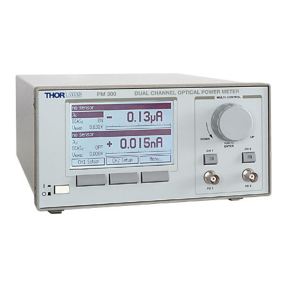
2.3 Physical Overview Via the banana connector jack of the chassis ground the external optical build-up can be connected to ground potential, if required. 2.3 Physical Overview 2.3.1 Operating Elements at the Front Panel Control Knob Power Switch Soft Keys Display Selector Photodiode Inputs CH1;... -
Page 14: Operating Elements At The Rear Panel
2.3 Physical Overview 2.3.2 Operating Elements at the Rear Panel Ground Connector (4mm banana) USB Interface Misc. Out: Analog Outputs Mains Connector Connector Programmable CH1, CH2 Including line switch (Type ‘B’) Analog Output (BNC) and fuses (BNC) CH2 PD Sensor CH1 PD &... -
Page 15: Main Screens
2.3 Physical Overview 2.3.3 Main Screens Channel Header with Display, Channel and Sensor Information Main Display CH1 Main Display CH2 Soft Keys Figure 3 Dual Channel Screen Directly Main Display accessible Menus Sub Display Bargraph (Main Display) Figure 4 Single Channel Screen (CH1) Figure 5 Trend Graph Channel 1... -
Page 16: Operating The Pm300
3.1 Sensor independent Operation and Settings 3.1.1 Navigating the Menus The PM300 is controlled by three display/menu dependent soft buttons below the graphics display and/or the control knob including a push button with an Edit/Enter functionality. All displays have directly accessible menus by navigating and clicking with the Multi-Control knob. -
Page 17: Readout Configuration
Voltage [V] 3.1.4 Range Setting The PM300 provides sensor dependent up to seven power corresponding current and up to four power corresponding voltage measurement ranges that can be selected in manual- and auto-range mode. To select a range or switch to the auto- range mode navigate to the ‘Range’... -
Page 18: Relative Power Measurement
3.1 Sensor independent Operation and Settings selected range immediately gets active after selecting. To leave the menu press the control knob or the <ok> soft key. When power-meter sensors are connected the ranges will show in Watts; for the photodiode inputs in Ampere, for the thermal head adapter in Volts. Figure 6 Range Setting with a photodiode sensor 3.1.5 Relative Power Measurement... -
Page 19: Setting An Attenuation Factor
Attenuation 3.2 Operation with a Photodiode Sensor Photodiode sensors of the Thorlabs S1xx series can be connected to each of the Sub-D jacks in the rear panel. The sensor will be recognized immediately after plugging. When a power meter sensor is plugged the related photo-diode input in the front panel gets inactive. -
Page 20: Wavelength Correction
5nm steps. Each sensors spectral responsivity data gets stored in a non-volatile memory inside the DB-9 sensor connector and downloaded to the PM300 when plugged to the unit. To perform an accurate measurement it is necessary to enter the operating wavelength that the PM300 can calculate the laser power from the measured photo current and the right responsivity value from the wavelength calibration table. -
Page 21: Dark Current Adjustment
(laser switched off) and press the Control knob or press the <Enter> soft button. The PM300 will automatically switch down to the smallest possible measurement range, measure the photo current and from now on take in account this value when calculating the power reading. -
Page 22: Bandwidth Setting
3.2 Operation with a Photodiode Sensor 3.2.3 Bandwidth Setting The analog bandwidth can be set in the channel setup to ‘high’ (range dependent bandwidth) and ‘low’ (15 Hz bandwidth). The bandwidth setting mainly influences the analog outputs to for example subtract noise from the mains. The digital power readings and the bar graph have a digital filtering (including a selectable 50/60Hz line filter) that’s combined bandwidth approximately corresponds to the ‘low’-bandwidth setting. -
Page 23: Operation With A Thermal Sensor
3.3 Operation with a Thermal Sensor 3.3 Operation with a Thermal Sensor Thermal sensors of the Thorlabs S2xx series can be connected (only) to the CH1 Sub-D jack in the rear panel. The sensor will be recognized immediately after plugging. When a power meter sensor is plugged the related photo-diode input in the front panel gets inactive. -
Page 24: Readout Acceleration
2 and 6 with a wire connection see sensor pin-out chapter 7.4 The PM300 will recognize a ‘Thermal Head Adapter’ with the possibility to read the measurement value in Volts or by entering a responsivity factor in V/W also as power value in Watts or dBm. -
Page 25: Photodiode Polarity
3.5 Analog Outputs 3.4.1 Photodiode Polarity The photodiode polarity must be set that the measured current shows a positive reading, otherwise the display will show ‘------‘ when switching to a power display in mW or dBm. To set the polarity enter the <CHx Setup> and navigate to the ‘PD Pol’ menu. -
Page 26: Miscellaneous Analog Output
3.6 Miscellaneous Analog Output selected bandwidth. With thermal sensors the analog output shows the direct response from the thermal sensor without the accelerator circuit. This signal is not wavelength corrected. The voltage is range dependent and can go from -10V to +10V. -
Page 27: System Configuration
4 Computer Interface The PM300 optical power meter has a USB 2.0 interface that allows to send commands from a host computer to the instrument. The connection between PC and PM 300 is accomplished by a USB cable with a male type ‘A’ connector at the PC side and a type ‘B’... -
Page 28: Pm300 Utility Software
Administrator privileges on the PC which you are perform- ing the install. Prior to connecting the PM300 with the PC, please insert the CD that shipped with the instrument and install the PM300 drivers. When the following message appears... -
Page 29: Firmware Update
4.3 Firmware Update The utility software will recognize and update connected sensors while the program is running. The display data can be logged to a file after pressing the <START> and <Log To File> buttons. 4.3 Firmware Update Firmware upgrades can be done by the user via the USB interface. Therefore install the DFU (device firmware upgrade) wizard from the distribution CD. -
Page 30: Command Reference
4.4 Command Reference Connect the PM300 to a USB port of your PC and launch the DFU wizard from the start bar. Follow the wizard instructions. Please refer to www.thorlabs.com for the latest PM300 firmware version. When proceeding the DFU wizard the first time a new DFU device will be recognized, please allow installing. - Page 31 4.4 Command Reference *IDN? Identification query. (IEEE488.2-1992-§10.14) *TST? Selftest query. (IEEE488.2-1992-§10.38) *OPC Operation complete command. (IEEE488.2-1992-§10.18) Operation complete query. (IEEE488.2-1992-§10.19) *OPC? Wait command. (IEEE488.2-1992-§10.39) *WAI Reset command. (IEEE488.2-1992-§10.32) *RST *SRE Service Request Enable command. (IEEE488.2-1992-§10.34) *SRE? Service Request Enable query. (IEEE488.2-1992-§10.35) *STB? Read Status Byte query.
- Page 32 4.4 Command Reference 4.4.1.2.3 Operation Complete Command Command *OPC syntax: Sets the ‘OPC’ bit in the ‘Standard Event Status Register’ (see also Description: IEEE488.2-1992-§10.18). 4.4.1.2.4 Operation Complete Query Command *OPC? syntax: Response <NR1 NUMERIC RESPONSE DATA> syntax: The Operation Complete Query places a ‘1’ into the device’s output Description: queue (see also IEEE488.2-1992-§10.19).
- Page 33 4.4 Command Reference syntax: Response <NR1 NUMERIC RESPONSE DATA> syntax: Description: Queries the device’s Service Request Enable Register (see also IEEE488.2-1992-§10.35 chapter ‘Status Reporting’ in this document). 4.4.1.2.9 Read Status Byte Query Command *STB? syntax: Response <NR1 NUMERIC RESPONSE DATA> syntax: Description: Queries the device’s Status Byte (see also IEEE488.2-1992-§10.36 and...
-
Page 34: Measurement Commands
4.4 Command Reference IEEE488.2-1992-§10.12 chapter ‘Status Reporting’ in this document). 4.4.1.2.13 Clear Status Commend Command *CLS syntax: Prerequisite: None Description: Clears the following device’s status registers (see also IEEE488.2-1992- §10.3): • Standard Event Status Register • Device Error Event Register •... - Page 35 4.4 Command Reference syntax: Description: Queries the currently used averaging rate for channel 1/2. 4.4.2.2.2 Set the Averaging Rate Command :AVER[1,2] <DECIMAL NUMERIC PROGRAM DATA> syntax: Description: Sets the averaging rate for channel 1/2. Note: The averaging rate does not influence the front panel display. The instrument measures at 500Hz rate.
-
Page 36: Device Setup Commands
4.4 Command Reference 4.4.2.2.6 Query the Zero Offset Value Command :ZERO[1,2]:VAL? syntax: Zero offset value <NR3 NUMERIC RESPONSE DATA> Response syntax: Description: Queries the currently used channel 1/2 zero offset value in Ampere/Volt. 4.4.2.2.7 Perform a Zero Offset Value Adjustment Command :ZERO[1,2]:ADJ syntax:... - Page 37 4.4 Command Reference :URANGE1:MIN? Query the channel 1 minimum settable voltagerange. :URANGE1:MAX? Query the channel 1 maximum settable voltage range. :WAVEL[1,2]:VAL Set the wavelength for channel 1/2 Query the currently used wavelength for channel 1/2 :WAVEL[1,2]:VAL? Query the channel 1/2 wavelength range :WAVEL[1,2]:RNG? Set the channel 1/2 power attenuation :ATTEN[1,2]:VAL...
- Page 38 4.4 Command Reference 4.4.3.2 Description 4.4.3.2.1 Set Channel 1/2 Power Range Com- :PRANGE[1,2] <CHARACTER PROGRAM DATA> mand [AUTO,R1NW,R10NW,R100NW,R1UW,R10UW,R100UW,R1MW,R10MW,R100MW, syntax: R1W,R10W,R100W,R1KW] Descrip- Sets the power range for channel 1/2. tion: 4.4.3.2.2 Query Channel 1/2 Power Range Com- :PRANGE[1,2]? mand syntax: <CHARACTER RESPONSE DATA>...
- Page 39 4.4 Command Reference R1W,R10W,R100W,R1KW] Description: Queries the channel 1/2 maximum settable power range.
- Page 40 4.4 Command Reference 4.4.3.2.5 Set Channel 1/2 Current Range Command :IRANGE[1,2] <CHARACTER PROGRAM DATA> syntax: [AUTO,R10NA,R100NA,R1UA,R10UA,R100UA,R1MA,R10MA] Description: Sets the current range for channel 1/2. 4.4.3.2.6 Query Channel 1/2 Current Range Command :IRANGE[1,2]? syntax: Response <CHARACTER RESPONSE DATA> syntax: [AUTO,R10NA,R100NA,R1UA,R10UA,R100UA,R1MA,R10MA] Description: Queries the channel 1/2 current range.
- Page 41 4.4 Command Reference 4.4.3.2.11 Query Channel 1 Minimum Voltage Range Command :URANGE1:MIN? syntax: Response <CHARACTER RESPONSE DATA> syntax: [AUTO,R100UV,R1MV,R10MV,R100MV] Description: Queries the channel 1 minimum settable voltage range. 4.4.3.2.12 Query Channel 1 Maximum Voltage Range Command :URANGE1:MAX? syntax: Response <CHARACTER RESPONSE DATA> syntax: [AUTO,R100UV,R1MV,R10MV,R100MV] Description:...
- Page 42 4.4 Command Reference 4.4.3.2.16 Set Channel 1/2 Power Attenuation Command :ATTEN[1,2]:VAL <DECIMAL NUMERIC PROGRAM DATA> syntax: Description: Sets the channel 1/2 power attenuation [dB]. 4.4.3.2.17 Query Channel 1/2 Power Attenuation Command :ATTEN[1,2]:VAL? syntax: currently used power attenuation <NR3 NUMERIC RESPONSE DATA> Response syntax: Description:...
- Page 43 4.4 Command Reference 4.4.3.2.21 Set Channel 1/2 Photodiode Input Polarity Command :PDPOL[1,2] <CHARACTER PROGRAM DATA> [AG,CG] syntax: Description: Sets the photodiode input polarity to anode ground/cathode ground.. 4.4.3.2.22 Query Channel 1/2 Photodiode Input Polarity Command :PDPOL[1,2]? syntax: Response <CHARACTER RESPONSE DATA> [AG,CG] syntax: Description: Queries the photodiode input polarity.
- Page 44 4.4 Command Reference 4.4.3.2.26 Set Channel 1/2 Photodiode Input BIAS State Command :PDBIAS[1,2] <CHARACTER PROGRAM DATA> [ON,OFF] syntax: Description: Switches the photodiode input BIAS voltage on/off.. 4.4.3.2.27 Query Channel 1/2 Photodiode Input BIAS State Command :PDBIAS[1,2]? syntax: Response <CHARACTER RESPONSE DATA> [ON,OFF] syntax: Description: Queries the photodiode input BIAS state.
- Page 45 4.4 Command Reference 4.4.3.2.31 Set Channel 1 Thermopile Sensor Accelerator State Command :THACCEL1 <CHARACTER PROGRAM DATA> [OFF,ON] syntax: Description: Sets the thermopile sensor accelerator state. 4.4.3.2.32 Query Channel 1 Thermopile Sensor Accelerator State Command :THACCEL1? syntax: Response <CHARACTER RESPONSE DATA> [OFF,ON] syntax: Description: Queries the thermopile sensor accelerator state.
-
Page 46: Sensor Commands
4.4 Command Reference 4.4.4 Sensor Commands 4.4.4.1 Command List Command Description :SENS[1,2]:TYPE? Query the channel 1/2 optical sensor’s type. :SENS[1,2]:NAME? Query the channel 1/2 optical sensor’s name. :SENS[1,2]:SERNR? Query the channel 1/2 optical sensor’s serial number. :SENS[1,2]:RANGE? Query the channel 1/2 optical sensor’s range data. 4.4.4.2 Description 4.4.4.2.1 Query Channel 1/2 Optical Sensor Type/ID Command... - Page 47 4.4 Command Reference 4.4.4.2.2 Query Channel 1/2 Optical Sensor Name Command :SENS[1,2]:NAME? syntax: Response <ARBITRARY ASCII RESPONSE DATA> syntax: Description: Queries the name of the connected optical sensor. 4.4.4.2.3 Query Channel 1/2 Optical Sensor Serial Number Command :SENS[1,2]:SERNR? syntax: Response <ARBITRARY ASCII RESPONSE DATA>...
-
Page 48: Misc-Output Commands
4.4 Command Reference 4.4.5 MISC-Output Commands 4.4.5.1 Command List Command Description :MISCOUT:MODE Set the MISC-Output operating mode :MISCOUT:MODE? Query the MISC-Output operating mode :MISCOUT:SENS:WATT Set the MISC-Output sensitivity for Watt modes :MISCOUT:SENS:WATT? Query the MISC-Output sensitivity for Watt modes :MISCOUT:SENS:DBM Set the MISC-Output sensitivity for dBm modes :MISCOUT:SENS:DBM? Query the MISC-Output sensitivity for dBm modes... - Page 49 4.4 Command Reference 4.4.5.2.2 Query MISC-Output Operating Mode Com- :MISCOUT:MODE? mand syntax: Response <CHARACTER RESPONSE DATA> syntax: [POW1W,POW1DBM,SUB12,RATIO12,POW2W,POW2DBM,SUB21,RATIO21 ,OFFSET] Descrip- Queries the MISC-Output operating mode. tion: 4.4.5.2.3 Set MISC-Output sensitivity (Watt modes) Com- :MISCOUT:SENS:WATT <CHARACTER PROGRAM DATA> mand [R1NW,R3NW,R10NW,R30NW,R100NW,R1UW,R3UW,R10UW,R30UW,R100UW, syntax: R1MW,R3MW,R10MW,R30MW,R100MW,R1W,R3W,R10W,R30W,R100W] Descrip- Sets the MISC-Output sensitivity for Watt modes according to the following...
- Page 50 4.4 Command Reference R30W 1V / 30W R100W 1V / 100W 4.4.5.2.4 Query MISC-Output sensitivity (Watt modes) Com- :MISCOUT:SENS:WATT? mand syntax: <CHARACTER RESPONSE DATA> sponse [R1NW,R3NW,R10NW,R30NW,R100NW,R1UW,R3UW,R10UW,R30UW,R100UW, syntax: R1MW,R3MW,R10MW,R30MW,R100MW,R1W,R3W,R10W,R30W,R100W] Descrip- Queries the MISC-Output sensitivity for Watt modes. tion: 4.4.5.2.5 Set MISC-Output sensitivity (dBm modes) Command :MISCOUT:SENS:DBM <CHARACTER PROGRAM DATA>...
- Page 51 4.4 Command Reference R0_3DB 1V / 0.3dB R1DB 1V / 1dB 1V / 3dB R3DB R10DB 1V / 10dB 4.4.5.2.8 Query MISC-Output sensitivity (dB modes) Command :MISCOUT:SENS:WATT? syntax: Response <CHARACTER RESPONSE DATA> syntax: [R0_1DB,R0_3DB,R1DB,R3DB,R10DB] Description: Queries the MISC-Output sensitivity for dB modes. 4.4.5.2.9 Set MISC-Output Offset Voltage Command :MISCOUT:OFFS:VAL <DECIMAL NUMERIC PROGRAM DATA>...
-
Page 52: Device Status Commands
4.4 Command Reference 4.4.6 Device Status Commands 4.4.6.1 Command List Command Description :STAT:ERR:CND? Query the Device Error Condition register. :STAT:ERR:EVT? Query the Device Error Event register. :STAT:ERR:ENA? Query the Device Error Event Enable register. :STAT:ERR:ENA Set the Device Error Event Enable register. :STAT:OPER:CND? Query the Device Operation Condition register. - Page 53 4.4 Command Reference syntax: Description: Sets the device’s Error Event Enable Register (see also chapter chapter ‘Status Reporting’ in this document). 4.4.6.2.4 Query Device Error Event Enable Register Command :STAT:ERR:ENA? syntax: Response <NR1 NUMERIC RESPONSE DATA> syntax: Description: Queries the device’s Error Event Enable Register (see also chapter ‘Status Reporting’...
-
Page 54: General System Commands
4.4 Command Reference Response <NR1 NUMERIC RESPONSE DATA> syntax: Description: Queries the device’s Operation Event Enable Register (see also chapter ‘Status Reporting’ in this document). 4.4.7 General System Commands 4.4.7.1 Command List Command Description :SYST:ERR? Query the device’s error queue. :SYST:OPTIONS? Query the hardware and software options. - Page 55 4.4 Command Reference Hardware Options <HEXADECIMAL NUMERIC RESPONSE DATA>, Response Software Options <HEXADECIMAL NUMERIC RESPONSE DATA>, syntax: Mainboard ID <NR1 NUMERIC RESPONSE DATA> Description: Queries the device’s hardware option bitmap, software option bitmap and the mainboard ID. For further information see chapters ‘Hardware Options’, ‘Software Options’...
- Page 56 4.4 Command Reference Response <ARBITRARY ASCII RESPONSE DATA> syntax: Description: Queries descriptive device information. 4.4.7.2.7 Set Linefilter Command :SYST:LINEFILTER <CHARACTER PROGRAM DATA> [50HZ,60HZ] syntax: Description: Sets the device line filter setting. Note: For optimum device operation set the line filter to your local mains frequency.
-
Page 57: Measurement Considerations
5 Measurement Considerations 5.1 Measurement of Pulsed Signals The PM300 will read the average value of a pulsed signal when the following conditions apply. For a thermal sensor pulse length, repetition rate and peak power is uncritical as long as the peak power is lower than the damage threshold of the sensor. -
Page 58: Ambient And Stray Light
This expansion of the beam has to be considered to avoid overfilling the detector and getting wrong results. Thorlabs offers fiber adapters with the most common connectors that are verified with the S12xB series optical sensors. For very large divergence angles it is recom-... -
Page 59: Maintenance And Repair
If necessary the unit and the display can be cleaned with a cloth dampened with water. The PM300 does not contain any modules that could be repaired by the user himself. If a malfunction occurs, the whole unit has to be sent back to Thorlabs. Do not remove covers! To guarantee the specifications given in chapter 7.3 over a long period it is... -
Page 60: Line Voltage Setting
6.2 Line voltage setting 6.2 Line voltage setting The PM300 optical power meter operates at fixed line voltages of 100 V +10% -10% (90 V … 115 V), 115 V +10% -10% (104 V … 132 V) or 230 V +10% -10% (207 V … 264 V). -
Page 61: Replacing The Mains Fuses
To avoid risk of fire the appropriate fuses for the corresponding line voltage must be used. 1. Turn off the PM300 and disconnect the mains cable. 2. The fuse holder (see Figure 15) is located below the 3-pole power connector of the mains jack. - Page 62 6.3 Replacing the mains fuses Mains jack Voltage switch / Fuses indicator Fuse holder Window for line voltage setting Figure 15 Setting the line voltage or changing the mains fuses...
-
Page 63: Troubleshooting
6.4 Troubleshooting 6.4 Troubleshooting In case that your PM300 shows malfunction please check the following items: Unit does not work at all (no display at the front): PM300 connected properly to the mains? Check the mains cable and the line voltage setting (please refer to section 6.2 on page 58) - Page 64 6.4 Troubleshooting If you don’t find the error source by means of the trouble shooting list please first contact the Thorlabs-Hotline ( europe@thorlabs.com) before sending the PM300 for checkup and repair to Thorlabs - Germany. (refer to section 7.9, ‘Addresses” on page 82)
- Page 65 6.4 Troubleshooting This page is intentionally left blank...
-
Page 67: Appendix
7.1 Warranty 7 Appendix 7.1 Warranty Thorlabs warrants material and production of the PM300 for a period of 24 months starting with the date of shipment. During this warranty period Thorlabs will see to defaults by repair or by exchange if these are entitled to warranty. -
Page 68: Certifications And Compliances
7.2 Certifications and compliances 7.2 Certifications and compliances Certifications and compliances Category Standards or description EC Declaration Meets intent of Directive 89/336/EEC for Electromagnetic Compatibility. Compliance of Conformity – was demonstrated to the following specifications as listed in the Official Journal of the European Communities: EN 61326:1997 Electrical equipment for measurement, control and... -
Page 69: Technical Data
7.3 Technical data 7.3 Technical data 7.3.1 Common Data Line voltage (selectable) 100 V / 115 V / 230 V (-10%, +10 %) Line frequency 50 ... 60 Hz Power consumption (max.): 20VA Supply mains over voltage Category II (Cat II) 0 ... - Page 70 7.3 Technical data Voltage Input Full scale current measurement ranges 100µV … 100mV (in decade steps) Maximum display resolution 0.1µV Display units V, W, dBm Thermopile sensitivity Input impedance 1MΩ Voltage Range Resolution Gain Accuracy Bandwidth 100 mV 10 µV 1 x 10 +/- 0.5% f.s.
-
Page 71: Pin Assignment Of The Sensor Connector
DGND digital ground The following described pins are uniquely used for the memory in the sensor head and may not be used. Connecting these pins may cause malfunction of the PM300. EEPROM VDD (3.3V) EEPROM SCK EEPROM CS... -
Page 72: Thorlabs Power Sensors
7.5 Thorlabs Power Sensors 7.5 Thorlabs Power Sensors 7.5.1 S120B / S121B Silicon Sensor Figure 17 S120B / S121B Mechanical Drawing Specifications: Spectral range: 400 – 1100nm Sensor: Silicon Sensor size: 10mm x 10mm sq. (0.39” x 0.39”) ∅ 9.5mm (0.374”) -
Page 73: S122B Germanium Sensor (Pm122)
7.5 Thorlabs Power Sensors 7.5.2 S122B Germanium Sensor (PM122) Figure 18 S122B Mechanical Drawing Specifications: Spectral range: 700 – 1800nm Sensor: Germanium Sensor size: 10mm x 10mm sq. (0.39” x 0.39”) ∅ 9.5mm (0.374”) Input aperture: Distance to ND filter: 2.6mm (0.10”) -
Page 74: S130A / S132B Slim Sensor (Pm130 / Pm132)
7.5 Thorlabs Power Sensors 7.5.3 S130A / S132B Slim Sensor (PM130 / PM132) Figure 19 S130A / S132A Mechanical Drawing Specifications: S130A S132A Spectral range: 400 – 1100nm 700 – 1800nm Sensor: Silicon Germanium Sensor size: 10mm x 10mm sq. (0.39” x 0.39”) ∅... -
Page 75: S140A / S144A Integrating Sphere Sensor (Pm140 / Pm144)
7.5 Thorlabs Power Sensors 7.5.4 S140A / S144A Integrating Sphere Sensor (PM140 / PM144) Figure 20 S140A / S144A Mechanical Drawing Specifications: S140A S144A Spectral range: 400 – 1100nm 800 – 1700nm Sensor: Silicon InGaAs Measurement Principle: Integrating Sphere ∅ 1mm Sensor size: ∅... -
Page 76: S210A 3W Thermal Sensor
7.5 Thorlabs Power Sensors 7.5.5 S210A 3W Thermal Sensor Figure 21 S210A Mechanical Drawing Specifications: Spectral range: 250nm – 10.6µm Sensor: Thermal Absorber ∅ 19mm (3/4”) Input aperture: Distance to detector: 8.0mm (0.315”) Aperture thread: 3/4”-32 Optical power range: 20mW – 3W... -
Page 77: S212A 10W Thermal Sensor
7.5 Thorlabs Power Sensors 7.5.6 S212A 10W Thermal Sensor Figure 22 S212A Mechanical Drawing Specifications: Spectral range: 250nm – 10.6µm Sensor: Thermal ∅ 12.7mm (1/2”) Input aperture: Distance to detector: 55.9mm (2.20”) Aperture thread: none Optical power range: 20mW – 10W... -
Page 78: S213A 30W Thermal Sensor
7.5 Thorlabs Power Sensors 7.5.7 S213A 30W Thermal Sensor Figure 23 S213A Mechanical Drawing Specifications: Spectral range: 250nm – 10.6µm Sensor: Thermal ∅ 15.8mm (5/8”) Input aperture: Distance to detector: 9.7mm (0.38”) Aperture thread: none Optical power range: 100mW – 30W... -
Page 79: Selection Of Thorlabs Photo-Diodes
7.6 Selection of Thorlabs Photo-Diodes 7.6 Selection of Thorlabs Photo-Diodes 7.6.1 SM05PD Series Figure 24 SM05PD1A cathode grounded silicon diode 7.6.2 SM1PD Series Figure 25 SM1PD1A cathode grounded silicon diode... -
Page 80: Is200 Integrating Sphere Series
M4 and 8-32 Threads at South Pole Available Detectors: Si, InGaAs, Ge, GaP mounted in SM05 package 7.6.4 Calibrated Photodiodes Thorlabs offers calibration service on photodiodes, mounted photodiodes and integrating spheres. Please visit our website www.thorlabs.com or contact our sales... -
Page 81: Thorlabs 'End Of Life" Policy (Weee)
7.7.1 Waste treatment on your own responsibility If you do not return an ‘end of life” unit to Thorlabs, you must hand it to a company specialized in waste recovery. Do not dispose of the unit in a litter bin or at a public... -
Page 82: Ecological Background
7.7 Thorlabs ‘End of Life” policy (WEEE) 7.7.2 Ecological background It is well known that WEEE pollutes the environment by releasing toxic products during decomposition. The aim of the European RoHS directive is to reduce the content of toxic substances in electronic products in the future. -
Page 83: List Of Figures
7.8 List of figures 7.8 List of figures Figure 1 Display and Operating Elements at the Front Panel Figure 2 Operating Elements at the Rear Panel Figure 3 Dual Channel Screen Figure 4 Single Channel Screen (CH1) Figure 5 Trend Graph Channel 1 Figure 6 Range Setting with a photodiode sensor Figure 7... -
Page 84: Addresses
7.9 Addresses 7.9 Addresses For technical support or sales inquiries, please visit us at www.thorlabs.com/contact for our most up-to- date contact information. USA, Canada, and South America UK and Ireland Thorlabs, Inc. Thorlabs Ltd. sales@thorlabs.com sales.uk@thorlabs.com techsupport@thorlabs.com techsupport.uk@thorlabs.com Europe Scandinavia...
Need help?
Do you have a question about the PM300 and is the answer not in the manual?
Questions and answers