Table of Contents
Advertisement
Quick Links
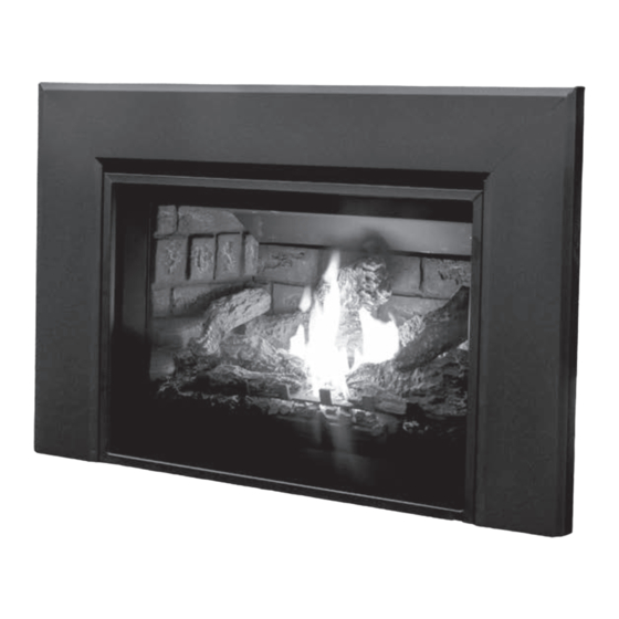
E25 / E25I / E25ID
I P I / N O V A G A S F I R E P L A C E I N S E R T
OWNER'S MANUAL
WARNING:
If the information in this manual is not followed exactly, a
fire or explosion may result causing property damage, personal injury
or loss of life. Installation and service must be performed by a qualified
installer, service agency or the gas supplier.
C#4001609
CERTIFIED TO/ CERTIFIÉ AUX: ANSI Z21.88 / CSA2.33 VENTED GAS FIREPLACE HEATERS
1
C-15958
Version Française: www.enviro.com/fr.html
Advertisement
Table of Contents
Troubleshooting

Related Manuals for Enviro E25ID


Summary of Contents for Enviro E25ID
- Page 1 E25 / E25I / E25ID I P I / N O V A G A S F I R E P L A C E I N S E R T OWNER’S MANUAL WARNING: If the information in this manual is not followed exactly, a fire or explosion may result causing property damage, personal injury or loss of life.
-
Page 2: Safety Precautions
Safety Precautions WARNING: FIRE OR EXPLOSION HAZARD Failure to follow safety warnings exactly could result in serious injury, death, or property damage. - Do not store or use gasoline or other flammable vapors and liquids in the vicinity of this or any other appliance. - WHAT TO DO IF YOU SMELL GAS •... - Page 3 Safety Precautions FOR SAFE INSTALLATION AND OPERATION OF YOUR “ENVIRO” HEATER, PLEASE CAREFULLY READ THE FOLLOWING INFORMATION: • All ENVIRO gas-fired appliances must be installed in • A barrier designed to reduce the risk of burns from the accordance with their instructions. Carefully read all the hot veiwing glass is provided with this appliance and shall instructions in this manual first.
-
Page 4: Table Of Contents
Table of Contents Safety Precautions......................2 Table of Contents......................4 Codes And Approvals.......................5 Specifications........................6 Rating Label Location...................6 Dimensions......................6 Install Depths.......................6 E25 Options Dimensions..................6 Operating Instructions.....................7 Lighting and Turning Off Instructions (IPI).............7 Lighting and Turning Off Instructions (NOVA.)............8 Pilot Light......................8 Burner Lighting - E25 Models.................9 Remote Control Operations...................10 System Description.....................10 Technical Data....................10... -
Page 5: Codes And Approvals
After the unit has gone through the first burn, turn the unit off, let the unit get cold then remove the glass door and clean it with a good gas fireplace glass cleaner, available at your local ENVIRO dealer. See “D ”... -
Page 6: Specifications
Specifications ating abeL ocation The rating label is located in the bottom of the unit. imensions 20.8 10.8 27.3 28.8 13.5 24.4 18.5 19.4 14.1 20.7 nstaLL epth The E25 has a minimum install depth of 13.5” (343mm). 990.60 39.00 1.162 652.78 25.70... -
Page 7: Operating Instructions
For Your Safety, Read Safety Precautions And Lighting Instructions Before Operating WARNING: IF YOU DO NOT FOLLOW THESE INSTRUCTIONS EXACTLY A FIRE OR EXPLOSION MAY RESULT, CAUSING PROPERTY DAMAGE, PERSONAL INJURY OR LOSS OF LIFE. e25i / e25iD L ighting anD uRning... -
Page 8: Lighting And Turning Off Instructions (Nova.)
Operating Instructions For Your Safety, Read Safety Precautions And Lighting Instructions Before Operating WARNING: IF YOU DO NOT FOLLOW THESE INSTRUCTIONS EXACTLY A FIRE OR EXPLOSION MAY RESULT, CAUSING PROPERTY DAMAGE, PERSONAL INJURY OR LOSS OF LIFE. e25 L ighting anD uRning nstRuctions FOR YOUR SAFETY READ BEFORE LIGHTING... -
Page 9: Burner Lighting - E25 Models
After the unit has gone through the first burn, turn the unit OFF, including the pilot, and let the unit get completely cold. Then remove the glass and clean it with a good gas fireplace glass cleaner, available at your local Enviro dealer (See m and m... -
Page 10: Remote Control Operations
Operating Instructions For E25ID models refer to the separate Dexen user manual supplied for remote control operations. emote ontRoL peRations The Proflame 2 GTMFLSA is a modular remote control system that directs the functions of the E25I. The Proflame 2 GTMFLSA is configured to control the on/off main burner operation, its flame levels and provides on/off and Smart thermostatic control of the appliance. -
Page 11: Integrated Fireplace Controller (Ifc)
Operating Instructions e25] ot used oN (ifc): ntegRateD iRepLace ontRoLLeR The Proflame 2 IFC connects directly to the gas valve, stepper motor, pilot, covection fan, and accent lights with wiring harnesses. The IFC is mainly powered by 120 VAC but can also run off a battery backup four (4) AA type batteries for shorter periods of time. -
Page 12: Accessing
Operating Instructions ccessing Due to limited space within the cabinet the IFC & battery pack are located on a sliding tray. Pull the tray forward out of the cabinet to easily access the battery pack and the IFC. The tray has stops to make sure that the cabling is not over stretched. -
Page 13: Operating Procedure
Operating Instructions peRating RoceDuRe Initializing The System For The First Time Install the four (4) AA batteries into the IFC battery holder. Note the polarity of the battery and insert into the battery bay as indicated on the body of the battery holder. Press and release the reset button The IFC will “beep”... - Page 14 Operating Instructions Remote Flame Control The Proflame 2 GTMF has six (6) flame levels. With the system on, and the flame level at the maximum in the appliance, pressing the Down Arrow Key once will reduce the flame height by one step until the flame is turned off. The Up Arrow Key will increase the flame height each time it is pressed.
- Page 15 Operating Instructions Low Battery Power Detection Transmitter: The life span of the remote control batteries depends on various factors: quality of the batteries used, the number of ignitions of the appliance, the number of changes to the room thermostat set point, etc. When the Transmitter batteries are low, a Battery Icon will appear on the LCD display of the Transmitter before all battery power is lost.
-
Page 16: Venturi Adjusment
Operating Instructions entuRi Djustment The venturi adjustment slider is located in the centre of the unit, below the door. The venturi allows the amount of air coming into the fireplace to be adjusted in order to accommodate different climates and venting arrangements. Start the pilot and then the burner. Make sure the pilot flame is burning normally and none of the burner ports are plugged. -
Page 17: Maintenance And Service
Maintenance And Service Warning: Failure to position the parts in accordance with this manual, or failure to use only parts specifically approved with this appliance, may result in property damage or personal injury. At least once a year, run through the following procedures to ensure the system is clean and working properly. -
Page 18: Cleaning The Painted Surfaces
The glass must be purchased from an ENVIRO dealer. No substitute materials are allowed. Remove the door (see page 17). The replacement glass will come with a new gasket installed. Remove any silicone remnants from the door. -
Page 19: Burner Removal
Maintenance And Service uRneR emoVaL The burner may need to be removed for a few reasons, including cleaning under the burner, converting the unit to a different gas type, or to replace the burner altogether. Proceed only when the unit has completely cooled down. Open door and remove Remove log stands and log grate. -
Page 20: Fuel Conversion
E25i & E25 Gas fuel Conversion Instructions Warning: This conversion kit shall be installed by a qualified service agency in accordance with the manufacturer’s instructions and all applicable codes and requirements of the authority having jurisdiction. If the information in these instructions is not followed exactly, a fire, explosion or production of carbon monoxide may result causing property damage, personal injury or loss of life. - Page 21 NOVA SPECIFIC INSTRUCTIONS To gain access to the valve you will need to remove The valve is located in the rear left corner of the front control panel. Remove the the unit. You will need to remove the rod and cap Qty-3 T20 screws holding the control panel on.
- Page 22 IPI SPECIFIC INSTRUCTIONS Pilot Adjustment Inlet Screw Pressure Tap Stepper Regulator Manifold Pressure Tap 7. Convert the SIT gas valve: Disconnect the wire harness from the IFC. Use a T-20 driver to remove the two screws that hold the servo regulator to the gas valve.
-
Page 23: Initial Installation
Initial Installation Safety Screen & Surround Assembly WARNING - Failure to position The surround needs to be assembled be on site. the parts in accordance with these you will need a 7/16” socket or wrench. diagrams or failure to use only parts specifically approved with this Lay down protective material where you intend to assemble appliance may result in property... -
Page 24: Clearances To Combustibles
The E25 / E25I / E25ID may be installed and vented into any solid fuel fireplace that has been installed in accordance with the National, Provincial/State and local building codes and has been constructed of noncombustible materials. Before starting, refer to please reference the termination clearance information on page 28. -
Page 25: Venting
Initial Installation QUALIFIED INSTALLERS ONLY IMPORTANT - Contact your local dealer for further information prior to construction and installation. Non-Combustible Facing Material Only Non-Combustible Framing i.e. steel stud All Sides of Build Out Sealed off Surround Panel Finished Opening Dimensions (H x W) = Surround Panel - Desired Overlap enting WARNING: This appliance has been designed to draw room air for proper heat circulation... - Page 26 Initial Installation QUALIFIED INSTALLERS ONLY The height for the vent must be between 10 ft (3.05 m) and 40 ft (12.19 m). Measured from the fireplace vent collars. Install a sealed vent cap to prevent leakage of room air up through chimney.
-
Page 27: Exhaust Restrictor
Initial Installation QUALIFIED INSTALLERS ONLY xhaust estRictoR This fireplace has an internal exhaust restrictor rings. Usage of the restrictor rings is dependant on the length of venting required and different installation requirements. Use the restrictor rings at your discretion. Be sure a clean healthy burn is 2.5”... - Page 28 Initial Installation QUALIFIED INSTALLERS ONLY Minimum Clearance* Description Clearance above the highest point where it passes through a roof surface, refer to 3 ft (0.9 m) Roof Clearance figure on previous page. Clearance above a roof ridge, any other portion of a building, or any other obstruc- 24 in (0.6 m) tion within a horizontal distance of 10 feet (3 m), refer to Roof Clearance figure on previous page.
- Page 29 Initial Installation QUALIFIED INSTALLERS ONLY 10. If the fireplace opening is lower than 24” (610 mm), remove the vent collar plate from the top of the insert by unlatching the hook located on the center top of the stove above the door opening (see first figure below).
-
Page 30: Horizontal Termination Kits
Initial Installation QUALIFIED INSTALLERS ONLY Horizontal Termination kits The E25 is certified for use with: Duravant - 46DBA-HCL33 ICC - TM-ALH (50-3664) The minimum height that either horizontal kit can be installed at is 6ft. Horizontal termination Vent Height is Measured from the top of the fireplace cabinet. - Page 31 Initial Installation QUALIFIED INSTALLERS ONLY Horizontal Termination Clearances Fixed Closed Fixed Openable Closed Openable Termination Cap Air Supply Inlet Restriction Zone Gas Meter (Termination not allowed) Letter Canadian Installation US Installation Description Clearance above grade, verandah, porch, deck, or balcony. 12 in (30 cm) 9 in (23 cm) Clearance from window or door that may be opened.
-
Page 32: Zero Clearance Fireplace Installation
Initial Installation QUALIFIED INSTALLERS ONLY (zc) f LeaRance iRepLace nstaLLation The metal floor of the ZC solid fuel firebox can be removed to allow the installation of the insert. THE CLEARANCE TO COMBUSTIBLE MATERIAL UNDER THE INSERT IS 0” (0 mm). YOU DO NOT NEED TO RAISE THE UNIT OFF OF A COMBUSTIBLE FLOOR. -
Page 33: Wiring Diagram - E25I Models
Initial Installation QUALIFIED INSTALLERS ONLY Wiring Diagram - E25I Models Note: For E30ID specific wiring diagram refer to the Dexen user manual supplied Proflame 2 System - Wiring Diagram and label attached to the fireplace. Transmitter - TMFLSA IPI Pilot 885 Gas Valve Battery Holder... -
Page 34: Gas Line Connection
Fully Labeled Gas Valve - E25I . Fully Labeled Gas Valve - E25 . See Dexen User Manual for E25ID valve details The appliance must be disconnected from the gas supply piping system during any pressure testing where the pressure exceeds ½ PSIG (3.45 KPa) or damage will occur to the valve. The appliance must be isolated from the gas supply piping system by closing its individual manual shutoff valve during any pressure testing of the gas supply piping system at test pressures equal to or less than ½... -
Page 35: Adjusting The Pilot Flame
” (8 mm) I.D. hose over pressure tap system. • Check pressures using a manometer. • When finished, release pressure, remove hose & tighten set screw. Orifice and Pressure Information. E25 / E25I / E25ID with Log Set Main Burner Natural Gas Propane Gas... -
Page 36: Secondary Installation
Secondary Installation Log Setup Guide Place back log at back of Rotate the log grate (A) into firebox, over top of pilot hood. slots on log deflector (B). Locate notches on log stand (A) Locate notches on log stand (A) into holes on log deflector. - Page 37 Place log on log stand. The back left corner of Place log on log stand. The back right corner of the log locates into the corner of the log stand the log locates into the corner of the log stand Insert the (A) log onto the back pin aligning the Using the brush supplied, lightly brush the ember wool front of the log to the flat part of the front log.
- Page 38 A small amount on the bottom side of the logs is normal. Remove and replace the logs in the same manner described above. If new logs are required, contact your nearest ENVIRO dealer. Never operate the fireplace with the glass door removed.
-
Page 39: Troubleshooting - E25I
TroubleShooting - E25I e25iD iagnostic Lash oDes Does not appLy to moDeLs 1. Fail to ignite: If there is no positive ignition, the board will go into lock out and the LED will blink 3 times in intervals until the system is reset. - Page 40 TroubleShooting - E25I Note: For E25ID specific troubleshooting refer to the Dexen user manual supplied Problem Possible Cause Solution The pilot flame has gone out Thermostat · Turn it ON does not The On/Off switch is turn to OFF work The thermostat is set too high ·...
- Page 41 TroubleShooting - E25I Problem Possible Cause Solution · Turn the system off by pressing the ON/OFF button on the transmitter · After approximately 2 seconds press the ON/OFF button on the transmitter again. · In the manual flame control mode, use the down arrow button to reduce the flame to off, indicated by the word OFF displayed on the transmitter LCD screen.
-
Page 42: Troubleshooting - E25
TroubleShooting - E25 Problem Possible Cause Solution The main burner does not The gas valve may not be on. • Check that the gas control knob is in the “ON” position. ignite when called for. Thermostat is not calling for •... -
Page 43: Parts Diagram - Components
Parts Diagram - Components... -
Page 44: Parts List
Parts List Reference Part Description Part Number Number E25 Log Grate 50-3989 Door Release Tool 50-2510 Flue Adapter Tool 50-3505 E25 Exhaust Restrictors 50-3990 Proflame 2 Transmitter 50-3265 Fan Controller EF-045 FPI Burner Switch EC-026 Battery Holder 4 x AA 50-3027 E25 Power Cord (115V) EC-042... -
Page 45: Warranty
Sherwood Industries Ltd. (“Sherwood”) hereby warrants, subject to the terms and conditions herein set forth, this product against defects in material and workmanship An expanded list of exclusions is available at www.enviro.com/help/warranty.html during the specified warranty period starting from the date of original purchase at retail. -
Page 46: Installation Data Sheet
DIRECT VENT _________________________________________ NATURAL GAS (NAT) PROPANE(LPG) _________________________________________ INLET GAS PRESSURE:_________in WC PHONE:___________________________________ MAIN BURNER ORIFICE:__________# DMS PILOT ORIFICE #_________OR________in diam. INSTALLER’S SIGNATURE: _________________________________________ MANUFACTURED BY: SHERWOOD INDUSTRIES LTD. 6782 OLDFIELD RD. SAANICHTON, BC, CANADA V8M 2A3 www.enviro.com February 2022 C-15958...
Need help?
Do you have a question about the E25ID and is the answer not in the manual?
Questions and answers