Table of Contents
Advertisement
Quick Links
Advertisement
Table of Contents

Related Manuals for ADLINK Technology PCI-8132


Summary of Contents for ADLINK Technology PCI-8132
- Page 1 PCI-8132 2 Axes Servo / Stepper Motion Control Card User’s Guide...
- Page 3 Trademarks NuDAQ, PCI-8132 are registered trademarks of ADLink Technology Inc, MS-DOS , Windows 95/98 , Windows NT/2000 are registered trademarks of Microsoft Corporation., Borland C++ is a registered trademark of Borland International, Inc.
- Page 4 Getting service from ADLINK Customer Satisfaction is always the most important thing for ADLink Tech Inc. If you need any help or service, please contact us and get it. ADLINKTechnology Inc. Web Site http://www.adlink.com.tw http://www.adlinktechnology.com Sales & Service service@adlink.com.tw Technical NuDAQ nudaq@adlink.com.tw Support...
-
Page 5: Table Of Contents
Table of Contents Chapter 1 Introduction ..............1 Features................4 Specifications ..............5 Software Supporting............6 Chapter 2 Installation..............7 What You Have..............7 PCI-8132 Outline Drawing..........8 Hardware Installation............9 2.3.1 Hardware configuration..............9 2.3.2 PCI slot selection ................9 2.3.3 Installation Procedures ..............9 2.3.4 Trouble shooting:................9 Software Driver Installation..........10 CN1 Pin Assignments: External Power Input.... - Page 6 ORG....................50 4.3.4 SVON and RDY................50 The Encoder Feedback Signals (EA, EB, EZ) ....50 Multiple PCI-8132 Cards Operation ......... 52 Change Speed on the Fly..........53 Position Comparison ............55 Interrupt Control ............. 59 Chapter 5 Motion Creator............63 Main Menu ..............
- Page 7 Chapter 6 Function Library ............76 List of Functions............. 76 C/C++ Programming Library ........... 80 Initialization ..............81 Pulse Input / Output Configuration ......... 83 Continuously Motion Move ..........84 Trapezoidal Motion Mode..........85 S-Curve Profile Motion............ 88 Multiple Axes Point to Point Motion ........ 90 Linear and Circular Interpolated Motion ......
-
Page 8: How To Use This Guide
How to Use This Guide This manual is designed to help you use the PCI-8132. The manual describes how to modify various settings on the PCI-8132 card to meet your requirements. It is divided into seven chapters: Ÿ Chapter 1, "Introduction", gives an overview of the product features, applications, and specifications. -
Page 9: Chapter 1 Introduction
Introduction The PCI-8132 is a 2 axes motion control card with PCI interface. It can generate high frequency pulses to drive stepping motors and servo motors. Multiple PCI-8132 cards can be used in one system. Incremental encoder interface on all four axes provide the ability to correct for positioning errors... - Page 10 DC/DC Ext +5V out Mechanic Servo General Pulser Compariso Pulse I/O Driver Purpose Interface Interface Output OUT, +EL, -EL, INP, ALM SVON/RDY DIR, PA/PB CMP1 +SD,-SD, DI/DO 0~15 EA, EB, CMP2 Figure 1.1 Block Diagram of PCI-8132 2 • Introduction...
- Page 11 Hardware Installation Jumper Setting Chapter 2 & 3 Wiring Run Motion Creator Chapter 5 To Configure System Run Motion Creator Chapter 4 & 5 To Verify Operation Use Function Library Chapter 4 & 6 To develop Applications System is Figure 1.2 Flowchart of building an application Introduction •...
-
Page 12: Features
Features The following lists summarize the main features of the PCI-8132 motion control system. Ÿ 32-bit PCI-Bus, plug and play. Ÿ 2 axes of step and direction pulse output for controlling stepping or servomotor. Ÿ Maximum output frequency of 2.4 Mpps. -
Page 13: Specifications
Specifications ♦ Applicable Motors: Ÿ Stepping motors. Ÿ AC or DC servomotors with pulse train input servodrivers. ♦ Performance: Ÿ Number of controllable axes: 2 axes. Ÿ Maximum pulse output frequency: 2.4Mpps, linear, trapezoidal or S-Curve velocity profile drive. Ÿ Internal reference clock: 9.8304 MHz Ÿ... -
Page 14: Software Supporting
Ÿ Dimension: 164mm(L) X 98.4mm(H) Software Supporting For the customers who are writing their own programs, we provide MS-DOS Borland C/C++ programming library and Windows -95/98/NT DLL for PCI-8132. These function libraries are shipped with the board. 6 • Introduction... -
Page 15: Chapter 2 Installation
Installation This chapter describes how to install the PCI-8132. Please follow the follow steps to install the PCI-8132. Ÿ Check what you have (section 2.1) Ÿ Check the PCB (section 2.2) Ÿ Install the hardware (section 2.3) Ÿ Install the software driver (section 2.4) Ÿ... -
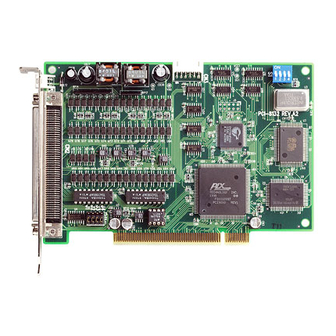
Page 16: Pci-8132 Outline Drawing
PCI-8132 Outline Drawing Front Panel Figure 2.1 PCB Layout of the PCI-8132 CN1: External Power Input Connector CN2: Input / Output Signal Connector CN3: Simultaneous Start/Stop 8 • Installation... -
Page 17: Hardware Installation
2.3.2 PCI slot selection Your computer will probably have both PCI and ISA slots. Do not force the PCI card into a PC/AT slot. The PCI-8132 can be used in any PCI slot. 2.3.3 Installation Procedures Read through this manual, and setup the jumper according to your... -
Page 18: Software Driver Installation
(AWG28 to AWG22) Naked wire length:10mm standard The following diagram shows the exte rnal power supply system of the PCI-8132. The external +24V power must be provided, an on-board regulator generates +5V for both internal and external usage. (External Power) -
Page 19: Cn2 Pin Assignments: Main Connector
CN2 Pin Assignments: Main connector The CN2 is the major connector for the motion control I/O signals. Name Function(axis•/‚) Name Function(axisƒ/„) VPP +5V +5V power supply output DO COM+ Ext power input for Dout EXGND Ext. power ground EXGND Ext. power ground OUT1+ Pulse signal (+),•... -
Page 20: Cn3 Pin Assignments: Simultaneous Start/Stop
CN3 Pin Assignments: Simultaneous Start/Stop The signals on CN3 is for simultaneously start/stop signals for multiple axes and multiple cards. Name Function(Axis ) Bus power ground Simultaneous stop signal input/output Simultaneous start signal input/output Simultaneous stop signal input/output Simultaneous start signal input/output Bus power, +5V Note: +5V and GND pins are directly given by the PCI Bus power. -
Page 21: Jumper Setting
Jumper Setting The J1~J4 is used to set the signal type of the pulse output signals (DIR and OUT). The output signal type could be differential line driver output or open collector output. Please refer to section 3.1 for details of the jumper setting. -
Page 22: Chapter 3 Signal Connections
Signal Connections The signal connections of all the I/O signals are described in this chapter. Please refer the contents of this chapter before wiring the cable between the PCI-8132 and the motor drivers. This chapter contains the following sections: Section 3.1 Pulse output signals OUT and DIR Section 3.2... -
Page 23: Pulse Output Signals Out And Dir
Pulse Output Signals OUT and DIR There are 2-axis pulse output signals on PCI-8132. For every axis, two pairs of OUT and DIR signals are used to send the pulse train and to indicate the direction. The OUT and DIR signals can also be programmed as CW and CCW signals pair, refer to section 4.1.1 for... - Page 24 The following wiring diagram is for the OUT and DIR signals of the 2 axes. Inside PCI-8132 EX+5V J1~J8 OUT+, DIR+ OUT-, DIR- 2631 EXGND from PCL5023 NOTE: If the pulse output is set to the open collector output mode, the OUT- and DIR- are used to send out signals.
-
Page 25: Encoder Feedback Signals Ea, Eb And Ez
EZ2+ • ‚ EZ1- EZ2- The input circuits of the EA, EB, EZ signals are shown as follows. Inside PCI-8132 EA+, EB+, PCL5023 EA, EB EA-, EB- Please note that the voltage across every differential pair of encoder input signals (EA+, EA-), (EB+, EB-) and (EZ+, EZ-) should be at least 3.5V or higher. - Page 26 ♦ Connection to Line Driver Output To drive the PCI-8132 encoder input, the driver output must provide at least 3.5V across the differential pairs with at least 6 mA driving capability. The ground level of the two sides must be tight together too.
-
Page 27: Origin Signal Org
The specifications of the limit switches should with contact capacity of +24V, 6mA minimum. An internal filter circuit is used to filter out the high frequency spike, which may cause wrong operation. Inside PCI-8132 EX+24V 4.7K Filter... -
Page 28: End-Limit Signals Pel And Mel
‘B -type’ (normal closed) contact switch by setting the DIP switch S1. The PCI-8132 is delivered with all bits of S1 set to OFF, refer to section 2.10. For the details of the EL operation, please refer to section 4.3.2. -
Page 29: Ramping-Down Signals Psd And Msd
The signals connection and relative circuit diagram is shown in the following diagram. Usually, limit switches are used to generate the slow-down signals to make motor operating in a slower speed. For more details of the SD operation, please refer to section 4.3.1. Inside PCI-8132 EX+24V 4.7K Filter... -
Page 30: In-Position Signal Inp
Axis # • INP1 ‚ INP2 The input circuit of the INP signals are shown in the following diagram. Inside PCI-8132 EX+5V To PCL5023 =12mA Max. =5mA Min. The in-position signals are usually from servomotor drivers, which usually provide open collector output signals. The external circuit must provide at least 5 mA current sink capability to drive the INP signal active. -
Page 31: Alarm Signal Alm
The external circuit must provide at least 5 mA current sink capability to drive the ALM signal active. For more details of the ALM operation, please refer to section 4.2.2. Inside PCI-8132 EX+5V To PCL5023 =12mA Max. -
Page 32: Deviation Counter Clear Signal Erc
The ERC signal is used to clear the deviation counter of servomotor driver. The ERC output circuit is in the open collector with maximum 35 V external power at 50mA driving capability. For more details of the ERC operation, please refer to section 4.2.3. Inside PCI-8132 35V 50mA Maximum From PCL5023 EXGND... -
Page 33: General-Purpose Signal Svon
CN2 Pin No Signal Name Axis # • SVON1 ‚ SVON2 The output circuit of SVON signal is shown in the following diagram. Inside PCI-8132 35V 50mA Maximum SVON From PCL5023 EXGND Signal Connections • 25... -
Page 34: General-Purpose Signal Rdy
CN2 Pin No Signal Name Axis # • RDY1 ‚ RDY2 ƒ RDY3 „ RDY4 Inside PCI-8132 EX+5V To PCL5023 =12mA Max. =5mA Min. The input circuit of RDY signal is shown in the following diagram 26 • Signal Connections... -
Page 35: Isolated Digital Output Dox
TD 62083 DOut PhotoCouple Isolation DGND EXGND Inside PCI-8132 Spec. of TD62083 Ÿ Output sustaning voltage: 50V Ÿ Output Current: 123 mA/ch (Duty=50%), 500 mA/ch( MAX. ) Ÿ Clamp Diode Reverse Voltage: 50V Ÿ Clamp Diode Forward Current: 500mA Ÿ Power Dissipation: 1.47W (maximum) -
Page 36: Isolated Digital Input Dix
5V to 24V and input resister is 4.7K (1/2W). The connection between outside signal is shown bellow. Maximum forward current through the diode of photocoupler is +/- 50mA Photocoupler Isolation 4.7K ohm 1/2W DI COM+ Switch Inside PCI-8132 DGND EXGND 28 • Signal Connections... -
Page 37: Pulser Input Signals Pa And Pb
3.13 Pulser Input Signals PA and PB The PCI-8132 can accept the input signals from pulser signals through the following pins of connector CN2. The pulser’ s behavior is as an encoder. The signals are usually used as generate the position information which guide the motor to follow. -
Page 38: Simultaneously Start/Stop Signals Sta And Stp
STA/STP signals for simultaneous start/stop. If there are two or more PCI-8132 cards, cascade CN3 connectors of all cards for simultaneous start/stop control on all concerned axes is possible. In this case, connect CN3 as follows. -
Page 39: Daughter Board Connector
7406 START 3.15 Daughter Board Connector The CN2 connector of PCI-8132 can be connected with DIN-100S, including a cable ACL-102100 (a 100-pin SCSI-II cable). DIN-100S is a general purpose DIN-socket with 100-pin SCSI-II connector. It has easily wiring screw terimal and easily installation DIN socket that can be... -
Page 40: Comparison Output Cmp1 And Cmp2
3.16 Comparison Output CMP1 and CMP2 The PCI-8132 provides two pins for position compare trigger output. The pulse width of this trigger is 100 micro seconds for most industrial CCD camera. The pin assignment and wiring are as follows: CN2 Pin No... -
Page 41: Chapter 4 Operation Theorem
Operation Theorem This chapter describes the detail operation of the PCI-8132 card. Contents of the following sections are as following. Section 4.1: The motion control modes Section 4.2: The motor driver interface (INP, ERC, ALM, SVON, RDY) Section 4.3: The limit switch interface and I/O status (SD, EL, ORG) Section 4.4: The encoder feedback signals (EA, EB, EZ) -
Page 42: Pulse Command Output
4.1.1 Pulse Command Output The PCI-8132 uses pulse command to control the servo / stepper motors via the drivers. The pulse command consists of two signals: OUT and DIR. There are two command types: (1) single pulse output mode (OUT/DIR); and (2) dual pulse output mode (CW/CCW type pulse output). -
Page 43: Constant Velocity Motion
Positive Command Negative Command ♦ Relative Function: _8132_set_pls_optmode(): Refer to section 6.4 4.1.2 Constant Velocity Motion This mode is used to operate one axis motor at constant velocity motion. The output pulse accelerates from a starting velocity (str_vel) to the specified constant velocity (max_vel). -
Page 44: Trapezoidal Motion
max_vel str_vel Time(second) Tacc Tdec v_move() v_stop() 4.1.3 Trapezoidal Motion This mode is used to move one axis motor to a specified position (or distance) with a trapezoidal velocity profile. Single axis is controlled from point to point. An absolute or relative motion can be performed. In absolute mode, the target position is assigned. - Page 45 The str_vel and max_vel parameters are given in the unit of pulse per second (pps). The Tacc and Tdec parameters are given in the unit of second represent accel./decel. time respectively. You have to know the physical meaning of “one movement” to calculate the physical value of the relative velocity or acceleration parameters.
- Page 46 2000 counts per phase. The maximum rotating speed of motor is designed to be 3600 rpm. What is the maximum pulse command output frequency that you have to set on PCI-8132? Answer: max_vel = 3600/60*2000*4 = 48000pps The reason why *4 is because there are four states per AB phase (See Figures in Section 4.4).
- Page 47 Table Gear Motor Encoder If this ratio is not set before issuing the start moving command, it will cause problems when running in “Absolute Mode”. Because the PCI-8132 can’t recognize the actual absolute position during motion. ♦ Relative Functions: _8132_a_move(),_8132_r_move(),_8132_t_move(),_8132_ta_move(),...
-
Page 48: S-Curve Profile Motion
4.1.4 S-curve Profile Motion This mode is used to move one axis motor to a specified position (or distance) with a S-curve velocity profile. S-curve acceleration profiles are useful for both stepper and servo motors. The smooth transitions between the start o f the acceleration ramp and the transition to the constant velocity produce less wear and tear than a trapezoidal profile motion. - Page 49 Total time of acceleration is : Tlacc+2Tsacc. The following formula gives the basic relationship between these parameters. max_vel = str_vel + accel*(Tlacc+Tsacc); str_vel = max_vel + decel *(Tldec+Tsdec); accel = Tsacc * jerk1; decel = Tsdec * jerk2; where accel/decel represents the acceleration/deceleration rate at linear accel./decel.
- Page 50 S-curve velocity profile. Graph2 is obtained when the amount of command pulses is failed to let the velocity reach the designated maximum velocity. The PCI-8132 automatically lower the maximum velocity thus provide a smooth velocity profile. Command of Graph1: start_tas_move(axis, 500000, 100, 1000000, 0.05, 0.05, 0.2, 0.2);...
-
Page 51: Linear And Circular Interpolated Motion
4.1.5 Linear and Circular Interpolated Motion In this mode, two axes (“X and Y” or “Z and U” axes) is controlled by linear interpolation or circular interpolation by designating the number of pulses respectively. “Interpolation between two axes” means the two axes start simultaneously, and reach their ending points at the same time. -
Page 52: Home Return Mode
4.1.6 Home Return Mode In this mode, you can let the PCI-8132 output pulses until the conditions to complete home return satisfied after writing _8132_home_move() command. Finish of home return can be checked by _8132_motion_done() function. Or you can check finish of home return accompanied with the interrupt function by setting bit 5 of int_factor to 1 in _8132_set_int_factor() function. - Page 53 2. Home_mode=1: both ORG and index signal are useful. The ORG signal lets the PCI-8132 starts to wait for EZ signal and then EZ signal stops OUT and DIR pins from outputting pulses to complete the home return. Velocity accel •...
-
Page 54: Manual Pulser Mode
4.1.7 Manual Pulser Mode For manual operation of a device, you may use a manual pulser such as a rotary encoder. The PCI-8132 can input signals from the pulser and output corresponding pulses from the OUT and DIR pins, thereby allowing you to simplify the external circuit and control the present position of axis. -
Page 55: Motor Driver Interface
Motor Driver Interface The PCI-8132 provides the INP, ERC and ALM signals for servomotor driver’s control interface. The INP and ALM are used for feedback the servo driver’ s status. The ERC is used to reset the servo driver’s deviation counter under special conditions. -
Page 56: Erc
You can change the input logic by _8132_set_alm_logic() function. Whether or not the PCI-8132 is generating pulses, the ALM signal lets it output the INT signal.. The ALM status can be monitored by software function: _8132_get_io_status(). The ALM signal can generate IRQ by setting INT. -
Page 57: The Limit Switch Interface And I/O Status
I/O status readback In any operation mode, if an ±EL signal is active during moving condition, it will cause PCI-8132 to stop output pulses automatically. If an SD signal is active during moving condition, it will cause PCI-8132 to decelerate. -
Page 58: Org
You can use either 'a' contact switch or 'b' contact switch by setting the dip switch S1. The PCI-8132 is delivered from the factory with all bits of S1 set to OFF. The signal status can be monitored by software function: _8132_get_ io_status(). - Page 59 It can accept 2 kinds of pulse input.: (1). plus and minus pulses input(CW/CCW mode); (2). 90° phase difference signals(AB phase mode). 90° phase difference signals may be selected to be multiplied by a factor of 1,2 or 4. 4x AB phase mode is the most commonly used for incremental encoder input.
-
Page 60: Multiple Pci-8132 Cards Operation
So it is important to identify the axis number before writing application programs. For example, if 3 PCI-8132 cards are plugged in the PCI slots. Then the corresponding axis number on each card will be: Axis No. Axis 1 Axis 2 Card No. -
Page 61: Change Speed On The Fly
If we want to accelerate Axis 1 of Card2 from 0 to 10000pps in 0.5sec for Constant Velocity Mode operation. The axis number should be 6. The code on the program will be: _8132_v_move(2, 0, 10000, 0.5); To determine the right card number, Try and Error may be necessary before application. - Page 62 Moving part Motor Sensor 1 Sensor 2 Sensor 3 Pos=0 Pos=200000 #include “pci_8132.h” _8132_fix_max_speed(axis,100000); _8132_start_a_move(axis, 200000.0, 1000, 10000, 0.02); while(!_8132_motion_done(axis)) // Get Sensor’s information from other I/O card if((Sensor1==High) && (Sensor2==Low) && (Sensor3 == Low)) _8132_v_change(axis, 25000, 0.02); else if((Sensor1==Low) && (Sensor2==High) && (Sensor3 == Low)) _8132_v_change(axis, 50000, 0.02);...
-
Page 63: Position Comparison
♦ Relative Function: _8132_v_change(), _8132_fix_max_speed(): Refer to section 6.5 Position Comparison The position comparison function is fulfilled by the FPGA comparator on board. Please refer to the following figure. The comparator is applied to compare the preset comparison data with the contents of its counter under different modes. - Page 64 Camera In this application the table is controlled by the motion command and the CCD Camera is controlled by the position comparison output of PCI-8132. The image of moving object can be get in this way easily. 56 • Operation Theorem...
- Page 65 The comparator in the PCI-8132 generates an interrupt to move the knife down to cut the belt. The following graph shows the result of position compare trigger output. A compare point table is triggered during a start_a_move() function.
- Page 66 interval. It can be represented as follows: For(i = 0 ; i < 1024; i++ ) CMP_TBL(i)= 10000+100*i; Once the axis passes by these preset points during a moving function, the corresponding compare output pin will send a pulse with 100 us width to trigger other device to work.
-
Page 67: Interrupt Control
In order to detect the interrupt signal from PCI-8132 under Windows NT/95, user must create a thread routine first. Then use APIs provided by PCI-8132 to get the interrupt signal. The sample program is as follows : Situatuins: Assume that we have one card (2 axes) and want to receive Home Return and Preset Movement Finish interrupt signal from axis 1. - Page 68 For users who use the library we provide, the names of ISR are fixed, such as: _8132_isr0(void), _8132_isr1(void)… etc. The sample program are described as below. It assume two PCI-8132 are plugged on the slot , axis 1 and axis5 are asked to work with ISR.:...
- Page 69 … … … … … … … .. // Set Interrupt factors for axis1, axis5 set_int_factor(axis1, factor1); set_int_factor(axis5, factor2); // Enable Interrupt for both PCI-8132 cards for(i=0; i<bn; i++) _8132_Set_INT_Enable(i, 1); // Main program for application … … … … … … … ..
- Page 70 outportb(0x20, 0x20); // End of INT outportb(0xA0, 0x20); //--------------------------------------------------------------------- enable(); // enable interrupt request void interrupt _8132_isr1(void) int_axis; irq_status; disable(); // disable all interrupt _8132_Get_IRQ_Status(1, &irq_status); if(irq_status) // Judge if INT for card 1? _8132_get_int_axis(&int_axis); int_flag = 1; irq_axs = int_axis; _8132_get_int_status(int_axis, &irq_sts);...
-
Page 71: Chapter 5 Motion Creator
This chapter gives guidelines for establishing a control system and manually exercising the PCI-8132 cards to verify correct operation. Motion Creator provides a simple yet powerful means to setup, configure, test and debug motion control system that uses PCI-8132 cards. -
Page 72: Main Menu
Figure 5.1 Main Menu of Motion Creator From main menu window all PCI-8132 cards and their axes and the corresponding status can be viewed. First of all, check if all the PCI-8132 cards which are plugged in the PCI-Bus can be viewed on “Select Card”... -
Page 73: Axis Configuration Window
Configuration window. Figure 5.2 shows the window. Figure 5.2 Axis Configuration Window the Axis Configuration window includes the following setting items which cover most I/O signals of PCI-8132 cards and part of the interrupt factors. ♦ Pulse I/O Mode: Related functions: Ÿ... - Page 74 The following example illustrate how to make use of this function. This example program is shown in C language form. Main() _8132_initial(); // Initialize the PCI-8132 cards _8132_Set_Config(); // Configure PCI-8132 cards according : // to 8132.cfg...
- Page 75 Where _8132_initial() and _8132_Set_Config() can be called from the function library we provide. _8132_initial() should be the first function called within main{} function. It will check all the PCI-8132 existed and give the card a base address and IRQ level. _8132_Set_Config() will configure the PCI-8132 cards according to “8132.cfg”.
-
Page 76: Axis Operation Windows
Axis Operation Windows Press the “Operate Axis” button on the Main Menu or Axis Configuration Menu will enter the Axis Configuration window. Figure 5.3 shows the window. User can use this window to command motion, monitor all the I/O status for the selected axis. This window includes the following displays and controls: Ÿ... -
Page 77: I/O Status Display
5.3.3 I/O Status Display Use I/O Status display to monitor the all the I/O status of PCI-8132. The Green Light represents ON status, Red Light represents OFF status and BLACK LIGHT represents that I/O function is disabled. The ON/OFF status is read based on the setting logic in Axis Configuration window. -
Page 78: Motion Parameters Control
♦ Home Return Mode: Press “Home Move” button will enable Home Return motion. The home returning velocity is specified by settings in Motion Parameters Control. The arriving condition for Home Return Mode is specified in Axis Configuration Window. Press → to begin returning home function. Press “STOP”... -
Page 79: Velocity Profile Selection
: click button under this symbol to stop motion under any mode. Note that this button is always in latch mode. Click again to release “STOP” function. 5.3.8 Velocity Profile Selection : Click T_Curve or S_curve to select preset movement velocity profile. The relative parameter settings are in Motion Parameter Frame. -
Page 80: 2-D Motion Windows
2-D Motion Windows Press 2 -D button in operating window will enter this window. This is for 2 -D motion test. It includes the following topics: Ÿ Linear Interpolation Ÿ Circular Interpolation Ÿ Incremental Jog Ÿ Continous Jog Ÿ Other Control Objects 72 •... -
Page 81: Linear Interpolation
5.4.1 Linear Interpolation : After setting motion parameters correctly in “Interpolation Parameter Setting Frame”, you can enter the destination in this frame. Then click Run button to start linear interpolation motion. 5.4.2 Circular Interpolation The setting for circular interpolation mode has three additional parameters in “Interpolation Parameter Setting Frame”. -
Page 82: Incremental Jog
5.4.4 Incremental Jog : Incremental jog means that when you click one directional button, the axis will step a distance according to the Step-Size’s setting. 5.4.5 Other Control Objects 74 • Function Library... - Page 83 The above figure shows the result of circular interpolation mode. The graph screen is an Active X object from ADLink Daqbench®. There are some relative control objects as follows: 1. Zoom 2. Graph Range 3. Origin Position The Zoom In/Out buttons are used for changing the display range according to a scale number beside the button.
-
Page 84: Chapter 6 Function Library
Function Library This chapter describes the supporting software for PCI-8132 cards. User can use these functions to develop application program in C or Visual Basic or C++ language. List of Functions Initialization Section 6.3 _8132_Initial(card_no); Software initialization _8132_Close(card_no); Software Close _8132_Set_Config(void);... - Page 85 _8132_start_a_move(axis, pos, svel, mvel, Begin an absolute trapezidal Tacc); profile move _8132_r_move(axis, dist, svel, mvel, Tacc); Perform a relative trapezoidal profile move _8132_start_r_move(axis, dist, svel, mvel, Begin a relative trapezoidal Tacc); profile move _8132_t_move(axis, dist, svel, mvel, Tacc, Perform a relative Tdec);...
- Page 86 _8132_set_erc_enable(axis, erc_enable) Set the ERC output enable/disable I/O Control and Monitoring Section 6.15 _8132_Set_SVON(axis, on_off); Set the state of general purpose output bit _8132_get_io_status(axis, *io_status); Get all the I/O staus of PCI-8132 Position Control Section 6.16 78 • Function Library...
- Page 87 _8132_set/get_position(axis, pos); Set or get current actual position _8132_set/get_command(axis, pos); Set or get current command position Interrupt Control Section 6.17 _8132_Set_INT_ENABLE(axis, intFlag); Set Interrupt enable _8132_set_int_factor(axis, int_factor); Set Interrupt generationg factors _8132_get_int_axis(*int_axis); Get the axis which generates interrupt (DOS) _8132_get_int_status(axis, *int_status); Get the interrupting status of axis Digital I/O Control Section 6.18...
-
Page 88: C/C++ Programming Library
This section gives the details of all the functions. The function prototypes and some common data types are decelerated in PCI-8132.H. These data types are used by PCI-8132 library. We suggest you to use these data types in your application programs. The following table shows the data type names and their range. -
Page 89: Initialization
_8132_Close : This function is used to close PCI-8132 card and release the PCI-8132 related resources, which should be called at the end of an application. _8132_Set_Config : This function is used to configure PCI-8132 card. All the I/O configurations and some operating modes appeared on “Axis... - Page 90 B_8132_Get_IRQ_Channel (ByVal cardno As Integer, irq_no As Integer) B_8132_Get_Base_Addr (ByVal cardno As Integer, base_addr As Integer) @ Argument existCards : numbers of existing PCI-8132 cards info: relative information of the PCI-8132 cards cardNo: The PCI-8132 card index number. @ Return Code...
-
Page 91: Pulse Input / Output Configuration
Pulse Input / Output Configuration @ Name _8132_set_pls_outmode – Set the configuration for pulse command output. _8132_set_pls_iptmode – Set the configuration for feedback pulse input. _8132_set_cnt_src – Enable/Disable the external feedback pulse input @ Description _8132_set_pls_outmode: Configure the output modes of command pulse. There are two modes for command pulse output. -
Page 92: Continuously Motion Move
pls_iptmode=0, 1X AB phase type pulse input. pls_iptmode=1, 2X AB phase type pulse input. pls_iptmode=2, 4X AB phase type pulse input. pls_iptmode=3, CW/CCW type pulse input. cnt_src: Counter source cnt_src=0, counter source from command pulse cnt_src=1, counter source from external input EA, EB @ Return Code ERR_NoError Continuously Motion Move... -
Page 93: Trapezoidal Motion Mode
manual move or home return function is performed. @ Syntax C/C++ (DOS, Windows 95/NT) U16 _8132_v_move(I16 axis, F64 str_vel, F64 max_vel, F64 Tacc) U16 _8132_sv_move(I16 axis, F64 str_vel, F64 max_vel, F64 Tlacc, F64 Tsacc) U16 _8132_v_change(I16 axis, F64 max_vel, F64 Tacc) U16 _8132_fix_max_speed(I16 axis, F64 max_vel) U16 _8132_v_stop(I16 axis, F64 Tdec) Visual Basic (Windows 95/NT) - Page 94 _8132_ta_move– Begin a non-symmetrical absolute trapezoidal profile motion and wait for completion @ Description _8132_start_a_move() : This function causes the axis to accelerate from a starting velocity, slew at constant velocity, and decelerate to stop at the specified absolute position, immediately returning control to the program. The acceleration rate is equal to the deceleration rate.
- Page 95 U16 _8132_start_t_move(I16 axis, F64 dist, F64 str_vel, F64 max_vel, F64 Tacc, F64 Tdec) U16 _8132_t_move(I16 axis, F64 dist, F64 str_vel, F64 max_vel, F64 Tacc, F64 Tdec) U16 _8132_start_ta_move(I16 axis, F64 pos, F64 str_vel, F64 max_vel, F64 Tacc, F64 Tdec) U16 _8132_ta_move(I16 axis, F64 pos, F64 str_vel, F64 max_vel, F64 Tacc, F64 Tdec) U16 _8132_wait_for_done(I16 axis) Visual Basic (Windows 95/NT)
-
Page 96: S-Curve Profile Motion
S-Curve Profile Motion @ Name _8132_start_s_move– Begin a S-Curve profile motion _8132_s_move– Begin a S-Curve profile motion and wait for completion _8132_start_rs_move– Begin a relative S-Curve profile motion _8132_rs_move– Begin a relative S-Curve profile motion and wait for completion _8132_start_tas_move– Begin a non-symmetrical absolute S-curve profile motion _8132_tas_move–... - Page 97 Tlacc, F64 Tsacc) U16 _8132_start_tas_move(I16 axis, F64 pos, F64 str_vel, F64 max_vel, F64 Tlacc, F64 Tsacc, F64 Tldec, F64 Tsdec) U16 _8132_tas_move(I16 axis, F64 pos, F64 str_vel, F64 max_vel, F64 Tlacc, F64 Tsacc, F64 Tldec, F64 Tsdec) Visual Basic (Windows 95/NT) B_8132_start_s_move(ByVal axis As Integer, ByVal pos As Double, ByVal str_vel As Double, ByVal max_vel As Double, ByVal Tlacc As Double, ByVal Tsacc As Double) As Integer...
-
Page 98: Multiple Axes Point To Point Motion
Multiple Axes Point to Point Motion @ Name _8132_start_move_all– Begin a multi-axis trapezoidal profile motion _8132_move_all–Begin a multi-axis trapezoidal profile motion and wait for completion _8132_wait_for_all–Wait for all axes to finish @ Description _8132_start_move_all() : This function causes the specified axes to accelerate from a starting velocity, slew at constant velocity, and decelerate to stop at the specified abs olute position, immediately returning control to the program. - Page 99 @ Syntax C/C++ (DOS, Windows 95/NT) U16 _8132_start_move_all(I16 len, I16 *axes, F64 *pos, F64 *str_vel, F64 *max_vel, F64 *Tacc) U16 _8132_move_all(I16 len, I16 *axes, F64 *pos, F64 *str_vel, F64 *max_vel, F64 *Tacc) U16 _8132_wait_for_all(I16 len, I16 *axes) Visual Basic (Windows 95/NT) B_8132_start_move_all(ByVal len As Integer, ByRef axis As Integer , ByRef pos As Double, ByRef str_vel As Double, ByRef max_vel As Double, ByRef Tacc As Double) As Integer...
-
Page 100: Linear And Circular Interpolated Motion
Linear and Circular Interpolated Motion @ Name _8132_start_move_xy – Perform a 2-axes linear interpolated motion between X & Y without waiting _8132_move_xy – Perform a 2-axes linear interpolated motion between X & Y and wait for completion _8132_arc_xy – Perform a 2-axes circular interpolated motion between X &... -
Page 101: Interpolation Parameters Configuring
This function initializes a group of axes for coordinated motion. map_axes() must be called before any coordinated motion function is used. For PCI-8132, coordinated motion is made only between two axes. For example, if the z and u coordinates correspond to axes 2... - Page 102 set_arc_division: This function specifies the maximum angle (in degrees) between successive points along the arc. The default is 5 degrees. arc_optimization: This function enables (optimize = TRUE) or disable (optimize = FALSE) the automatic calculation of the optimum acceleration for an arc.
-
Page 103: Home Return
Integer @ Argument axis: axis number designated to configure n_axes: number of axes for coordinated motion *map_array: specified axes number array designated to move. str_vel: starting velocity in unit of pulse per second max_vel: maximum velocity in unit of pulse per second Tacc: specified acceleration time in unit of second Tlacc: specified linear acceleration section of s-curve in second Tsacc: specified curve acceleration section of s-curve in second... -
Page 104: Manual Pulser Motion
@ Syntax C/C++ (DOS, Windows 95/NT) U16 _8132_set_home_config(I16 axis, I16 home_mode, I16 org_logic, I16 org_latch, I16 EZ_logic) U16 _8132_home_move(I16 axis, F64 svel, F64 mvel, F64 accel) Visual Basic (Windows 95/NT) B_8132_set_home_config (ByVal axis As Long, ByVal home_mode As Long, ByVal org_logic As Long, ByVal org_latch As Long, ByVal EZ_logic As Long) As Integer B_8132_home_move (ByVal axis As Long, ByVal str_vel As Double, ByVal max_vel As Double, ByVal accel As Double) As Integer... - Page 105 Begin to move the axis according to manual pulser input as this command is written. The maximum moving velocity is limited by mvel parameter. Not until the v_stop() command is written won’t system end the manual move mode. _8132_set_manu_axis: Choose the control axis for manual pulser. User can set which axis will move by manual pulser or stop the manual pulser output.
-
Page 106: Motion Status
@ Name _8132_motion_done – Return the status when a motion is done @ Description _8132_motion_done: Return the motion status of PCI-8132. position. Definition of return value is as following: Return value = 0 : the axis is busying. 1: a movement is finished... -
Page 107: Servo Drive Interface
@ Argument axis: axis number of motion status @ Return Code ERR_NoError 6.14 Servo Drive Interface @ Name _8132_set_alm_logic – Set alarm logic and alarm mode _8132_set_inp_logic – Set In-Position logic and enable/disable _8132_set_sd_logic – Set slow down point logic and enable/disable _8132_set_erc_enable –... - Page 108 B_8132_set_inp_logic (ByVal axis As Long, ByVal inp_logic As Long, ByVal inp_enable As Long) As Integer B_8132_set_sd_logic (ByVal axis As Long, ByVal sd_logic As Long, , ByVal sd_latch As Long, ByVal sd_enable As Long) As Integer B_8132_set_erc_enable(ByVal axis As Integer, ByVal erc_enable As Long) As Integer B_8132_set_sd_stop_mode(ByVal axis As Integer, ByVal sd_mode As Integer) As Integer...
-
Page 109: I/O Control And Monitoring
6.15 I/O Control and Monitoring @ Name _8132_Set_SVON – Set state of general purpose output pin _8132_get_io_status – Get all the I/O status of PCI-8132 @ Description _8132_Set_SVON: Set the High/Low output state of general purpose output pin SVON. _8132_get_io_status: Get all the I/O status for each axis. -
Page 110: Position Control
on_off=1, SVON is HIGH. *io_status : I/O status word. Where “1’ is ON and “0” is OFF. ON/OFF state is read based on the corresponding set logic. @ Return Code ERR_NoError 6.16 Position Control @ Name _8132_set_position – Set the actual position. _8132_get_position –... -
Page 111: Interrupt Control
Window 95 and Window NT only.) _8132_set_int_factor: This function allows users to select factors to initiate the INT signal. PCI-8132 can generate INT signal to host PC by setting the relative bit as 1. The definition for each bit is as following: Interrupt Factor... - Page 112 EA/EB, PA/PB encoder input error start with STA signal Completion of acceleration Start of deceleration 18~22 Should be Set to 0 RDY active (AP3 of PCL5023 change from 1 to 0) 24~31 Should be set to 0 Note: Bit 14: The interrupt is generated when pins EA and EB, or PA and PB change simultaneously.
- Page 113 @ Syntax C/C++ (DOS) U16 _8132_Set_INT_ENABLE(U16 cardNo, U16 intFlag) U16 _8132_set_int_factor(U16 axis, U32 int_factor) U16 _8132_get_int_axis(U16 *int_axis) U16 _8132_get_int_status(U16 axis, U32 *int_status) C/C++ (Windows 95/NT) U16 _8132_INT_Enable (I16 cardNo, HANDLE *phEvent) U16 _8132_INT_Disable (I16 cardNo) U16 _8132_Set_INT_Control(U16 cardNo, U16 intFlag) U16 _8132_set_int_factor(U16 axis, U32 int_factor) U16 _8132_get_int_status(I16 axis, U32 *int_status) Visual Basic (Windows 95/NT)
-
Page 114: Digital Input/Output Control
Set a 16-bits value to PCI-8132’s digital output channels. Each bit of this value represents a high/low value for one channel. _8132_DI: Get a 16-bits value from PCI-8132’ s digital input channels. Each bit of this value represents a high/low value for one channel. @ Syntax... -
Page 115: Position Compare Control
_8132_Build_Comp_Function – Build a linear compare table by a function @ Description _8132_Get_CompCnt /_8132_Set_CompCnt: Read or write the counter value in FPGA comparator on PCI-8132. _8132_Set_CompData / _8132_Get_CompData: Read or write the current value for position compare _8132_Set_CompMode: Set position compare rule for one axis. User can choose the compare... - Page 116 can use this function to control the table active or not. _8132_Set_Comp_Function: This is an alternative way to set up compare data if user’s compare points are equal interval. It is no size limit if user uses this method. @ Syntax C/C++ (DOS) U16 _8132_Get_CompCnt(U16 axis, double *act_pos);...
- Page 117 Size As Integer) As Integer B_8132_Set_Comp_Table (ByVal axis As Integer, ByVal Control As Integer) As Integer B_8132_Build_Comp_Table(ByVal axis As Integer, ByVal Start As Long, ByVal End As Long, ByVal Interval As Long) AS Integer @ Argumen axis: axis number 0,1,2,3,4… enable : 1 means enable, 0 means disable comp_data: comparator value cnt_value: counter value...
-
Page 118: Chapter 7 Connection Example
This chapter shows some connection examples between PCI-8132 and servo drivers and stepping drivers. General Description of Wiring Figure 7.1 is a general description of all the connectors of PCI-8132. Only connection of one of 2 axes is shown. CN1: Receives +24V power from external power supply. - Page 119 Description of PCI-8132 Indexer Pinouts Terminal Block PCI_8132 OUT1 + OUT1 - CN 1 24 V From external POWER Power Supply DIR + Pulse DIR - Output Machine EX GND DI / DO Pulse EX +24V Input Driver SVON 1...
- Page 120 Wiring of PCI-8132 with Servo Driver OUT1 + OUT1 - 24 V CN 1 DIR + POWER DIR - EX GND Pulse EX +24V Output SVON 1 Machine ERC 1 DI / DO ALM 1 Pulse INP 1 Input RDY 1...
-
Page 121: Connection Example With Servo Driver
PCI-8132 to perform either Position Control or Velocity Control. 4. The Deviation Counter Clear input for Panasonic Driver is line drive type where ERC output of PCI-8132 is open collector type. So a little circuit is required for interfacing. EX+5V... - Page 122 (50-200 W) EB1 + OB + EB1 - OB - EZ1 + OZ + EZ1 - OZ - EX +5V EX GND PEL1 MEL1 PSD1 MSD1 ORG1 Table Figure 7.3 Connection of PCI-8132 with Panasonic Driver 114 • Connection Example...
-
Page 123: Product Warranty/Service
Product Warranty/Service Seller warrants that equipment furnished will be free form defects in material and workmanship for a period of one year from the confirmed date of purchase of the original buyer and that upon written notice of any such defect, Seller will, at its option, repair or replace the defective item under the terms of this warranty, subject to the provisions and specific exclusions listed herein.
Need help?
Do you have a question about the PCI-8132 and is the answer not in the manual?
Questions and answers