Table of Contents
Advertisement
REMOTE SIGNAL TORQUE WRENCH
MODEL FH256MC
OPERATING INSTRUCTION
FH256MC
FH256MC Model
To use this product properly and safely, please read this manual carefully before use. If you have
any question about the product and its operations, please contact your nearest distributor or
TOHNICHI MFG. CO., LTD.
Advertisement
Table of Contents

Related Manuals for Tohnichi FH256MC


Summary of Contents for Tohnichi FH256MC
-
Page 1: Operating Instruction
OPERATING INSTRUCTION FH256MC FH256MC Model To use this product properly and safely, please read this manual carefully before use. If you have any question about the product and its operations, please contact your nearest distributor or TOHNICHI MFG. CO., LTD. - Page 2 To customers: Before using this product, please read this operating instruction carefully to use it properly. If you have any question, please contact your nearest distributor or TOHNICHI MFG. CO., LTD. This operating instruction should be stored in a safe place.
- Page 3 TOHNICHI MFG. CO., LTD. Caution • Be sure to use an AAA alkaline battery for power supply to the transmitter (T-FH256MC). • Be sure to use a 9V alkaline battery for power supply to the Setting BOX (SB-FH256).
-
Page 4: Table Of Contents
7. Handling ................ 15 7-1. Precautions for handling of torque wrench......15 7-2. Check of battery life and communication test of transmitter (T-FH256MC) ... 15 7-3. Change of battery of transmitter (T-FH256MC)..... 16 7-4. Change of battery of transmitter (T-FHSLS256) ....16 7-5. -
Page 5: Outline
LS torque wrenches in workability. The FH256MC outputs signals received by the receiver to the Poka Patrol CNA-4mk3 (option) or outputs ID data through RS232C. Therefore, a tightening omission prevention system can be... -
Page 6: Features
• Minimum management cost On the conventional model, each device supports individual frequencies. On the model FH256MC, each one transmitter and receiver can support settings for all groups (256 models). Therefore, a minimum number of spare devices is required. • Easy transmitter/receiver setting Without removing the transmitter from the torque wrench or removing the receiver panel, the group and ID can be set and checked by wireless on the Setting BOX (option). - Page 7 • Reduction of causes of damages With the conventional model, a lead wire was used for the antenna. The FH256MC has a built-in antenna, which does not cause a breaking of wire. The case made of aluminum is robust.
-
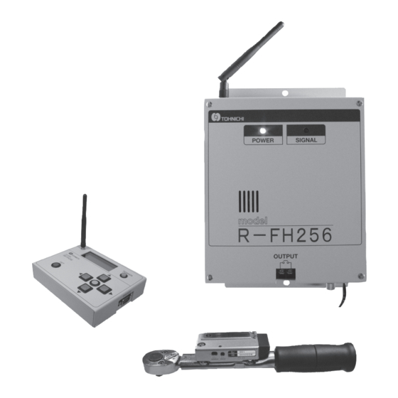
Page 8: Components
Components Transmitter Small transmitter T-FH256MC T-FHSLS256 Torque wrench QSPFH50N3 Torque wrench Slip type QSPCAFHS6N and torque QLFHSLS25N5 screwdriver RTDFHS260CN are also Wireless available. Setting BOX SB-FH256 Wireless Wired RS232C Wired Setting data Relay contact output The multicontact box Count checker... -
Page 9: Specifications
Specifications Transmitter Receiver Setting BOX Transmitter (for LS) Model T-FH256MC R-FH256 SB-FH256 T-FHSLS256 Frequency Band 2.4 GHZ band (2.402 GHz to 2.479 GHz, 1 MHz interval, 78 kinds) Output Power 1.5mW Communication System Spread spectrum (frequency hopping system) Modulation System... -
Page 10: External View And Each Part Name
External View and Each Part Name 5-1. External view of transmitter (T-FH256MC) and each part name Antenna holder Battery cover T-FH256MC Communication status check LED Channel plate Check switch Setting mode switch • Battery cover The battery cover is removed before the battery is changed. -
Page 11: External View Of Transmitter (T-Fhsls256) And Each Function
5-2. External view of transmitter (T-FHSLS256) and each function Channel plate Check switch Setting mode switch Communication status check LED • Communication status check LED When communication with the receiver is normal, the LED lights up in blue. When a communication error occurs, the LED flashes on and off in red 3 times. -
Page 12: External View Of Receiver (R-Fh256) And Each Part Name
5-3. External view of receiver (R-FH256) and each part name • Dipole Antenna connector Dipole antenna connector This is used to connect a dipole antenna. • Power LED When the power switch is turned ON, the LED lights up. • Receiving LED Receiving LED Power LED When a signal from the torque... -
Page 13: External View Of Setting Box (Sb-Fh256) And Each Part Name
• GET switch This is used to check the data (group, judgment code or 3-digit ID) currently set on the Transmitter (T-FH256MC, T-FHSLS256) and the Receiver (R-FH256). • SET switch This is used to send new data (group, judgment code, 3-digit ID) to be set to the Transmitter (T-FH256MC, T-FHSLS256) or the Receiver (R-FH256). -
Page 14: Precautions For Use
Precautions for Use 6-1. Power source (1) Be sure to use an AAA alkaline battery for the Transmitter (T-FH256MC). Be sure to use the Panasonic-made coin type lithium battery CR2032 as a power supply to the transmitter (T-FHSLS256). (2) Be sure to use the Receiver (R-FH256) within the range of AC100 to 240V (50/60Hz). - Page 15 (4) Set the load of the contact output within the rated load. (Relay output rating: DC30V 1A, AC125V 0.5A) The above rated contact capacity is according to resistance load. Some kinds of loads have a big difference between the steady-state current and the inrush current. Typical loads and inrush currents are as follows: Kind of load Inrush current...
-
Page 16: Handling
(3) When the adjusting screw of a preset and pre-lock type torque wrench is adjusted, the switch function of the transmitter may not operate properly. The stud of the torque wrench must be changed. Contact your nearest distributor or TOHNICHI MFG. CO., LTD. 7-2. Check of battery life and communication test of transmitter (T-FH256MC) (1) Press the Check switch on the side panel of the transmitter using a thin rod to turn ON. -
Page 17: Change Of Battery Of Transmitter (T-Fh256Mc)
7-3. Change of battery for transmitter (T-FH256MC) Preparation Torque screwdriver (Ex. RTD120CN (Hex bit B-W1.5...Catalog No.57)) (1) Loosen the 2 screws on the battery cover and remove the battery cover. * The 2 screws are not detached from the battery cover. -
Page 18: Replacement Of Vibration-Proof Sheets For Transmitter (T-Fhsls256)
7-5. Replacement of vibration-proof sheets for transmitter (T-FHSLS256) The T-FHSLS256 uses vibration-proof sheets in order to alleviate an impact to the substrate. To maintain shock resistance, it is necessary to replace the vibration-proof sheets every 3 years. Vibration-proof sheet 1 (for pasting to the substrate): 01T201218 Vibration-proof sheet 2 (for pasting to the base): 02T201218 1. -
Page 19: Setting Of Double Tightening Prevention Timer Of Receiver (R-Fh256)
8bit Stop bit 1bit Flow control CTS/RTS * Any setting other than the above is available. For details, contact your nearest distributor or TOHNICHI MFG. CO., LTD. (2) Data Format Header 7-digit alphanumeric Delimiter (000 to 999) (blank when not set) (3) Connection cable For connection with PC, PLC, etc. -
Page 20: Handling Of Setting Box (Sb-Fh256) (Check And Change Of Group, Judgment Code And Id)
7-9. Handling of setting BOX (SB-FH256) (Check and change of group, judgment code and ID) * Do not simultaneously operate the Transmitter (T-FH256MC,T-FHSLS256) and the Receiver (R-FH256). 7-9-1. Preparation of setting BOX Dipole antenna connector Display Power switch UP switch... - Page 21 7-9-2. Check and change of transmitter (1) Set the setting mode switch of the Transmitter to the setting mode position. (The communication status check LED flashes in red.) Setting mode switch In the left position, the setting mode is set. (2) Press the GET switch to display the current setting status.
-
Page 22: Change Of Battery Of Setting Box (Sb-Fh256)
7-9-3. Check and change of receiver (1) Set the setting mode switch of the Receiver to the setting mode position. (The SIGNAL LED will flash on and off.) Setting mode switch (PUSH LOCK) (2) Press the GET switch to display Upper column: Current setting the current setting status. -
Page 23: Installation Of Transmitter (T-Fh256Mc) To Your Torque Wrench
(2) Remove the battery cover of the Transmitter T-FH256MC to be installed. * The 2 screws are not detached from the battery cover. (3) Install the Transmitter T-FH256MC and tighten the 2 mounting screws using the torque screwdriver. (Tightening torque: T=270cN·m) * When installing the Transmitter, be careful that the stud is not placed between the leaf spring and the battery case. -
Page 24: Replacement Of Old Model Transmitter (F-Fm96Mc)
LED lights up in blue. 7-12. Replacement of old model transmitter (F-FM96MC) Preparation 1. Your FM torque wrench 2. Transmitter T-FH256MC 3. Receiver R-FH256 4. Torque screwdriver (Ex. RTD120CN (Hex bit B-W1.5...Catalog No.57)) 5. Torque screwdriver (Ex. RTD500CN (Hex bit B-W3...Catalog No.60)) (1) Loosen the 2 mounting screws on the old transmitter and remove the old transmitter. - Page 25 (3) Remove the battery cover of the new Transmitter T-FH256MC to be installed. * The 2 screws are not detached from the battery cover. (4) Install the new Transmitter T-FH256MC and tighten the 2 mounting screws with the torque screwdriver. (Tightening torque: T=270cN·m) * When installing the Transmitter, be careful that the stud is not placed between the leaf spring and the battery case.
-
Page 26: Installation On Ls Torque Wrench (T-Fh256Mcls)
7-13. Installation on LS torque wrench (T-FH256MCLS) Preparation 1. Your LS torque wrench 2. Transmitter T-FH256MC 3. Receiver R-FH256 4. Torque screwdriver (Ex. RTD120CN (Hex bit B-W1.5...Catalog No.57)) 5. Torque screwdriver (Ex. RTD500CN (Hex bit B-W3...Catalog No.60)) 6. Philips-head screwdriver (1) Loosen the 4 mounting screws on the LS switch cover and remove the LS switch cover. - Page 27 (5) Remove the battery cover of the Transmitter to be installed. * The 2 screws are not detached from the battery cover. (6) Insert the connector of the Limit switch to the connector on the Transmitter substrate. (7) Install the Transmitter and tighten the 2 mounting screws with the torque screwdriver.
-
Page 28: Installation On Ls Torque Wrench (T-Fhsls256)
7-14. Installation on LS torque wrench (T-FHSLS256) Preparation 1. Your LS torque wrench 2. Transmitter T-FHSLS256 3. Receiver R-FH256 4. Setting BOX SB-FH256 5. Torque screwdriver (Ex. RTD120CN (Hex bit W1.5 (Catalog No.57)) 6. Torque screwdriver (Ex. RTD500CN (Minus bit 0.9mm (Catalog No.89)) 7. - Page 29 made by ThreeBond recommended) to the threads and use the torque screwdriver to tighten. (T=25cN·m) * Be sure to insert washers between the Limit switch and the bolts. * Note that a cord may be disconnected by pulling it hard. (Adequate) (Pressed too much) Stud...
-
Page 30: Installation From Transmitter (T-Fh256Mcls)
7-15. Installation from transmitter (T-FH256MCLS) Preparation 1. Your torque wrench on which the T-FH256MCLS has been installed 2. Transmitter T-FHSLS256 3. Receiver R-FH256 4. Setting BOX SB-FH256 5. Torque screwdriver (Ex. RTD120CN (Hex bit W1.5 (Catalog No.57)) 6. Torque screwdriver (Ex. RTD500CN (Minus bit 0.9mm (Catalog No.89)) 7. - Page 31 (6) Attach a Transmitter Limit switch (accessory) in alignment with the marked position, using switch mounting screws and washers (accessories). Apply a screw locking agent (TB1324N made by ThreeBond recommended) to the threads and use the torque screwdriver to tighten. (T=25cN·m) * Be sure to insert washers between the Limit switch and the bolts.
-
Page 32: Connection With Poka Patrol Cna-4Mk3
7-16. Connection with POKA PATROL CNA-4mk3 To connect the Receiver with the multi-functional counter POKA PATROL (CNA-4mk3), connect the OUTPUT terminal of the Receiver and the WRENCH No. terminal (one of Nos.1 to 4) and the COM terminal of the CNA-4mk3 using a 2-wire shielded cable. (Connect the shield wires to the GND terminals of the respective cases.) * The tightening torque of the terminal block is T=50cN·m. -
Page 33: Troubleshooting
Multiple models are set in the setting be changed. Set only one model to the setting mode. mode. * Periodically check the transmitting and receiving status. * If you have any question, contact your nearest distributor or TOHNICHI MFG. CO., LTD. -
Page 34: Dimensions
Dimensions Transmitter Transmitter T-FH256MC T-FHSLS256 Setting BOX SB-FH256 2Xφ6.5 POWER SIGNAL model R-FH256 OUTPUT TIMER SET BZ RS232C POWER Receiver R-FH256... -
Page 35: Appendix
To comply with FCC RF exposure compliance requirements, this device must not be co-located or operating in conjunction with any other antenna or transmitter. For T-FH256MC RF TRANSCEIVER This device complies with Part 15 of the FCC Rules. Operation is subject to the following two... - Page 36 Canada Regulatory Compliance Statement This Class B digital apparatus complies with Canadian ICES-003. Cet appareil numériqué de ia classe B est conformé à la norma NMB-003 du Canada. For Customers in Canada This device complies with RSS 210 of Industry Canada (IC). Operation is subject to the following two conditions: (1) this device may not cause interference, and (2) this device must accept any interference, including interference that may cause undesired...
- Page 37 Declaration of Conformity We, the under signed, Tohnichi Mfg. Co., Ltd., hereby declare that the following product: Description RF TRANSCEIVER Manufacturer TOHNICHI MFG. CO., LTD. Brand TOHNICHI Type T-FH256MC Is in conformity with all the provisions of the following EC directive(s) with meeting the related test standards: Directive 1999/5/EC (R&TTE Directive):...
- Page 38 Declaration of Conformity We, the under signed, Tohnichi Mfg. Co., Ltd., hereby declare that the following product: Description RF TERMINAL Manufacturer TOHNICHI MFG. CO., LTD. Brand TOHNICHI Type R-FH256 Is in conformity with all the provisions of the following EC directive(s) with meeting the related test standards: Directive 1999/5/EC (R&TTE Directive):...
- Page 39 Declaration of Conformity We, the under signed, Tohnichi Mfg. Co., Ltd., hereby declare that the following product: Description RF SETTING BOX Manufacturer TOHNICHI MFG. CO., LTD. Brand TOHNICHI Type SB-FH256 Is in conformity with all the provisions of the following EC directive(s) with meeting the related test standards: Directive 1999/5/EC (R&TTE Directive):...
- Page 40 TOHNICHI MFG. CO., LTD. TEL: +81-(0)3-3762-2455 FAX: +81-(0)3-3761-3852 2-12, Omori-kita, 2-Chome Ota-ku, Tokyo 143-0016, JAPAN E-mail: overseas@tohnichi.co.jp Website: http://tohnichi.jp N. V. TOHNICHI EUROPE S. A. TEL: +32-(0)16-606661 FAX: +32-(0)16-606675 Industrieweg 27 Boortmeerbeek, B-3190 Belgium E-mail: tohnichi-europe@online.be Website: http://www.tohnichi.be TOHNICHI AMERICA CORP.
Need help?
Do you have a question about the FH256MC and is the answer not in the manual?
Questions and answers