Table of Contents
Advertisement
Advertisement
Table of Contents

Related Manuals for Tohnichi T-FHM


Summary of Contents for Tohnichi T-FHM
- Page 1 MODEL : FHM/FH Operating Instruction To use this product properly and safely, please read this operating instruction carefully before use. If you have any question about the product and its operations, please contact your nearest distributor or Tohnichi Mfg. Co., Ltd.
-
Page 2: Safety Precaution
Should this instrument give out abnormal smell or catch fire during use, stop using it immediately and remove the AC adapter from the outlet. Then, move the instrument to a safe place and contact Tohnichi Mfg. Co., Ltd. • Be sure to use an AAA alkaline battery for power supply to the transmitter T-FHM/T-FH. - Page 3 • When the adjusting screw of a preset or pre-lock type torque wrench is adjusted, the switch function of the transmitter may not operate properly. In that case, the stud of the torque wrench must be changed. Contact your nearest distributor or Tohnichi Mfg. Co., Ltd.
-
Page 4: Table Of Contents
3. Pokayoke System Component 4. Specifications 5. External View and Each Part Name 5-1. External View and Each Part Name of T-FHM/T-FH and Previous Transmitters 5-2. External View and Each Part Name of T-FHSLS256 5-3. External View and Each Part Name of M-FH 6. -
Page 5: Outline
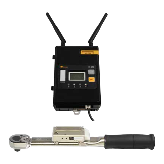
Outline By combining a remote signal transmitter T-FHM/T-FH with a Tohnichi torque wrench, a completion signal can be sent wirelessly to the receiver. Unlike wired LS torque wrenches, wireless wrench allows greater freedom of movement and ability to use the tool in places a wired tool cannot reach. With combination of R-CM receiver and T-FHM transmitter newly available battery monitoring function, and count checker functions for prevent missed tightening. - Page 6 • New and previous communication mode T-FHM can use AAA alkaline battery provides with available 4800 signals per day for 6 months or more. T-FHSLS: A CR2032 coin type lithium battery provides 3600 signals per day for 4 months or more.
-
Page 7: Pokayoke System Component
* Initial setting is required when replaced the radio module to communicate with the transmitter. • Battery alert, Time stamp function According to the settings of receiver and transmitter, outputs residual voltage value of transmitter T-FHM to R-CM and time stamp via RS232C terminal. By always monitoring the battery level and send signal when voltage drops to prevent interruption of the work. -
Page 8: Specifications
*2. For T-FH/T-FHM with a brand-new alkaline battery, about 650,000 tightening operations can be conducted. *3. For the battery life of the transmitter T-FHSLS256, FHP, and RTDFH/RNTDFH, tightening operation can be performed about 300,000 times with a new Panasonic-made coin type lithium battery CR2032. -
Page 9: External View And Each Part Name
Press it for 1 sec. to start to blinks in red and move to setting mode for checking or changing the group/judgment code/ID. Press the setting mode switch to return to normal mode. ●Channel plate If channels are specified when you order to Tohnichi, the group and ID will be marked on the plate. -
Page 10: External View And Each Part Name Of T-Fhsls256
Press the setting mode switch to return to normal mode. ● Channel plate If channels are specified when you order to Tohnichi, the group and ID will be marked on the plate. ● Remaining battery life notification function *T-FHSLS256, FHP, RTDFH/RNTDFH only When the battery level falls, communication status LED flashes 3 times alternately blue and red after regular operation. -
Page 11: External View And Each Part Name Of M-Fh
6-1. Power Source ! 1. Be sure to use AAA alkaline battery for the transmitter T-FH/T-FHM. For the transmitter T-FHSLS256, use Panasonic Coin type battery model CR2032. 2. Be sure to use DC 24 V for the R-CM power supply. -
Page 12: How To Attach M-Fh
6-3. How to Install radio module M-FH 1. Attach 2pcs of antenna on M-MH module. 2. Open the front cover of receiver and fit the module to the board. Take care not to pinch the metal fittings by the module. 3. -
Page 13: Error Messages
The stud of the torque wrench must be changed. Contact your nearest distributor or Tohnichi Mfg. Co., Ltd. 7-2. Check of Battery Life and Communication Test of Transmitters T-FHM/T-FH 1. Keep pressing the TEST button on the side panel of the transmitter. -
Page 14: Battery Replacement Of Tt-Fhm/T-Fh
7-3. Battery Replacement of T-FHM/T-FH Transmitter [Preparation] Torque screwdriver, e.g. RTD120CN and Hex bit B-W1.5...Catalog No. 57 1. Loosen the 2 screws and remove the battery cover. * The screws on the battery cover are adopted dropout prevention screw. 2 Replace the old battery to a new one. Make it sure in the correct direction of polarity. -
Page 15: Replacement Of Vibration-Proof Sheets Of T-Fhsls256/Fhp
7-4 Replacement of Vibration-proof Sheets for T-FHSLS256, FHP The T-FHSLS256 and FHP use vibration-proof sheets in order to alleviate an impact to the substrate. To maintain shock resistance, it is necessary to replace the vibration-proof sheets every 3 years. In case of T-FHSLS256 Vibration-proof sheet 1 : 01T201218, Vibration-proof sheet 2 : 02T201218 1 Replacement of vibration-proof sheet 1 1 Remove an old vibration-proof sheet from... -
Page 16: Rs232C Output Data Of M-Fh Module
7-6. Input/Output Format, RS232C Output for R-CM receiver with M-FH radio module 7-6-1. Communication Conditions Baud rate 2400/4800/9600/19200/38400/115200bps (Default : 9600bps) Default: 9600bps Parity None/Even/Odd Default: None (Default : None) Data length 7/8bit Default: 8 bit (Default : 8bit) Stop bit 1/2bit Default: 1 bit (Default : 1bit) -
Page 17: 7-6-3.Rs232C Input/Output Format For Parameter Settings
7-6-3. RS232CInput/Output Format for Setting Only when the receiver and the torque wrench are not communicating, the 3-digits ID and 7-digits ID of the receiver can be changed through RS232C communication. * When changing settings, select the contact output (R1 to R4) you want to change. PLC to R-CM ●3-digits ID (000 to 999) CR LF... -
Page 18: Communication Example
7-6-4. Communication Example 1. Communication confirmation command External Device Receiver Communication confirmation command CR LF Response CR LF 2. 3-digit ID request command (Setting: 3-digit ID at 001) External Device Receiver 3-digits ID Setting request command (R1) CR LF Response CR LF 3. -
Page 19: Count Checker Function
7-7. Usage Example of Count Checker Function Relay Terminal when the Count Checker ● Usage Example A function set at ON [Setting example] . Count over: NG IN1: RESET input . Preset judgment IN2: END input . Auto reset timer: OFF OUT1: OK signal out OUT2: NG signal out [Timing Chart]... -
Page 20: Setting Mode
* For setting confirmation by SB-FH2 setting box, refer to operating instruction of SB-FH2, "7 How to use". How to switch to setting mode of transmitter (T-FH/T-FHM and T-FHSLS256) 1. Press the SET switch for more than 1 second to enter setting mode. - Page 21 ● Communication Mode Select a communication mode of transmitter and receiver. R-CM(M-FH): advanced longer range signal, Battery monitoring functions are available. R-FH: Compatible the previous R-FH256 receiver's. Above new function is unavailable ● Group Selectable 000 to 255 of 256kinds of frequency channels ●...
- Page 22 ● B-ALM: Battery Residual Voltage 0.0 to 9.99V * Only for R-CM is set at R-CM(M-FH) mode Receiver alerts when the voltage drops less than setting value. Standard bland new AAA battery has 1.5v output and if the voltage drops below 0.9V, transmission will not be possible.
- Page 23 Setting Item Display Selection Default Communication Mode MODEL R-CM(M-FH), R-FH R-FH Group GROUP 000 - 255 Judgment Code 0, 1, 2, 3 3-digits ID ID1 - 4 000 - 999 Data Output Format STD, R-FH Baud Rate 2400, 4800, 9600, 19200, 38400, 115200bps 9600bps Parity NONE, ODD, EVEN...
-
Page 24: Sb-Fh Setting Screen
7-9-1. SB-FH Setting screen Setting process of SB-FH setting screen is as follows 1. Turn on the Setting Box and the next, turn on the receiver and keep pressing the SET button for 2 seconds, enter to setting mode. During setting mode, status lamp keep blinking. * In case using setting software, connect Setting Box SELECT button and a PC by a RS232C straight cable. -
Page 25: Model Setting
MODEL settings. 4. Communication mode 4. Communication mode setting screen Select an wireless communication mode. T-FHM is set on M-FH mode immediately. T-FH, T-FHW is available to change to M-FH by SB-FH2 setting box. Advanced signal mode: Previous signal mode : 5. - Page 26 6. Judgment code setting 5. Judgment code setting screen SELECT: Change the number SET: Save and move to #7 0: 3-digit ID, 7-digit alphanumeric characters without identification. 1: 3-digit ID with identification. 2: 7-digit alphanumeric characters with identification. 3: 3-digit ID, 7-digit alphanumeric characters with identification. 7.
-
Page 27: Base Setting
7-9-3. BASE setting Setting process of BASE setting screen is as follows 1. Turn on the receiver and keep pressing the SET button for 2 seconds to move to #2 Setting mode. SELECT button SET button 2. SET mode 2. Setting mode screen During the setting mode, the status lamp keep blinking blue. - Page 28 5. Baud rate setting 5. Select baud rate and move to the next SELECT: Select baud rate SET: Save and move to the next 96(9600bps)→192(19200bps)→384(38400bps)→1152 (115200bps) →24(2400bps) →48(4800bps) 6. Parity setting 6. Select parity and move to the next SELECT: Select parity SET: Save and move to #7 NONE →...
- Page 29 11. Double count prevention timer setting 11. Double count prevention timer setting SELECT: Change the number of digit from 0 to 9 SET: Save and move to the next digit Move to #12 when the left end of digit was set. 0.2 to 10.0 seconds 12.
- Page 30 15. Auto reset timer setting 15. Setting of auto reset timer SELECT: Change the number SET: Save and move to the next digit Move to the next setting when the left end of digit was set. 0.0 to 9.9 seconds 16.
-
Page 31: Quick Pairing Screen T-Fh/T-Fhm/Fhw With R-Cm Receiver
* Need a transmitter T-FHM/T-FH or T-FHW which have been set at M-FH mode. * Refer to 5-.1 External View and Each Part Name of T-FHM/T-FH and Previous Transmitters. * Check your transmitter whether it has been set at M-FH mode. - Page 32 4. OUT 1 Quick Paring 4. Relay output OUT1 of quick paring. SELECT: Choose a relay output from OUT 1 to 4. : Move to #5. * Up to 4 torque wrenches can be set by quick pairing. * Be sure to register the fist torque wrench on OUT1. *The second wrench can be set OUT2 to OUT4.
-
Page 33: Quick Paring For T-Fh, Previous Transmitters
R-CM receiver. * Previous transmitters models (T-FH256MC/T-FHSLS256/RTDFH/RNTDFH/FHP) and new T-FH/ T-FHM/FHW with R-FH mode is available for T-FH quick pairing. * Be sure to set the fist torque wrench on OUT1. * Refer to "5-1. for how to distinguish for new and previous transmitters. - Page 34 5. T-FH QUICK Paring 5. Starts Relay output OUT1 of quick paring. SELECT: Sift relay output from OUT 1 to 4, SET: Move to #6 * Up to 4 torque wrench can be set by quick pairing. * Be sure to register the fist torque wrench on OUT1. *The second wrench can be select from OUT2 to OUT4.
-
Page 35: Remote Setting Method Of R-Cm+M-Fh
7-10. Remote setting method of R-CM+M-FH "R-CM" receiver with "M-FH" radio module can be changed the setting remotely. The setting method is varies depending on the set mode, M-FH mode or R-FH mode. For M-FH mode, refer to operating manual of SB-FH2 setting box 7-2-3 Remote Setting. This section describes the remote setting when the communication mode of the receiver is set at R-FH, previous production mode. -
Page 36: Replacement Of Transmitter T-Fhm/T-Fh
1 Remove the battery cover of the transmitter on your FH torque wrench, loosen the 2 mounting screws and remove the transmitter. * The screws on the transmitter are adopted dropout prevention screw. 2 Remove the battery cover of the replacing Transmitter T-FHM/T-FH. * The screws on the battery cover are adopted dropout prevention screw. -
Page 37: Installation Of Transmitter T-Fhsls On Ls Torque Wrench
7-12. Installation of Transmitter T-FHSLS on LS Torque Wrench [Preparation] 1 Your LS torque wrench 2 Transmitter T-FHSLS256 3 Receiver R-CM and M-FH radio module 4 Setting BOX SB-FH2 5 Torque screwdriver e.g. RTD120CN, Hex bit B-W1.5...Catalog No.57 6 Torque screwdriver e.g. RTD500CN, Minus bit B-16...Catalog No.89 7 Philips-head screwdriver 1 Loosen the 4 mounting screws on the LS cover and LS Cover... - Page 38 5. Attach a Transmitter Limit switch (accessory) in alignment with the marked position, using switch mounting screws and washers (accessories). LS Cover Apply a screw locking agent (TB1324N) made by ThreeBond recommended) to the threads and use the torque screwdriver to tighten. *T=25cN·m * Be sure to insert washers between the Limit switch and the bolts.
-
Page 39: Settings With Setting Software
Settings with Setting Software 8. Settings with Setting Software T-FHW can be change setting items through dedicated setting software which Tohnichi provides. Prepare setting box SB-FH2 and RS232C straight cable and install the setting software to your PC. * System requirements OS: Windows 7 or later version Microsoft.NET Framework 4.0 or later version. - Page 40 3. Click “Next” to proceed the setup. 4. Click “Install”. Depending on OS system, the message "Do you want to allow the following program from an unknown publisher to make changes to this computer? is displayed. Click the [Install] to proceed with installation.
- Page 41 5. Installation has been completed. 6. When installation has been completed, a shortcut icon of "Pokayoke Tool Parameter setting Software" will appear on the desktop screen and startup menu.
- Page 42 * Trademarks Microsoft and Windows are registered trademarks of the Microsoft Corporation.
-
Page 43: How To Use Setting Software
8-2. How to use Setting Software ■Setting of R-CM+M-FH by SB-FH2 and setting software 1. Connect the setting box SB-FH2 to PC on which the Pokayoke Tool Parameter Setting Software has been installed with an RS232C straight cable, and turn on the setting box. * In case of previous product mode, power on the SB-FH2 and find "R-CM"... - Page 44 4. If it is not connected automatically, make sure that the setting box is power on, RS232C cable has been connecting firmly, and R-CM is in the setting mode, and then click "Reconnecting". 5. When "Connected" appears on the screen, select a tab of setting items.
- Page 45 6. By clicking "GET", the software receives current setting of R-CM+M-FH and displays it on the screen. ● Channel Setting [Description of various settings] - Relay output No. Select 1 to 8 *1. - Group 0: 3-digit ID, 7-digit alphanumeric characters without identification. - Judgment code *2 →When multiple torque wrenches are used with one receiver (applicable only when simultaneous transmission is not performed).
- Page 46 ●Communication settings 【Setting Explanation】 ・Data output format Select a RS232C data output format from STD/R-FH ・Baud rate 2400/4800/9600/19200/38400/115200 ・Parity None/Odd/Even ・Data length 7bit/8bit ・Stop bit 1bit/2bit ・Flow control Select CTS, RTS control OFF/ON...
- Page 47 【Other Settings】 ・Model selection R-CM(M-FH): Advanced mode, or R-FH mode: previous model mode ・Buzzer OFF/ON ・Double count prevention 0.0 to 10.0 seconds timer Timer starts when receive 1st signal and rejects following signals during on. 0.0 to 9.99V. *Only for R-CM(M-FH) mode setting. ・Battery voltage level Receiver alerts when the voltage drops less than setting value.
- Page 48 2. Refer to 7-8 and set the T-FHM/T-FH transmitter on set mode. 3. Boot setting software of the PC. If the PC is connected to the SB-FH2 with an RS232C straight cable and the T-FHM/T-FH is in the setting mode, it will automatically connect to the T-FHM/T-FH.
- Page 49 4. If not connected automatically, check whether SB-FH2 is power on, connecting condition of RS232C, T-FHM/T-FH mode is set, then click “Reconnect”. 5. When the message “Connected” is displayed, select the tab you want to change the setting item.
- Page 50 6. Click “GET” to receive the current settings of T-FHM/T-FH and display it in each item. ● Setting of transmitters 【Description of Setting items】 ・ Group Groups from 000 to 255 can be set. ・ Judgment code 0: 3-digit ID, 7-digit alphanumeric characters without identification.
- Page 51 7. Change the setting items and click "Send". The setting items are sent to T-FHM/T-FH via SB-FH2. 8. Settings are completed. Press SET button of T-FHM/T-FH transmitter to return to normal mode and conduct communication test. ■Language setting Click “Settings”, ”Language” to open language setting window.
-
Page 52: Dimensions
Dimensions Communication check LED Battery cover Antenna cover Communication check LED Test button Setting switch Transmitter Test button T-FHM / T-FH Setting switch Transmitter T-FHSLS256 71.2 Radio module M-FH... - Page 53 Serianl No. SELECT button SET button Display Receive LED x 4 status lamp Lever 48.5 97.2 Fegure of Receiver: R-CM with radio module M-MH...
-
Page 54: Trouble Shooting
Trouble Shooting Check the items in the table below before judging that the device has a breakdown. After checking the items, if the device still has a trouble, contact your nearest distributor or Tohnichi Mfg. Co., Ltd. Symptoms Causes Corrective actions Check the remaining battery life. - Page 56 ■Tohnichi Shanghai Mfg. Co., Ltd. 东仁扭矩仪器(上海)有限公司 Tel.+86 21 3407 4008 Fax.+86 21 3407 4135 RM.5 No.99 Nong1919, Du Hui Road, Minhang, Shanghai, P.R.China ● All rights reserved. No reproduction or republication without written permission. ● ©Tohnichi Mfg. Co., Ltd. All Rights Reserved. 10.19.EN.
Need help?
Do you have a question about the T-FHM and is the answer not in the manual?
Questions and answers