Table of Contents
Advertisement
Quick Links
Advertisement
Table of Contents

Related Manuals for AXIOMTEK FDK191-832


Summary of Contents for AXIOMTEK FDK191-832
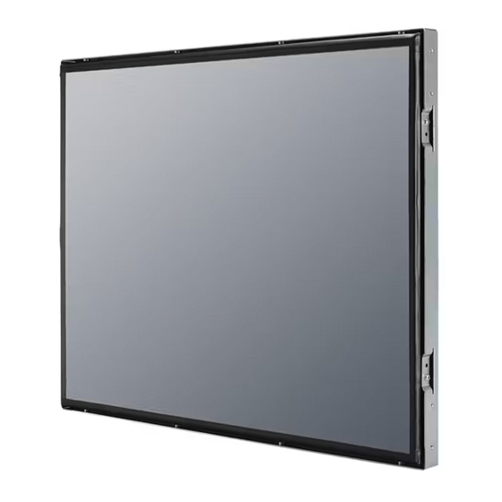
- Page 1 FDK191-832 Open Frame Display PANEL PC User’s Manual...
-
Page 2: Disclaimers
Axiomtek does not make any commitment to update the information in this manual. Axiomtek reserves the right to change or revise this document and/or product at any time without notice. No part of this document may be reproduced, stored in a retrieval system, or transmitted, in any form or by any means, electronic, mechanical, photocopying, recording, or otherwise, without the prior written permission of Axiomtek Co., Ltd. -
Page 3: Safety Precautions
When handling boards and components, wear a wrist-grounding strap, available from most electronic component stores. Trademarks Acknowledgments Axiomtek is a trademark of Axiomtek Co., Ltd. ® Windows is a trademark of Microsoft Corporation. IBM, PC/AT, PS/2, VGA are trademarks of International Business Machines Corporation. -
Page 4: Table Of Contents
Table of Contents Disclaimers ..................... ii Safety Precautions ..................iii Chapter 1 Introduction ..........1 General Description ................1 Specifications ..................2 Dimensions and Outlines ..............4 I/O Outlets .................... 6 Packing List ..................7 Chapter 2 Hardware and Installation ...... 9 Open and close back cover .............. - Page 5 Chapter 4 Drivers Installation ......41 System ....................41 Touch Screen ..................41...
- Page 6 This page is intentionally left blank.
-
Page 7: Chapter 1 Introduction
HMI automation, and many more applications. Its slim ID can fits into any space or encased in any chassis. FDK191-832 comes with a front panel open frame design. Other than offering above configuration advantages, this open frame panel computer series also highlights an ultra slim profile and compact footprint in thickness of 60mm for any space. -
Page 8: Specifications
FDK191-832 User’s Manual Specifications Main CPU Board ® Intel Atom D2550 1.86GHz processor onboard System Chipset ® Intel NM10 Express System Memory One 204-pin DDR3 1066MHz SO-DIMM socket Maximum memory up to 4GB ... - Page 9 FDK191-832 User’s Manual System Specification 19” SXGA(1280x1024) TFT LCD One VR for brightness control Touch (equip on FDK191-832-R models) 5-wired resistive touch Heat Dispensing Design Disk drive housing One 2.5” SATA drive ...
-
Page 10: Dimensions And Outlines
FDK191-832 User’s Manual Dimensions and Outlines The following diagrams show the dimensions and outlines of FDK191-832. Introduction... - Page 11 FDK191-832 User’s Manual Introduction...
-
Page 12: I/O Outlets
FDK191-832 User’s Manual I/O Outlets Please refer to the following illustration for I/O locations of the FDK191-832. Function Function POWER SWITCH (ATX) COM 2 (RS-232) 1 x 12VDC Power input connector or 2 X ETHERNET (RJ-45) 24V DC phoenix connector 2 X USB 2.0... -
Page 13: Packing List
Power cord x 1 Power adaptor x 1 (for 12V DC Power Jack type only) Phoenix terminal x 1 (for phoenix type only) If you can not find the package or any items are missing, please contact Axiomtek distributors immediately. Introduction... - Page 14 FDK191-832 User’s Manual This page is intentionally left blank. Introduction...
-
Page 15: Hardware And Installation
FDK191-832 User’s Manual Chapter 2 Hardware and Installation The FDK191-832 provides rich I/O ports and flexible expansions for you to meet different demand, for example CF card. The chapter will show you how to install the hardware. It includes: ... -
Page 16: Open And Close
FDK191-832 User’s Manual Open and close back cover This section tells users how to open and close the back cover. Please follow the steps below. Step 1 Unscrew eleven screws on the back cover. Please refer the photo of top side, right side and left side. - Page 17 FDK191-832 User’s Manual Step 2 When users open the back cover, there is a cable connecting between a fan and the motherboard. Step 3 Remove the connector first before remove the back cover totally. Hardware and Installation...
- Page 18 FDK191-832 User’s Manual Step 4 After removing the back cover, users can see the inside of the unit. Step 5 Before closing the back cover, users must connect the fan cable to the motherboard first. Step 6 Then close back cover and fix back the eleven screws.
-
Page 19: Cf Card Installation
Locate the CompactFlash socket, and insert the card into the socket. Serial Ports Interface The FDK191-832 has three serial ports. COM1 is RS-232/422/485, while COM2 and COM3 are RS-232. The following table shows you the pin assignments of this connector:... -
Page 20: Com1&Com2 Connector
FDK191-832 User’s Manual 2.3.1 COM1&COM2 Connector The COM1 and COM2 is a standard DB-9 connector. This connector is equipped with +5V level power capability on DCD and +12V level on RI by setting JP10 and JP11. Jumper Description Default Jumper Setting... -
Page 21: Ethernet
FDK191-832 User’s Manual Ethernet The FDK191-832 is equipped with a high performance Plug and Play Ethernet interface, full compliant with IEEE 802.3 standard, and can be connected with a RJ-45 LAN connector. Please refer to detailed pin assignment list below:... -
Page 22: Mountings: Openframe/Vesa
There are two mounting ways for the FDK191-832 series, openframe and VESA mountings. 2.5.1 Openframe Mount The FDK191-832 series can be mounted into the wall or put on customized front bezel. Please follow the steps below to for the open frame mounting installation. Step 1 Users need to prepare the front bezel/wall, screws, nuts, sponge, and L-type holders by themselves. -
Page 23: Vesa Mounting
2.5.2 VESA Mounting FDK191-832 series provides two types of VESA holes, 75mm x 75mm and 100mm x 100mm. These VESA holes can easy for users to install FDK191-832 series via many different types of VESA mounting holders, such as VESA arm, VESA wall holders…etc. -
Page 24: Hdd Installation
FDK191-832 User’s Manual HDD Installation The FDK191-832 provides a convenient Hard Disk Drive (HDD) bracket for users to install 2.5” SATA HDD. Please follow the steps: Step 1 Refer section 2.1 to open the back cover. Step 2 Unscrew 4 screws to take off the HDD bracket. - Page 25 FDK191-832 User’s Manual Step 4 Fix the HDD bracket into the system, and plug the data and power cable to HDD. Installation completes. Data Power Hardware and Installation...
-
Page 26: Dram Installation
FDK191-832 User’s Manual DRAM Installation The FDK191-832 provides one 204-pin DDR3 SODIMM socket that support system memory up to 4GB. Please follow steps below to install the memory modules: Step 1 Refer to section 2.1 to open the back cover and find out DIMM socket on mainboard (SBC87832). -
Page 27: Wireless Lan Card Installation
FDK191-832 User’s Manual Wireless LAN Card Installation The FDK191-832 provides one Mini card slot for user to install one wireless LAN card. When installing the wireless LAN card, refer to the following instructions and illustration: Step 1 Refer to section 2.1 to open the back cover and find out mini-card slot on mainboard. - Page 28 FDK191-832 User’s Manual Step 3 Remove the antenna plug from the top of back cover. Step 4 Install the antenna cable on the back cover. Step 5 Install the antenna on the antenna connector. Hardware and Installation...
- Page 29 FDK191-832 User’s Manual Step 6 Connect the antenna cable to wireless LAN card. Hardware and Installation...
- Page 30 FDK191-832 User’s Manual This page is intentionally left blank. Hardware and Installation...
-
Page 31: Ami Bios Setup Utility
FDK191-832 User’s Manual Chapter 3 AMI BIOS Setup Utility This chapter provides users with detailed description how to set up basic system configuration through the AMIBIOS8 BIOS setup utility. Starting To enter the setup screens, follow the steps below: Turn on the computer and press the <Del> key immediately. -
Page 32: Main Menu
FDK191-832 User’s Manual Main Menu When you first enter the Setup Utility, you will enter the Main setup screen. You can always return to the Main setup screen by selecting the Main tab. There are two Main Setup options. They are described in this section. The Main BIOS Setup screen is shown below ... -
Page 33: Advanced Menu
FDK191-832 User’s Manual Advanced Menu Launch Storage OpROM This item can enable or disable boot option for legacy mass storage devices with option ROM. The Advanced menu also allows users to set configuration of the CPU and other system devices. - Page 34 FDK191-832 User’s Manual ACPI Settings You can use this screen to select options for the ACPI Configuration, and change the value of the selected option. A description of the selected item appears on the right side of the screen.
- Page 35 FDK191-832 User’s Manual CPU Configuration This screen shows the CPU Configuration, and you can change the value of the selected option. Hyper-Threading Use this item to enable or disable Hyper-Threading Technology, which makes a single physical processor perform multi-tasking function as two logical ones.
- Page 36 FDK191-832 User’s Manual IDE Configuration SATA Controller(s) The optional settings are: [Disabled]; [Enabled]. Configure SATA as The optional settings are: [IDE]; [AHCI]. AMI BIOS Setup Utility...
- Page 37 FDK191-832 User’s Manual USB Configuration You can use this screen to select options for the USB Configuration, and change the value of the selected option. A description of the selected item appears on the right side of the screen.
- Page 38 FDK191-832 User’s Manual NCT6627UD Super IO Configuration You can use this screen to select options for the Super IO Configuration, and change the value of the selected option. A description of the selected item appears on the right side of the...
- Page 39 FDK191-832 User’s Manual PC Health Status This screen shows the Hardware Health Configuration, and a description of the selected item appears on the right side of the screen. AMI BIOS Setup Utility...
-
Page 40: Chipset Menu
FDK191-832 User’s Manual Chipset Menu The Chipset menu allows users to change the advanced chipset settings. You can select any of the items in the left frame of the screen to go to the sub menus: ► Host Bridge Host Bridge For items marked with “”, please press <Enter> for more options. - Page 41 FDK191-832 User’s Manual Memory Information This item is for memory frequency and timing settings. Press <Enter> to go to the sub menu. AMI BIOS Setup Utility...
-
Page 42: Boot Menu
FDK191-832 User’s Manual Boot Menu The Boot menu allows users to change boot options of the system. Boot Settings Configuration Setup Prompt Timeout Use this item to set number of seconds to wait for setup activation key. Bootup NumLock State Use this item to select the power-on state for the NumLock.. -
Page 43: Security Menu
FDK191-832 User’s Manual Security Menu The Security menu allows users to change the security settings for the system. Administrator Password This item indicates whether an administrator password has been set. If the password has been installed, Installed displays. If not, Not Installed displays. -
Page 44: Save & Exit Menu
FDK191-832 User’s Manual Save & Exit Menu The Save & Exit menu allows users to load your system configuration with optimal or fail-safe default values. Save Changes and Exit When you have completed the system configuration changes, select this option to leave Setup and reboot the computer so the new system configuration parameters can take effect. - Page 45 FDK191-832 User’s Manual Discard Changes Select this option to quit Setup without making any permanent changes to the system configuration. Select Discard Changes from the Save & Exit menu and press <Enter>. Select Yes to discard changes. Restore Defaults It automatically sets all Setup options to a complete set of default settings when you select this option.
- Page 46 FDK191-832 User’s Manual This page is intentionally left blank. AMI BIOS Setup Utility...
-
Page 47: Drivers Installation
Chapter 4 Drivers Installation System FDK191-832 supports Windows 7 32-bit and WES 7. To facilitate the installation of system driver, please carefully read the instructions in this chapter before start installing. Insert Driver CD and select the “\Drivers”. Step 1 Step 2 Select all files and follow the installing procedure. - Page 48 Driver Installation- Windows 7 The FDK191-832 provides a touch screen driver that users can install it under the operating system Windows 7. To facilitate installation of the touch screen driver, you should read the instructions in this chapter carefully before you attempt installation.
- Page 49 FDK191-832 User’s Manual Step 5 Calibration: To adjust the display with touch panel, click “Calibration” and follow the calibrate point to do calibration; there are five points on screen for calibration. Step 6 Press OK. Drivers Installation...
- Page 50 FDK191-832 User’s Manual page is intentionally left blank. Drivers Installation...
Need help?
Do you have a question about the FDK191-832 and is the answer not in the manual?
Questions and answers