Table of Contents
Advertisement
Quick Links
This manual contains text, diagrams and explanations which will guide the reader in the correct installation
and operation of the FX
attempting to install or use the unit.
Further information can be found in the FX PROGRAMMING MANUAL(ΙΙ) and FX
FX
SERIES HARDWARE MANUAL.
3U
Guidelines for the Safety of the User and Protection of the FX
special function block.
This manual should be used by trained and competent personnel. The definition of such a person or
persons is as follows:
a) Any engineer using the product associated with this manual, should be of a competent nature,
trained and qualified to the local and national standards. These engineers should be fully aware of
all aspects of safety with regards to automated equipment.
b) Any commissioning or service engineer must be of a competent nature, trained and qualified to
the local and national standards.
c) All operators of the completed equipment should be trained to use this product in a safe and
coordinated manner in compliance to established safety practices.
Note: The term 'completed equipment' refers to a third party constructed device which contains or uses
the product associated with this manual.
Notes on the Symbols Used in this Manual
At various times throughout this manual certain symbols will be used to highlight points of information
which are intended to ensure the users personal safety and protect the integrity of equipment.
1) Indicates that the identified danger WILL cause physical and property damage.
2) Indicates that the identified danger could POSSIBLY cause physical and property
damage.
•
Under no circumstances will Mitsubishi Electric be liable or responsible for any consequential damage
that may arise as a result of the installation or use of this equipment.
•
All examples and diagrams shown in this manual are intended only as an aid to understanding the
text, not to guarantee operation. Mitsubishi Electric will accept no responsibility for the actual use of
the product based on these illustrative examples.
•
Owing to the very great variety in possible application for this equipment, you must satisfy yourself as
to its suitability for your specific application.
1. INTRODUCTION
•
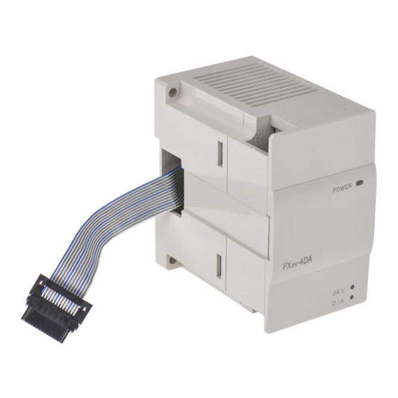
The FX
-4DA analog special function block has four analog output channels. The output channels
2N
take a digital value and output an equivalent analog signal. This is known as a D/A conversion. The
FX
-4DA has a maximum resolution of 12 bits.
2N
•
The selection of voltage or current based input/output is by user wiring. Analog ranges of -10 to 10V
DC (resolution: 5mV), and/or 0 to 20mA (resolution: 20µA) maybe selected independently for each
channel.
•
The FX
-4DA can connected to the FX
2N
(PLC).
•
Data transfer between the FX
are 32 buffer memories (each of 16 bits) in the FX
•
The FX
-4DA occupies 8 I/O points on the FX
2N
from either inputs or outputs. The FX
extension unit.
FX
-4DA special function block and should be read and understood before
2N
0N
-4DA and the main unit is completed buffer memory exchange. There
2N
-4DA draws 30mA from the 5V rail of the main unit or powered
2N
-4DA SPECIAL FUNCTION BLOCK
2N
USER'S GUIDE
/FX
/FX
/FX
/FX
1N
2N
2NC
-4DA.
2N
expansion bus. The 8 I/O points can be allocated
2N
JY992D65901C
/FX
0N
series Programmable Controllers
3U
/FX
/FX
/
1N
2N
2NC
-4DA
2N
Advertisement
Table of Contents
Troubleshooting

Related Manuals for Mitsubishi FX2N-4DA


Summary of Contents for Mitsubishi FX2N-4DA
- Page 1 All examples and diagrams shown in this manual are intended only as an aid to understanding the text, not to guarantee operation. Mitsubishi Electric will accept no responsibility for the actual use of the product based on these illustrative examples.
- Page 2 2. EXTERNAL DIMENSIONS AND PARTS Dimensions: mm (inches) 8 7 ( 3 . 4 3 ) 5 5 ( 2 . 1 7 ) 5 5 ( 2 . 1 7 ) 4 ( 0 . 1 6 ) P O W E R 2 4 V D / A 9 ( 0 .
- Page 3 5. SPECIFICATIONS 5.1 General specifications Item Specification General specifications Same as those for the main unit Dielectric withstand voltage 500V AC, 1min (between all terminals and ground) 5.2 Performance specification Item Centigrade Fahrenheit -10V DC to +10V DC (External load DC 0mA to +20mA (External load Analog output range resistance: 2kΩ...
- Page 4 3) [BFM #5]: Data holding mode: While the programmable controller is in the STOP mode, the last output value in the RUN mode will be held. To reset the value to the offset value, write the hexadecimal value in BFM #5 as follows: O = 0: Holds the output.
- Page 5 Note: BFM #’s marked E. • Values of BFM #0, #5, and #21, (marked E) are stored in the EEPROM memory of the FX -4DA. BFM #10 to #17 are copied to EEPROM when the gain/offset setting command BFM #8, #9 is used. Also, BFM #20 causes the resetting of the EEPROM memory.
- Page 6 This manual confers no industrial property rights or any rights of any other kind, nor does it confer any patent licenses. Mitsubishi Electric Corporation cannot be held responsible for any problems involving industrial property rights which may occur as a result of using the contents noted in this manual.
- Page 7 All examples and diagrams shown in this manual are intended only as an aid to understanding the text, not to guarantee operation. Mitsubishi Electric will accept no responsibility for the actual use of : The maximum connectable units is 4.
- Page 8 This manual confers no industrial property rights or any rights of any other kind, nor does it confer any (turned on) (turned off) 9.1 I/O characteristics patent licenses. Mitsubishi Electric Corporation cannot be held responsible for any problems involving Error Error if any of b1 through b4 is turned on No error industrial property rights which may occur as a result of using the contents noted in this manual.
Need help?
Do you have a question about the FX2N-4DA and is the answer not in the manual?
Questions and answers