Table of Contents
Advertisement
Quick Links
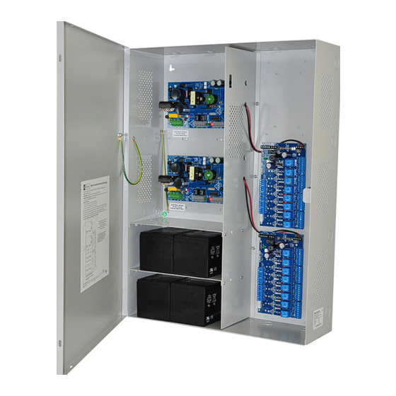
Access Power Controllers
with Power Supplies
Installation Guide for models:
Maximal11FD
- Power Supply 1:
12VDC @ 3.3 amp or 24VDC @ 3.6 amp.
- Power Supply 2:
12VDC @ 3.3 amp or 24VDC @ 3.6 amp.
- Sixteen (16) PTC protected
power-limited outputs.
Maximal33FD
- Power Supply 1:
12VDC @ 5.3 amp or 24VDC @ 5.6 amp.
- Power Supply 2:
12VDC @ 5.3 amp or 24VDC @ 5.6 amp.
- Sixteen (16) PTC protected
power-limited outputs.
Rev. DFD051613
Installing Company: _____________________ Service Rep. Name: __________________________________________
Address: ________________________________________________________ Phone #: _________________________
- Power Supply 1: 12VDC @ 9.3 amp.
- Power Supply 2: 12VDC @ 9.3 amp.
- Sixteen (16) PTC protected
Maximal77FD
- Power Supply 1: 24VDC @ 9.6 amp.
- Power Supply 2: 24VDC @ 9.6 amp.
- Sixteen (16) PTC protected
Maximal75FD
- Power Supply 1: 12VDC @ 9.3 amp.
- Power Supply 2: 24VDC @ 9.6 amp.
- Sixteen (16) PTC protected
Altronix Corp.
140 58th St. Brooklyn, NY
Maximal55FD
power-limited outputs.
power-limited outputs.
power-limited outputs.
More than just power.™
Advertisement
Table of Contents

Related Manuals for Altronix Maximal11FD


Summary of Contents for Altronix Maximal11FD
- Page 1 Access Power Controllers with Power Supplies Installation Guide for models: Maximal11FD Maximal55FD - Power Supply 1: - Power Supply 1: 12VDC @ 9.3 amp. 12VDC @ 3.3 amp or 24VDC @ 3.6 amp. - Power Supply 2: 12VDC @ 9.3 amp.
- Page 2 CSA C22.2 No.205 - Signal Equipment. ULC-S319-05 Electronic Access Control Systems will be invalidated through the use of any add-on, expansion, memory or other module manufactured by the manufacturer or other manufacturers. Maximal11FD/Maximal33FD/Maximal55FD/Maximal77FD/Maximal75FD Access Power Controllers (PTC) - 2 -...
- Page 3 Remove the enclosure. Drill the lower holes and install the three fasteners. Place the enclosure’s upper keyholes over the three upper screws. Install the three lower screws and make sure to tighten all screws (Enclosure Dimensions, pg. 12). - 3 - Maximal11FD/Maximal33FD/Maximal55FD/Maximal77FD/Maximal75FD Access Power Controllers (PTC)
- Page 4 There are no user serviceable parts inside. Refer installation and servicing to qualified service personnel. 3. Select desired DC output voltage by setting SW1 to the appropriate position on the power supply board (Maximal11FD and Maximal33FD), (Fig. 1, pg. 7). Maximal55FD power supply is factory set at 12VDC. Maximal77FD power supply is factory set at 24VDC.
-
Page 5: Maintenance
Normal operating condition. Battery fail/low battery. Access Power Controller LED Diagnostics: LED 1- LED 8 (Red) Output relay(s) energized. Output relay(s) de-energized. Trg (Green) FACP input triggered (alarm condition). FACP normal (non-alarm condition). - 5 - Maximal11FD/Maximal33FD/Maximal55FD/Maximal77FD/Maximal75FD Access Power Controllers (PTC) -
Page 6: Power Supply Board Terminal Identification
12VDC to 24VDC trigger controlled outputs. Maximum load per output is 2 amp. Maximal11FD: P/S 1 - 9.8-13.2VDC @ 3.3 amp P/S 2 - 9.8-13.2VDC @ 3.3 amp or P/S 1 - 19.9-26.4VDC @ 3.6 amp P/S 2 - 19.9-26.4VDC @ 3.6 amp or P/S 1 - 9.8-13.2VDC @ 3.3 amp and P/S 2 - 19.9-26.4VDC @ 3.6 amp. -
Page 7: Power Supply Board Stand-By Battery Specifications
OUTPUT 5 OUTPUT 6 OUTPUT 7 OUTPUT 8 FACTORY POWER WIRED TO SUPPLY UL Listed eFLOW (Not evaluated ELECTRIC POWER SUPPLY POWER SUPPLY by UL) STRIKE MAG. LOCK ELECTROMAGNETIC DOOR HOLDERS Fig. 2b - 7 - Maximal11FD/Maximal33FD/Maximal55FD/Maximal77FD/Maximal75FD Access Power Controllers (PTC) - Page 8 Enclosure listed external battery enclosure must be Edge of (Not Included) Enclosure used if using the 40AH or 65AH batteries. Fig. 3a to Access Control Panel or U.L. Listed Reporting Device Maximal11FD/Maximal33FD/Maximal55FD/Maximal77FD/Maximal75FD Access Power Controllers (PTC) - 8 -...
- Page 9 Power-limited Battery Connections (non power-limited) Fig. 4a Incorrect Wire Correct Wire Handling Handling Supervisory External Connections Jacketed (power-limited) Shield Wire Insulation Pull back Solid Copper external jacketed Conductors shield approx. 1/2”. - 9 - Maximal11FD/Maximal33FD/Maximal55FD/Maximal77FD/Maximal75FD Access Power Controllers (PTC)
-
Page 10: Facp Hook-Up Diagrams
FACP Hook-up Diagrams: Fig. 5 Optional hook-up using two (2) isolated power Fig. 6 Polarity reversal input from FACP signaling circuit supply inputs (Only applicable on Maximal11FD) output (polarity is referenced in alarm condition): (Not evaluated by UL): JUMPER J3... - Page 11 Notes: - 11 - Maximal11FD/Maximal33FD/Maximal55FD/Maximal77FD/Maximal75FD Access Power Controllers (PTC)
-
Page 12: Enclosure Dimensions
19” (482.6mm) Altronix is not responsible for any typographical errors. 140 58th Street, Brooklyn, New York 11220 USA, 718-567-8181, fax: 718-567-9056 web site: www.altronix.com, e-mail: info@altronix.com, Lifetime Warranty, Made in U.S.A. MEMBER IIMaximal11FD/33FD/55FD/75FD/77FD Series F06N Maximal11FD/Maximal33FD/Maximal55FD/Maximal77FD/Maximal75FD Access Power Controllers (PTC)
Need help?
Do you have a question about the Maximal11FD and is the answer not in the manual?
Questions and answers