Table of Contents
Advertisement
Quick Links
On-Demand Water Heater
Installation Manual and Owner's Guide
R
ANSI Z21.10.3 ・ CSA 4.3
Models
• 110 Indoor
• 310 Indoor
• 510 Indoor
Gas Tankless Water Heater
Suitable for combination potable water heating
and space heating. Please refer to local codes for
space-heating compliance.
FEATURING
• ENDLESS HOT WATER
• ON-DEMAND USAGE
• COMPACT, SPACE SAVING
• ENERGY CONSERVATION
• COMPUTERIZED SAFETY
• NO PILOT LIGHT
• EASY-LINK SYSTEM
510 model only
• Complies with natural gas Low
NOx emissions of 40 ng/J or
55 ppm.
Keep this manual near the water heater for future reference whenever maintenance, adjustment, or
service is required.
D
R
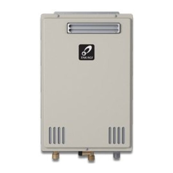
• 110 Outdoor
(USA Only)
• 310 Outdoor
(USA Only)
• 510 Outdoor
(USA Only)
TM
510
model only
If the information in these
instructions is not followed
exactly, a fire or explosion may
result causing property damage,
WARNING
personal injury or death.
- Do not store or use gasoline or other
flammable vapors and liquids in the vicinity
of this or any other appliance.
- WHAT TO DO IF YOU SMELL GAS
• Do not try to light any appliance.
• Do not touch any electric switch, do not
use any phone in your building.
• Immediately call your gas supplier from
a neighbor's phone. Follow the gas
supplier's instructions.
• If you cannot reach your gas supplier, call
the fire department.
- Installation and service must be performed
by a qualified installer, service agency or the
gas supplier.
If you have any questions,
please call or write to:
In the United States
500 Tennessee Waltz Parkway
Ashland City, TN 37015
Toll Free: 1-877-737-2840
599 Hill Street West
Fergus, ON N1M 2X1
1-888-479-8324
In Canada
Advertisement
Table of Contents

Related Manuals for Takagi 110 Outdoor


Summary of Contents for Takagi 110 Outdoor
- Page 1 On-Demand Water Heater Installation Manual and Owner’s Guide ANSI Z21.10.3 ・ CSA 4.3 model only Models If the information in these instructions is not followed • 110 Indoor • 110 Outdoor exactly, a fire or explosion may (USA Only) • 310 Indoor • 310 Outdoor result causing property damage, WARNING (USA Only) personal injury or death. • 510 Indoor • 510 Outdoor (USA Only) - Do not store or use gasoline or other flammable vapors and liquids in the vicinity...
-
Page 2: Table Of Contents
Contents CONTENTS Owner's Guide Installation Manual OPERATING SAFETY ........35 SPECIFICATIONS ..........4 INTRODUCTION ..........5 NORMAL OPERATION ........37 SAFETY GUIDELINES........6 GENERAL ............37 SAFETY DEFINITION ........6 TEMPERATURE SETTINGS ......37 GENERAL ............6 OTHER FEATURES OF THE REMOTE INSTALLATION ..........7 CONTROLLERS ...........39 GENERAL ............7 TEMPERATURE SETTINGS ON THE PCB ..41 CLEARANCES ..........9 FLOW ............ -
Page 3: Installation Manual
Installation Manual Installation Manual CONGRATULATIONS Congratulations and thank you for choosing our tankless water heater. Before use, we recommend that you read through this installation manual carefully. Keep this manual for future reference. If you need an additional manual, contact the manufacturer or your local distributor. -
Page 4: Specifications
Installation Manual Specifications SPECIFICATIONS Model Indoor Outdoor Indoor Outdoor Indoor Outdoor Natural Gas Input Min.: 19,500 Min.: 11,000 Min.: 11,000 BTU/h (Operating Range) Max.: 140,000 Max.: 190,000 Max.: 199,000 Propane Gas Input Min.: 19,500 Min.: 11,000 Min.: 11,000 BTU/h (Operating Range) Max.: 140,000 Max.: 190,000 Max.: 199,000... -
Page 5: Introduction
• The 110 Indoor, 310 Indoor, and 510 Indoor models are only to be installed indoors (direct- vent convertible). The 110 Outdoor, 310 Outdoor, and 510 Outdoor models are only to be installed outdoors. • The principle behind tankless water heaters is simple:... -
Page 6: Safety Guidelines
Installation Manual Safety Guidelines SAFETY GUIDELINES SAFETY DEFINITION Indicates an imminently hazardous situation which, if not avoided, will result in death or serious injury. DANGER Indicates an imminently hazardous situation which, if not avoided, could result in death or seri- ous injury. -
Page 7: Installation
Terminating the exhaust and intake on the same wall/surface is recommended. Terminating in the same pressure zone allows for pressure balancing, which prevents nuisance shutdowns. 11. 110 Outdoor, 310 Outdoor, and 510 Outdoor models are only to be installed outdoors and only in areas with mild, temperate climates. - Page 8 Installation Manual Installation • Installation and service must be performed by a qualified installer (for example, a licensed plumber or gas fitter). Otherwise, the warranty will be void. • The installer (licensed professional) is responsible for the correct installation of the water heater and for compliance with all national, state/provincial, and local codes.
-
Page 9: Clearances
4 in.* 1 in. 3 in. 310 Indoor (305 mm) (305 mm) (102 mm) (25 mm) (76 mm) 510 Indoor 110 Outdoor 36 in. 12 in. 24 in. 1 in. 3 in. 310 Outdoor (914 mm) (305 mm) (610 mm) - Page 10 Installation Manual Installation 1. 4” Backflow preventer and F-F adaptor: 2. Direct-vent conversion kit: 100112184 100112416 (TK-TV10) There are two functions available for this adaptor, which can be connected with the This kit can be used water heater and NovaVent venting line to convert the water and prevents the backflow of air through heater from a single...
-
Page 11: Warning For Installations
Installation Manual Installation WARNING FOR INSTALLATIONS FOR YOUR SAFETY, READ BEFORE INSTALLATION: Do not install the heater where water, debris or Do not have the vent terminal pointing toward flammable vapors may get into the flue terminal. any opening into a building. Do not locate your This may cause damage to the heater and void the heater in a pit or location where gas and water warranty. -
Page 12: High-Altitude Installations
Installation Manual Installation HIGH-ALTITUDE INSTALLATIONS Check the altitude where your water heater is installed. Set DIP switches shown in the table below. The DIP switch settings depend on the altitude. • Adjust the appropriate DIP switches according to model and elevation as shown below. -
Page 13: Venting Instructions
Installation Manual Installation VENTING INSTRUCTIONS Indoor models -General- • Improper venting of this appliance can result in excessive levels of carbon monoxide which can result in severe personal injury or death. • Improper installation can cause nausea or asphyxiation, severe injury or death from carbon monoxide and flue gases poisoning. - Page 14 Installation Manual Installation • Do not common vent or connect any vent from other appliances to the water heater vent. General rules for vent terminations: • Avoid locating the water heater vent termination near any air intake devices. These fans can pick up the exhaust flue products from the water heater and return them to the building.
-
Page 15: Combustion Air Supply
Installation Manual Installation -Combustion air supply- The guidelines in this section apply to installations within the United States. All • U.S. installations must conform to the National Fuel Gas Code, ANSI Z223.1/NFPA NOTICE 54 (current edition) and local codes. • Canadian requirements differ from the guidelines in this section. - Page 16 Installation Manual Installation Your water heater’s BTU/h rating is on the rating plate. The BTU/h ratings should be on the other appliances’ rating plates. If you have trouble determining the BTU/h ratings, contact the manufacturer or have a qualified person determine the ventilation requirements. : If you are replacing your old water heater with one that has a higher BTU/h rating, the amount of NOTICE ventilation required may be greater.
- Page 17 Installation Manual Installation Determine type of ventilation There are several types of ventilation that can be used. The various options are listed below. See also the illustrations on the next page. 1. Direct to outdoors 2. Vertical ducts 3. Horizontal ducts 4.
- Page 18 Installation Manual Installation Combustion air supply options Gable vent to outdoors Install above insulation 12” (305 mm) Outlet air to Confined maximum attic 1 in (6.5 cm Space per 4,000 btu/h Two permanent Openings Confined Alternate 1 in (6.5 cm Space Inlet air from Air Inlet the crawl space per 4,000 btu/h...
-
Page 19: Exhaust Venting
Installation Manual Installation -Exhaust venting- The vent system must be sealed airtight. All seams and joints without gaskets must be sealed with high heat resistant silicone sealant or UL listed aluminum adhesive tape having a minimum temperature rating of 350 °F (177 °C). For best results, a vent system should be as short and straight as possible. •... -
Page 20: Venting Illustrations
Installation Manual Installation -Venting illustrations- 110 Indoor, 310 Indoor, and 510 Indoor models For details of the optional items, refer to the Installation manual for each Optional item. Vertical Installation Horizontal Installation Rain cap Wall Roof flashing Roof Hanger Backflow preventer* Fire stop Sidewall vent termination Backflow... -
Page 21: Vent Termination Clearances
Installation Manual Installation -Vent termination clearances- Inside corner = Vent terminal detail = Air supply inlet = Area where the terminal is not permitted Fixed Operable Fixed closed closed Operable Regulator/Gas meter vent outlet Canada Installations US Installations Direct vent and other than Direct Other than direct vent... -
Page 22: Clearances For Sidewall Terminations
Installation Manual Installation -Clearances for sidewall terminations- Improper installation can result in carbon monoxide poisoning or death. Follow all local and national codes in regards to proper termination clearances. In the absence of such codes, the clearances below must be met. Local codes supersede these clearances. WARNING Failure to observe this warning may result in severe personal injury or death. -
Page 23: Clearances For Rooftop Terminations
Installation Manual Installation -Clearances for rooftop terminations- Improper installation can result in carbon monoxide poisoning or death. Follow all local and national codes in regards to proper termination clearances. In the absence of such codes, the clearances below must be met. Local codes supersede these clearances. Failure to observe this warning may result in severe personal injury or death. -
Page 24: Gas Supply And Gas Pipe Sizing
Installation Manual Installation GAS SUPPLY AND GAS PIPE SIZING -General- • Do not use this water heater with any gas other than the one listed on the rating plate. • Ensure that all gas regulators used are operating properly and providing gas pressures within the specified range shown below. -
Page 25: Natural Gas Supply Piping
Installation Manual Installation -Natural gas supply piping- Maximum delivery Capacity of Cubic Feet of Gas per Hour of IPS Pipe carrying Natural Gas with 0.60 Specific Gravity Based on Pressure Drop of 0.5" W.C. Based on Energy Content of 1,000 BTU/Cubic ft: The water heater requires 140 Cubic ft/hr for the 110, 190 Cubic ft/hr for 310, and 199 Cubic ft/hr for the 510 model. -
Page 26: Water Connections
Installation Manual Installation WATER CONNECTIONS Do not use this appliance if any part has been under water. Immediately contact a qualified installer or service agency to replace a flooded water heater. Do not attempt to repair the unit! It must be replaced! WARNING Do not reverse the hot outlet and cold inlet connections to the water heater. -
Page 27: Electrical Connections
Installation Manual Installation ELECTRICAL CONNECTIONS • Ensure that circuit power is turned OFF before you complete the following steps. • Follow the electrical code requirements of the local authority having jurisdiction. In the absence of such requirements, follow the current edition of the National Electrical Code ANSI/NFPA 70 in the U.S. -
Page 28: Pump Control Connections
Installation Manual Installation 6. Locate the remote controller terminals, pictured below (located around the lower right-hand side of the computer board). 7. Open the plastic cover of the remote controller, then attach the two fork terminals to the connector base on the back of the remote controller. (See below.) Make sure that the terminals are secure. 8. -
Page 29: Easy-Link System
Installation Manual Installation EASY-LINK SYSTEM (510 model only) -General- The 510 model water heaters can be connected with other allowable heaters (see the table below) with communication cables to work as a multiple-unit manifold system. • The built-in Easy-Link System allows up to 4 units to manifold together. •... - Page 30 Installation Manual Installation 6. Between the “CHILD-1” and the “CHILD-2” units: Connect the “2” connector of the “CHILD-1” unit to the “1” connector of the “CHILD-2” unit. 7. Between the “CHILD-2” and the “CHILD-3” units: Connect the “2” connector of the “CHILD-2” unit to the “1” connector of the “CHILD-3” unit. 8.
-
Page 31: Applications
Installation Manual Applications APPLICATIONS -Space-Heating Applications- • This water heater is suitable for combination water (potable) heating and space heating and not suitable for space heating applications only. • In order to purge air in water pipes within a closed-loop system, an air vent and air separator should be installed in the system. -
Page 32: Dual-Purpose Hot Water Heating
Installation Manual Applications -Dual-purpose hot water heating- (Domestic and Space Heating): Diagrammatic layout of radiant heating and domestic water heater. All water piping should be insulated in accordance with 780 CMR (Massachusetts energy code) 4-inch gas exhaust vent (Discharge must Cold water supply Automatic tempering device comply with local and... -
Page 33: Initial Operation
Installation Manual Initial operation INITIAL OPERATION FOR YOUR SAFETY, READ BEFORE OPERATING • Check the GAS and WATER CONNECTIONS for leaks before firing unit for the first time. • Open the main gas supply valve to the unit using only your hand to avoid any spark. Never use tools. -
Page 34: Owner's Guide
Owner's Guide Owner's Guide CONGRATULATIONS Congratulations and thank you for choosing our tankless water heater. Before use, we recommend that you read through this owner's guide carefully. Keep this manual for future reference. If you need an additional manual, contact the manufacturer or your local distributor. -
Page 35: Operating Safety
Owner's Guide Operating Safety OPERATING SAFETY FOR YOUR SAFETY READ BEFORE OPERATING WARNING: If you do not follow these instructions exactly, a fire or explosion may result causing property damage, personal injury or loss of life. A. This appliance does not have a pilot. It is equipped with an ignition device which automatically lights the burner. Do not try to light the burner by hand. B. BEFORE OPERATING smell all around the appliance area for gas. Be sure to smell next to the floor because some gas is heavier than air and will settle on the floor. - Page 36 Owner's Guide Operating Safety DANGER Vapors from flammable liquids will explode and catch fire causing death or severe burns. Do not use or store flammable products such as gasoline, solvents or adhesives in the same room or area near the water heater. Do not install water heater where flammable products will be stored or used unless the main burner is at least 18”...
-
Page 37: Normal Operation
Owner's Guide Normal Operation NORMAL OPERATION GENERAL Temperatures above 125 °F (52 °C) can cause severe burns or death from scalding. Children, disabled and the elderly are at high risk of being injured. °F °C WARNING more Time to produce 1½... - Page 38 Owner's Guide Normal Operation 510 model: 100112155 (TM-RE30) <Set temperature> 100112155 (TM-RE30) 1. Turn on the 120VAC power supply to the water heater. 2. Press the "ON/OFF" button on the remote to turn “HOT” “TIME” the remote controller on. It shows the time and set temperature on the display as shown to the right.
-
Page 39: Other Features Of The Remote Controllers
Owner's Guide Normal Operation How to change to the High temperature mode 1. Turn off power to the remote controller by pressing the “ON/OFF” button. (Lamp is OFF to indicate that power is off.) 2. Press and hold both the “HOT” and “COLD” buttons simultaneously for at least 5 seconds, then make sure that “1”... - Page 40 Owner's Guide Normal Operation -Features available only on 100112155 (TM-RE30)- <Set the time> 1. Press the "TIME" button, then press the "HOT" or "COLD" button to set the clock time. 2. Press the "TIME" button again to save and exit. NOTE: If you want to hide the clock time, press and hold the "TIME"...
-
Page 41: Temperature Settings On The Pcb
Owner's Guide Normal Operation TEMPERATURE SETTINGS ON THE PCB -WITHOUT REMOTE CONTROLLER- There are four temperatures that you can select by changing the DIP switch settings on the computer board. See the table below. • DO NOT adjust any other DIP switches other than the ones that are indicated below. •... -
Page 42: Freeze Protection System
Owner's Guide Normal Operation FREEZE PROTECTION SYSTEM • This unit comes equipped with heating blocks to protect it from damages associated with freezing. • For this freeze protection system to operate, there has to be electrical power to the unit. Damage to the heat exchanger caused by freezing temperatures due to power loss is not covered under the warranty. -
Page 43: Measuring Inlet Gas Pressure
Owner's Guide Normal Operation -Measuring inlet gas pressure- 1. Turn off all electric power to the water heater if service is to be performed. 2. Turn the manual gas valve located on the outside of the unit to the off position. 3. -
Page 44: Troubleshooting
Owner's Guide Troubleshooting TROUBLESHOOTING GENERAL PROBLEM SOLUTIONS It takes a long time to • The time it takes to deliver hot water from the water heater to your get hot water at the fixtures depends on the length of piping between the two. The longer fixtures. - Page 45 Owner's Guide Troubleshooting PROBLEM SOLUTIONS Unit does not ignite • Is the flow rate over 0.5 GPM? (p. 37) when water goes • Check for the filter on the cold water inlet. (p. 43) through the unit. • Check for reverse connection and cross connection. •...
-
Page 46: Error Codes
Owner's Guide Troubleshooting ERROR CODES -General- • The water heaters have self-diagnostic functions for safety and convenience when troubleshooting. • If there is a problem with the installation or the unit, the 510 model will display a numerical error code on the 7-Seg LED on the computer board, and the 110 and 310 models will flash on a red LED on the computer board. -
Page 47: Fault Analysis Of Error Codes
Owner's Guide Troubleshooting -Fault analysis of error codes- If the error code is displayed on the computer board of the water heater or remote controller, please check the following. After checking, consult with the manufacturer. 110 and 310 Malfunction Diagnosis description Remote Remote... - Page 48 Owner's Guide Troubleshooting 110 and 310 Malfunction Diagnosis Remote description Remote 7 Seg LED 391* Air-fuel ratio • Check for connection/breakage of wires (Part #709) and/ rod failure or soot on the AFR rod (Part #108). Flashes Flow sensor • Check for connection/breakage of wires and/or debris on failure (Easy-Link the flow sensor impeller (Part #402, 717).
-
Page 49: Components Diagram
Owner's Guide Components Diagram COMPONENTS DIAGRAM Case assembly 110 Indoor 110 Outdoor 310 and 510 Indoor 310 and 510 Outdoor Temperature remote controller 110 and 310 models 510 model Page... - Page 50 Owner's Guide Components Diagram Burner assembly 110 model Burner assembly Manifold Assembly 110 Indoor only Page...
- Page 51 Owner's Guide Components Diagram Burner assembly 310 and 510 models Burner assembly model Power control section model 310 Indoor 510 Indoor Manifold Fan motor section for indoor models Assembly 310 Outdoor 510 Outdoor Fan motor section for outdoor models Page...
- Page 52 Owner's Guide Components Diagram Computer board assembly 110 and 310 models 510 model 402 402 714 719 408 Water Way assembly 110 model 310 model 510 model Bypass section Water outlet section Water inlet section Exhaust section (Outdoor model) Page...
-
Page 53: Parts List
110, 310 and T-KJr2, T-K4 and 510 models T-D2 models Case assembly for 110 Indoor 100074343 EK415 100074356 EK432 for 110 Outdoor for 310 and 510 Indoor 100074335 EK402 for 310 and 510 Outdoor 100074395 EKK41 Front cover for 110 Indoor 100074347... - Page 54 EK042 Silicon ring for 110 Outdoor 100074553 EK442 Silicon ring for 310 Outdoor and 510 Outdoor 100074390 EKK3G Rain protection plate in Exhaust chamber for 110 Outdoor, 310 100074400 EKK53 Outdoor and 510 Outdoor Exhaust port 100074403 EKK56 Heat exchanger assembly for 110 Indoor...
- Page 55 EKK3L for 510 model 100074373 EKK11 EH-IG wire for 110 Indoor and 310 Indoor 100074393 EKK3R EH-IG wire with freeze protection thermostat for 110 Outdoor, 310 100074394 EKK40 Outdoor and 510 Outdoor EH-IG wire for 510 Indoor 100074371 EKK0Z Igniter...
-
Page 56: Output Temperature Chart
Owner's Guide Output Temperature Chart OUTPUT TEMPERATURE CHART Chart is based on properly sized gas line 110 model Output Temperature vs. GPM (Max. 6.6 GPM) with Various Inlet Water Temperature (L/M) 40°F(4°C) 50°F(10°C) 60°F(16°C) 70°F(21°C) Set temp.°F(°C) (38) (40) (43) (45) (50) (52)
Need help?
Do you have a question about the 110 Outdoor and is the answer not in the manual?
Questions and answers