Table of Contents
Advertisement
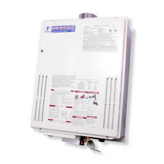
MOBIUS Water Heater
Takagi Industrial Co. USA, Inc.
Installation and Operating Instructions
MOBIUS WATER HEATER
MODEL T - M1
Instantaneous Tankless Gas Water Heater
Suitable for
Potable water heating and Space heating
Indoor and Outdoor installation
FEATURES
ENDLESS HOT WATER SUPPLY
ON-DEMAND
PILOT LESS SYSTEM
COMPACT, SAVE SPACE
COMPUTER CONTROL
COMPUTERIZED SAFTY
CONSERVES ENERGY
FULL CAPABILITY FOR MANIFOLD
Store these instructions next to the hot water heater for reference purposes.
TAKAGI INDUSTRIAL CO. USA Inc.
3-B Goodyear, Irvine, CA 92618
Tel. (949) 770-7171, FAX. (949) 770-3171
http://www.takagi-usa.com
0
Advertisement
Table of Contents

Related Manuals for Takagi T - M1


Summary of Contents for Takagi T - M1
- Page 1 MOBIUS Water Heater Takagi Industrial Co. USA, Inc. Installation and Operating Instructions MOBIUS WATER HEATER MODEL T - M1 Instantaneous Tankless Gas Water Heater Suitable for Potable water heating and Space heating Indoor and Outdoor installation FEATURES ENDLESS HOT WATER SUPPLY...
-
Page 2: Table Of Contents
• Check the rating plate to insure this product Component Diagram …………32-35 matches your specifications. Part List …………36-37 • Takagi-USA is constantly improving our Output temperature Chart …………..38 products; therefore specifications subject to change without prior notice. -
Page 3: For Your Safety
Improper installation and/or operation manual. Failure to do so will void any and all could create carbon monoxide gas and warranties offered by Takagi Industrial Co. flue gases, which could cause serious USA, Inc. injury or death. Improper installation and/or operation will void the warranty. -
Page 4: Introduction
Gas Company or installation procedures completely before doing manufacturer. the installation. If you have any problems or questions regarding this equipment, consult 6. WARNING: disconnect the Takagi Industrial Co. USA, Inc. or local electrical supply ambient factory representative. Experiences have temperatures will be reaching freezing. -
Page 5: General
Now as long as you have water, and Takagi-USA will not be held responsible gas and electricity, you will get an endless flow damage... -
Page 6: Winterizing
Winterizing If you will not be using your heater for a long period of time or if the temperatures will drop below 5º F (-15º C) with the wind chill factor, turn off your heater and drain the unit of water. This will keep your unit from freezing and being damaged. -
Page 7: Installation
INSTALLATION Accessories Check that all parts listed below were included This section is for the installer. The installer with the unit. is responsible for the correct installation of your MOBIUS Water Heater. Installation Manual, Warranty Card and For Your Safety: Optional Part Information Only certified... - Page 8 WARNING: Do not have the vent terminal pointing toward any opening into a building. Do not locate your heater in a pit or location where gas and water can accumulate. WARNING: In the USA, do not install the water heater vent terminator within 4 feet of any air intake opening into a building.
-
Page 9: Indoor Installation
If a fan blower is used to supply air to the water INDOOR INSTALLATION heater or utility room, the installer should make sure it does not create drafts, which could cause Combustion Air Supply nuisance shutdowns. If a blower is necessary to provide adequate combustion air to the water The water heater location must provide enough heater, a switch or equivalent devices must be... -
Page 10: Exhaust Vent
Follow vent pipe manufacturer’s Manufacture's recommend to use Takagi - USA instructions when installing the vent pipe. Do parts No.TK-TV01 as a vent terminator. The vent not common vent this appliance with any other terminal provides a means of installing vent pipe vented appliance. -
Page 11: Gas Supply/Piping
the unit and turning off the main gas valve during Gas Supply and Gas Piping Sizing any pressure testing of the gas supply piping system at test pressures equal to or less than ½ This unit needs a manual gas control valve Psi. -
Page 12: Water Connection
as shown in picture to prevent premature wear Water Connections of relief valve. The pressure relief valve must meet and followed local code. An approved manual water control valve (water The discharge capacity should be more than shutoff valve) must be placed on the cold water 235,000 Btu/hr. -
Page 13: Electrical Connection
Starting Operation Electrical Connections For your safety please read before start WARNING: The heater must be electrically and/or operating. grounded. Follow the requirements of the local authority having jurisdiction. In the absence of such requirements, follow the latest edition of This water heater does not have a pilot. - Page 14 flow the insure you get the right amount of hot 6.0 GPM, at a 77° F rise above the inlet water with right temperature hot water. temperature. Refer to the following chart of After the burners have ignited the “fire on” typical household flow rates to determine what lamp is lit.
-
Page 15: Wiring Diagram
Wiring Diagram A wiring diagram is located on the inside front panel of the appliance. Electrical Rating: 120 VAC, 60 Hz, 0.8 A. Note: If any of the original wiring supplied with this appliance must be replaced, it must be replaced with appliance wiring material (180c) or its equivalent. -
Page 16: For Your Safety
FOR YOUR SAFETY READ BEFORE OPERATING WARNING: If you do not follow these instructions exactly, a fire or explosion may result causing property damage, personal injury or loss of life. A. This water heater does not have a pilot. It is equipped with an electronic ignition device that automatically lights the burner. -
Page 17: Danger
DANGER Vapors from flammable liquids will explode and catch fire, causing death or severe burns. Do not use or store flammable products such as gasoline, solvents or adhesives in the same room or area near the water heater. Keep flammable products: Vapors: 1. -
Page 18: Application
Applications Space Heating Application The Mobius T-M1 can be used for space heating as well as potable heating of hot water applications. WARNING • Toxic chemicals such as used for boiler treatments chemical, alcohol, glycerol and glycol group will not be introduced into the system when used for potable water and space heating. -
Page 19: Dual-Purpose Heating
Dual-purpose hot water heating (Domestic and Space Heating) Diagrammatic Layout of Radiant Heating and Domestic Water Heater Priority Control Devices: It has a capability to make priority system that can be used as a controller flow sensor, Aquastat, or electronic controller to controlling radiant, Hydro or baseboard heating equipments. -
Page 20: Storage Tank
T-M1 with Storage Tank The maximum flow rate through the T-M1 is 9.6 GPM. If it is necessary to achieve higher flow rates for longer periods of time, then it can be installed in conjunction with a storage tank. A pump will be necessary to keep the water hot. -
Page 21: Optional Items
Optional Items 1. TM-RE10 Temperature Remote Controller 3. TK-TV03 Vent Damper TM-RE10 TK-TV03 Vent Temperature Remote Damper prevents Controller backflow of air through functions, it allows the the exhaust vent. This is output temperature CSA approved part of from the T-M1 to be unit. -
Page 22: Temperature Setting
Hot Water Output Temperature Setting: With the MOBIUS Water Heater output hot water temperature can be adjusted either with the optional remote controller (Part TM-RE10, from 95 °F to 176 °F) or manually from the main computer control boards dipswitch. Dipswitches can set four hot water output temperatures 113 °F, 140 °F, 167 °F, and 176 °F. -
Page 23: Manifold Multi System
Manifold Multi-System Application for Large Volume. MOBIUS Water Heater has full capability of manifolding multi-systems, with Multi-System Computer Control (Optional Part TM-RE20). This Multi-System Computer Controller, you can manifold from 2 units to 20 units for commercial and residential application with each computer controller. One computer (Part TM-RE20) system can make from 25,000 BTU to 4.7 Million BTU system, with fully automatic modulation for large applications. - Page 24 Multi System Main Multi System Controller (TM-RE20) and Temperature Remote Controller (TM-RE10) wiring: RE-20 RE-10 201 202 201 202 201 202 201 202 Detail Wiring: T-M1 Comunications cables are inside Box for TM-RE20. TM-RE10 Cable can be use above 18 gage wire and up to 250 ft. Wire No.
- Page 25 Pump Connection: MOBIUS Water Heater Main Multi System Controller will be maintaining set water temperature inside storage tank automatically with T-M1 ON/OFF Mode. Circulation Pump between T-M1 system and Storage has to be ON (running) 24-Hour, it will maintain set temperature. Pull out jump cable for Store for activates power port.
- Page 26 LP or Natural Gas, Please don’t change these switch, Factory already set it correctly. When unit is firing, this RED LED will be ON For Single or Multi mode JUMP cable. For Multi mode, permanently pull out. Error signal LED, this LED shows for unit error, also it will show on RE-10 and RE20.
-
Page 27: Maintenance And Service
Maintenance and Service warranty and shorten the life of your water heater. WARNING: Turn off the electrical power Common Trouble Shooting supply, the manual gas control valve, and the manual water control valve before Water Isn’t Hot Enough servicing. The T-M1 can burn gas at a maximum Do this immediately after installation. -
Page 28: Error Codes
GFCI and the circuit plate. Contact Takagi Industrial Company for Instructions. Error Codes All Takagi units are self diagnostic for errors. If there is a problem with the installation or the TK-RE10 unit, it will give a signal, through a pair of... -
Page 33: Component Diagram
MOBIUS Water Heater Parts List and Component Diagram 37 38... - Page 35 1 0 4...
-
Page 37: Part List
Parts List Part No. Description Part No. Description Case Assembly Screw M4 x 12 Brackets Flange Screw (W) M4 x 10 Flow Adjustment Valve Back Guard Panel O-ring P16 Transformer Bypass Junction Transformer Screw M4 x 6 Junction Box O-ring P18 Junction Box Cover Water Outlet Connection Screw M4 x 8... - Page 38 Burner Assembly Igniter Screw M4- 12 Screw M4 x 6 Wire Holder Solenoid Valve Wire Spark Electrode Holder Packing Proportional Valve Wire Spark Electrode Holder Gas Valve Unit Screw M4 x 10 O-ring P22 Silicon Cap O-ring P18 Spark Electrode Fixing Plate Screw M4 x 8 High Voltage Igniter Cable O-ring P26...
Need help?
Do you have a question about the T - M1 and is the answer not in the manual?
Questions and answers