Table of Contents
Advertisement
Quick Links
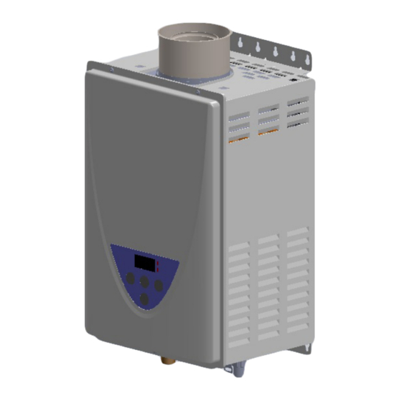
On-Demand Water Heater
Installation Manual and Owner's Guide
ANSI Z21.10.3 ・ CSA 4.3
Gas Tankless Water Heater
Suitable for combination potable water heating
and space-heating.
Please refer to local codes
for space-heating compliance.
FEATURING
• ENDLESS HOT WATER
• ON-DEMAND USAGE
• COMPACT, SPACE SAVING
• ENERGY CONSERVATION
• COMPUTERIZED SAFETY
• ELECTRONIC IGNITION
• Complies with SCAQMD Rule
1146.2 for natural gas Low NOx
Emissions of 14 ng/J or 20-ppm
• CONCENTRIC VENT
• FIELD GAS CONVERSION
• EASY-LINK SYSTEM*
• MULTI-UNIT SYSTEM*
*(510C model only)
Keep this manual near the water heater for future reference whenever maintenance, adjustment, or
service is required.
R
D
R
TM
510C
model only
If the information in these
instructions is not followed
exactly, a fire or explosion may
result causing property damage,
WARNING
personal injury or death.
- Do not store or use gasoline or other
flammable vapors and liquids in the vicinity
of this or any other appliance.
- WHAT TO DO IF YOU SMELL GAS
• Do not try to light any appliance.
• Do not touch any electric switch, do not
use any phone in your building.
• Immediately call your gas supplier from
a neighbor's phone. Follow the gas
supplier's instructions.
• If you cannot reach your gas supplier, call
the fire department.
- Installation and service must be performed
by a qualified installer, service agency or the
gas supplier.
If you have any questions, please
call or write to:
In the United States
500 Tennessee Waltz Parkway
Ashland City, TN 37015
Toll Free: 1-877-737-2840
In Canada
599 Hill Street West
Fergus, ON N1M 2X1
1-888-479-8324
Models
• 110C
• 310C
• 510C
Advertisement
Table of Contents

Subscribe to Our Youtube Channel
Related Manuals for Takagi 110c


Summary of Contents for Takagi 110c
- Page 1 On-Demand Water Heater Installation Manual and Owner’s Guide Models • 110C • 310C 510C ANSI Z21.10.3 ・ CSA 4.3 • 510C model only If the information in these instructions is not followed exactly, a fire or explosion may result causing property damage, WARNING personal injury or death.
-
Page 2: Table Of Contents
Contents CONTENTS Installation Manual Owner's Guide SPECIFICATIONS ..........4 OPERATING SAFETY ........31 INTRODUCTION..........5 NORMAL OPERATION ........33 SAFETY GUIDELINES........6 BUILT-IN CONTROLLER SAFETY DEFINITION ........6 AND REMOTE CONTROLLER ....33 GENERAL ............6 GENERAL ............33 INSTALLATION ..........7 TEMPERATURE SETTING ......34 GENERAL ............7 Set temperature ........34 CLEARANCES ..........9 TEMPERATURE TABLE OF CONTROLLER .34 INCLUDED ACCESSORIES ......9... -
Page 3: Installation Manual
Installation Manual Installation Manual CONGRATULATIONS Congratulations and thank you for choosing our tankless water heater. Before use, we recommend that you read through this installation manual carefully. Keep this manual for future reference. If you need an additional manual, contact the manufacturer or your local distributor. -
Page 4: Specifications
Installation Manual Specifications SPECIFICATIONS Model 110C 310C 510C Natural Gas Input Min.: 15,000 Min.: 15,000 Min.: 15,000 BTU/h (Operating Range) Max.: 140,000 Max.: 190,000 Max.: 199,000 Gas Connection 3/4" NPT Water Connections 3/4" NPT Water Pressure* 15 - 150 (0.1 - 1) -
Page 5: Introduction
• This appliance is an on-demand, tankless water heater. It is designed to efficiently supply endless hot water for your needs. • The 110C, 310C, and 510C models are only to be installed indoors with concentric venting. • The principle behind tankless water heaters is simple:... -
Page 6: Safety Guidelines
Installation Manual Safety Guidelines SAFETY GUIDELINES SAFETY DEFINITION Indicates an imminently hazardous situation which, if not avoided, will result in death or serious injury. DANGER Indicates an imminently hazardous situation which, if not avoided, could result in death or seri- ous injury. -
Page 7: Installation
8. 110C, 310C, and 510C models: A condensate collector and trap (100266140 & 100266139) are required to be installed in the venting system when there is more than 8 ft (2.4 m) of equivalent vent length, not including the sidewall termination. - Page 8 Installation Manual Installation • Installation and service must be performed by a qualified installer (for example, a licensed plumber or gas fitter). Otherwise, the warranty will be void. • The installer (licensed professional) is responsible for the correct installation of the water heater and for compliance with all national, state/provincial, and local codes.
-
Page 9: Clearances
Front hazard, potentially leading to death, serious Side injury, and/or property damage. WARNING Model Bottom Front Back Sides Bottom 110C 12 in. 12 in. 4 in.* 1 in. 3 in. 310C (305 mm) (305 mm) (102 mm) (25 mm) (76 mm) 510C *24 inches (610 mm) recommended for maintenance. - Page 10 Installation Manual Installation 2. Concentric Sidewall Termination Kit 1. Condensate Collector and Trap 11 1/2" (292mm) (100266115) 21" (533 mm) (100266117) Trap Collector It includes: One Sidewall Termination, One 87° Elbow, (100266139) (100266140) Two Wall Plates. 3. Concentric Roof Termination 4.
-
Page 11: Warning For Installations
Installation Manual Installation WARNING FOR INSTALLATIONS FOR YOUR SAFETY, READ BEFORE INSTALLATION: • Do not install the water heater and its termination where water, debris or flammable vapors may get into the water heater and flue terminal. • Do not have the vent terminal pointing toward any opening into a building. •... -
Page 12: High-Altitude Installations
The black squares indicate the correct DIP switch positions for high altitude installation. The 110C and 310C : Only adjust DIP switch No. 3, No. 4, and No.5. The 510C : Only adjust DIP switch No. 2, No. 3, and No. 4 on the lower bank. -
Page 13: Venting Instructions
Installation Manual Installation VENTING INSTRUCTIONS -General- • Improper venting of this appliance can result in excessive levels of carbon monoxide which can result in severe personal injury or death. • Improper installation can cause nausea or asphyxiation, severe injury or death from carbon monoxide and flue gases poisoning. -
Page 14: Vent Length And No. Of Elbows
• Failure to observe these warnings could lead to carbon monoxide poisoning or death. 510C Computer board Upper bank of 110C and 310C: DIP switches Only adjust DIP switch No. 6 , No. 7, and No. 8. 510C: Only adjust DIP switch No. 3, No. 4, and No. 5 on the upper bank. -
Page 15: Venting Illustrations
Installation Manual Installation -Venting illustrations- For the 110C, 310C and 510C models For details of the venting installation, refer to the Centrotherm Eco Systems Direct Vent APNC35 concentric venting installation manuals. Horizontal Installation Standard Sidewall kit 11.5" (292 mm):100266115 21" (533 mm):100266117 Straight Pipe 10"... -
Page 16: Vent Termination Clearances
Installation Manual Installation -Vent termination clearances- Inside corner = Vent terminal detail = Air supply inlet = Area where the terminal is not permitted Fixed Operable Fixed closed closed Operable Regulator/Gas meter vent outlet Canada Installations US Installations Direct-vent Direct- vent Clearance above grade, veranda, porch, deck, or balcony 1 ft (30 cm) 1 ft (30 cm) -
Page 17: Clearances For Sidewall Terminations
Installation Manual Installation Improper installation can result in carbon monoxide poisoning or death. Follow all local and national codes in regards to proper termination clearances. In the absence of such codes, the clearances below can be used as guidelines. Local codes supersede these WARNING guidelines. -
Page 18: Gas Supply And Gas Pipe Sizing
Installation Manual Installation GAS SUPPLY AND GAS PIPE SIZING -General- • Do not use this water heater with any gas other than the one listed on the rating plate unless the water heater has been properly converted. • Ensure that any and all gas regulators used are operating properly and providing gas pressures within the specified range shown below. -
Page 19: Natural Gas Supply Piping
Maximum delivery Capacity of Cubic Feet of Gas per Hour of IPS Pipe carrying Natural Gas with 0.60 Specific Gravity Based on Pressure Drop of 0.5" W.C. Based on Energy Content of 1,000 BTU/Cubic ft: The water heater requires 140 Cubic ft/hr for the 110C, 190 Cubic ft/hr for 310C, and 199 Cubic ft/hr for the 510C model. -
Page 20: Water Connections
• The pressure relief valve must conform to the current edition of ANSI Z21.22 or CAN 1-4.4 and instal- lation must follow local codes. • The discharge capacity must be at least 140,000 BTU/h for the 110C model, 190,000 BTU/h for the 310C model, and 199,000 BTU/h for the 510C model. -
Page 21: Electrical Connections
Installation Manual Installation ELECTRICAL CONNECTIONS • Follow the electrical code requirements of the local authority having jurisdiction. In the absence of such requirements, follow the current edition of the National Electrical Code ANSI/NFPA 70 in the U.S. or the current edition of CSA C22.1 Canadian Electrical Code Part 1 in Canada. -
Page 22: Temperature Remote Controller
Installation Manual Installation TEMPERATURE REMOTE CONTROLLER -Optional item- • The remote control is an optional accessory that can be installed in a hall, closet, etc., to allow for temperature adjustment without having to go to the heater. • When installed, the remote will take priority over the built-in controller. Verify that the items listed below are included with the remote controller 100209924 (TM-RE42). - Page 23 * Do NOT jump or short-circuit the wires, or the computer will be damaged. 6. Replace the water heater's front cover securely. Fig. E-1 Fig. E-2 100209924 100209924 110C and 510C model (TM-RE42) (TM-RE42) 310C models Connect other end to these terminals...
-
Page 24: Easy-Link System
Installation Manual Installation EASY-LINK SYSTEM (Available on the 510C model only) -General- The 510C model water heaters can be connected together to work as a multiple-unit manifold system. • The built-in Easy-Link System allows up to 4 units to manifold together (connected with com- Gas In munication cables). - Page 25 Installation Manual Installation When the built-in controller installed in the “CHILD-2” unit displays a number, turn on “CHILD-3”. Make sure the built-in controller installed in each child unit displays each unit #. (Refer to p.40.) The numbering system automatically allocates the unit No. to each water heater in the Easy-Link System, in accordance with the table below.
-
Page 26: Multi-Unit System
Installation Manual Installation MULTI-UNIT SYSTEM Multiple 510C models can be combined for a Multi-Unit System, along with the multi-unit controller (Part 100112691 (TM-MC02)). Each multi-unit/remote controller set can control from 2 to 20 units for commercial or residential applications. For a 20-unit system, the computer can modulate between the usages of 15,000 BTU/h to 3.98 million BTU/h. -
Page 27: Applications
Installation Manual Applications APPLICATIONS -Space-Heating Applications- • This water heater is suitable for combination water (potable) heating and space heating and not suitable for space heating applications only. • In order to purge air in water pipes within a closed-loop system, an air vent and air separator should be installed in the system. -
Page 28: Dual-Purpose Hot Water Heating
Installation Manual Installation -Dual-purpose hot water heating- (Domestic and Space Heating): Diagrammatic layout of radiant heating and domestic water heater. All water piping should be insulated in accordance with 780 CMR (Massachusetts energy code) 3/5 inch concentric vent (Discharge must Cold water supply Automatic tempering device comply with local and... -
Page 29: Initial Operation
Installation Manual Initial operation INITIAL OPERATION FOR YOUR SAFETY, READ BEFORE OPERATING • Check the GAS and WATER CONNECTIONS for leaks before firing unit for the first time. • Open the main gas supply valve to the unit using only your hand to avoid any spark. Never use tools. -
Page 30: Owner's Guide
Owner's Guide Owner's Guide CONGRATULATIONS Congratulations and thank you for choosing our tankless water heater. Before use, we recommend that you read through this owner's guide carefully. Keep this manual for future reference. If you manual, contact the manufacturer or your need an additional local distributor. -
Page 31: Operating Safety
Owner's Guide Operating Safety OPERATING SAFETY FOR YOUR SAFETY READ BEFORE OPERATING WARNING: If you do not follow these instructions exactly, a fire or explosion may result causing property damage, personal injury or loss of life. A. This appliance does not have a pilot. It is equipped with an ignition device which automatically lights the burner. - Page 32 Owner's Guide Operating Safety DANGER Vapors from flammable liquids will explode and catch fire causing death or severe burns. Do not use or store flammable products such as gasoline, solvents or adhesives in the same room or area near the water heater. Flammable Vapors FLAMMABLES Read and follow water heater warnings and instructions.
-
Page 33: Normal Operation
Owner's Guide Normal Operation NORMAL OPERATION BUILT-IN CONTROLLER and REMOTE CONTROLLER The illustrations below show examples of the displays of the controller. The exact display may differ from examples. Remote controller Built-in controller Display for Temperature "INFO" Button When the STAND BY LED is ON, the hot water temperature will be Each time the button is pressed, displayed. -
Page 34: Temperature Setting
145 °F (63 °C). 4. Press the "HOT" button to set up to 160 °F (70 °C). TEMPERATURE TABLE OF CONTROLLER a) For 110C and 310C models °F 100 105 110 115 120* 125 130 135 140 °C... -
Page 35: Additional Features
Owner's Guide Normal Operation ADDITIONAL FEATURES -Information mode- You can get some information about the water heater condition by pressing the "INFO" button. For more information, follow the procedures below: Screen on the controller INFO Operation Button Built-in controller Remote controller Inlet water temperature will be displayed on 1st. -
Page 36: Temperature Settings On The Pcb
NOTE: The black square indicates the correct DIP switch position for set temperature. For the 110C and 310C, only adjust DIP switch No. 9. For the 510C, only adjust DIP switch No. 5 on the lower bank. Do not adjust the other DIP switches for temperature adjustment. -
Page 37: Freeze Protection System
Owner's Guide Normal Operation FREEZE PROTECTION SYSTEM • This unit comes equipped with heating blocks to protect it from damage associated with freezing. • For this freeze protection system to operate, there has to be electrical power to the unit. Damage to the heat exchanger caused by freezing temperatures due to power loss is not covered under the warranty. -
Page 38: Measuring Inlet Gas Pressure
Press the MIN button on the computer board. (Refer to the diagrams below.) Take a supply gas pressure reading and verify that it is within the specified inlet gas pressure range. 110C and 310C Computer board 510C Computer board... -
Page 39: Troubleshooting
Owner's Guide Troubleshooting TROUBLESHOOTING GENERAL PROBLEM SOLUTIONS It takes a long time to • The time it takes to deliver hot water from the water heater to your get hot water at the fixtures depends on the length of piping between the two. The longer fixtures. - Page 40 Owner's Guide Troubleshooting PROBLEM SOLUTIONS Unit does not ignite • Is the flow rate over 0.5 GPM (1.9 L/min)? (p. 33) when water goes • Check the filter on cold water inlet. (p. 38) through the unit. • Check for reverse connection and cross connection. •...
-
Page 41: Error Codes
• If there is a problem with the installation or the unit, the error code will be displayed on the temperature controller and remote controller. • Consult the table on the following pages for the description of each error code. 110C and 310C 510C model Error code indicator on... -
Page 42: Fault Analysis Of Error Codes
709), burn marks on the computer board (Part #701), and/or soot on the flame rod (Part #108). • Check if there is leaking from heat exchanger (Part #401). 311* Two Flashes 110C & 310C: Outlet thermistor failure 510C: Heat exchanger •... - Page 43 Owner's Guide Troubleshooting Malfunction Remote Green LED Diagnosis description Four Flashes Flow adjustment • Inspect the flow adjustment valve (Part #402), for valve fault (Only connection/breakage of wires, locked motor drive due to Easy-Link & Multi-Unit scale buildup, and/or water leakage. System) 661* Four Flashes...
-
Page 44: Components Diagram
Owner's Guide Components Diagram COMPONENTS DIAGRAM Case assembly Built-in temperature controller Page... - Page 45 Owner's Guide Components Diagram Computer board assembly 110C and 510C model 310C models Surge box assembly Page...
- Page 46 Owner's Guide Components Diagram Burner assembly LP Conversion Kit 707 702 510C model Gas conversion sticker Page...
- Page 47 Owner's Guide Components Diagram Water Way assembly 110C & 310C model Bypass section (510C model) To Water inlet section To Water outlet section 459 454 To Water 510C model inlet section To Water outlet section Water inlet section Water outlet section...
-
Page 48: Parts List
100281154 EK591 Manifold Gasket 100281157 EK592 O-ring (Manifold) EK570 O-ring P20 NBR (Black) 100074242 EK042 Heat exchanger assembly for 110C, 310C 100224107 EK571 for 510C 100224108 EK572 Flow adjustment valve / Flow sensor 100074624 EK129 Bypass valve for 510C model... - Page 49 Surge box 100076100 EK280 120 VAC wire 100074601 EK146 Switch wire EK584 120 VAC Power ON-OFF switch EK590 Remote controller wire for 110C and 310C models 100074649 EK189 for 510C model 100074650 EK165 Gas valve wire EK585 Flame rod wire EK586...
-
Page 50: Output Temperature Chart
Owner's Guide Output Temperature Chart OUTPUT TEMPERATURE CHART Chart is based on properly sized gas line Output Temperature vs. GPM (Max. 6.6 GPM) with Various Inlet Water Temperature 110C ( L /M) 40°F(4°C) 50°F(10°C) 60°F(16°C) 70°F(21°C) °F(°C) Set Temp. (38) - Page 51 This page is intentionally left blank. Page...
- Page 52 1W5101-4 DIR 2000535218 (REV. B)
Need help?
Do you have a question about the 110c and is the answer not in the manual?
Questions and answers