Table of Contents
Advertisement
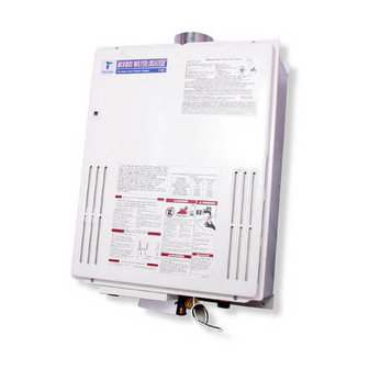
MOBIUS Water Heater
Store these instructions next to the hot water heater for reference purposes.
Potable water heating and Space heating
FEATURES
ENDLESS HOT WATER SUPPLY
θ
ON-DEMAND
θ
θ
PILOT LESS SYSTEM
COMPACT, SAVE SPACE
θ
COMPUTER CONTROL
θ
COMPUTERIZED SAFTY
θ
CONSERVES ENERGY
θ
FULL CAPABILITY FOR MANIFOLD
θ
Takagi Industrial Co. USA, Inc.
Installation and Operating Instructions
MOBIUS WATER HEATER
MODEL T - M1
Instantaneous Tankless Gas Water Heater
Suitable for
Indoor and Outdoor installation
TAKAGI INDUSTRIAL CO. USA Inc.
6 Goddard, Irvine, CA 92618
Tel. (949) 453 - 8388, FAX. (949) 453-8498
http://www.takagi-usa.com
Advertisement
Table of Contents

Related Manuals for Takagi Mobius T - M1


Summary of Contents for Takagi Mobius T - M1
- Page 1 MOBIUS Water Heater Takagi Industrial Co. USA, Inc. Installation and Operating Instructions MOBIUS WATER HEATER MODEL T - M1 Instantaneous Tankless Gas Water Heater Suitable for Potable water heating and Space heating Indoor and Outdoor installation FEATURES ENDLESS HOT WATER SUPPLY θ...
- Page 2 Takagi Tankless Gas water heather. Do not copy this installation manual without consent from Takagi Industrial Co. USA Inc. Copy Right 2002, Takagi Industrial Co. USA Inc. FOR YOUR SAFETY - This product must...
-
Page 3: Table Of Contents
CONTENTS SPECIFICATIONS For Your Safety …………. 4 Natural Gas Input Min. 25,000 Btu Max. 235,000 Btu Operation …………. 5 LPG Input Min. 25,000 Btu • Max. 225,000 Btu General …………. 5 • Temperature …………. 5 • Gas Connection ¾” NPT Freeze Prevent Device …………. -
Page 4: For Your Safety
If you have any problems or for more information. Warranty will not be questions regarding this equipment, consult covered if the heat exchanger is damaged the Takagi Industrial Co. USA, Inc. or local by weather. Please read winterize section factory representative. -
Page 5: Operation
gas and electricity, you will get an endless flow of hot water. Open a hot water tap to turn on your water heater. Close the tap to turn off your water heater. Temperature The temperature has been set at the factory Max. -
Page 6: Freeze Prevent Device
the exhaust venting when the water heater is Freeze Prevention Devices on standby which can damage the heat exchanger. This unit comes equipped with heater blocks to CAUTION: The pipe heaters are located on prevent freezing which can damage the heat exchanger. -
Page 7: Installation
4. Open all hot water taps in the house. (Bathroom, kitchen, laundry room, etc.). INSTALLATION When the water flow has ceased, close all hot water taps. 5. Have a bucket or pan to catch the water This section is for the installer. The installer from the units drain plugs. -
Page 8: Accessories
thimble. Install vent terminator in accordance with manufacturer’s installation instructions Accessories and any applicable local codes. 3. TK-TV03 Vent Damper Check that all parts listed below were included with the unit. Installation Manual, Warranty Card and Optional Part Information The TK-TV03 Vent Damper prevents the backflow of air through the exhaust vent. -
Page 9: Indoor Installation
WARNING: In the USA, do not install the water Do not install this water heater under an heater vent terminator within 4 feet of any air overhang, less than 3 feet from its top or eaves. intake opening into a building. In Canada do The area under an overhang must be open to not install the water heater vent terminator three sides... -
Page 10: Venting Instructions
Air Supply from Outside Building Monoxide, which can result in severe personal injury or death. When combustion air supplied directly through This water heater must vented an outside wall, such as intake louvers accordance with "Section Venting openings into the dwelling, opening should Equipment", of the latest edition of the National give a minimum free area of one square inch Fuel... - Page 11 other approved, noncombustible, corrosion- Indoor installation clearance. resistant material. The following are UL listed Piping side (Bottom of water Min. 12” manufacturers: ProTech Systems, FasNSeal, Z-Flex Inc. Z-Vent II and Heat-Fab Inc. Saf-T heater) Vent. This unit requires 4” vent pipe. Connect Front (Maintenance space) Max.
-
Page 12: Gas Supply
Installation vent terminator Clearance Gas Supply and Gas Piping Sizing heater’s performance to diminish and unable to reach maximum performance. When connections are completed, check for This unit needs a manual gas control valve gas leaks by applying soapy water to all gas (System Shutoff Valve) that must be placed on fittings and connections. -
Page 13: Water Connection
NOTE: These Tables are for Natural Gas (0.60 Recommend Gas pipe size for Specific Gravity) and based on Pressure Drop MOBIUS Water Heater of 0.5 Inch water columns. This table is Gas Distance from Gas Meter Pipe Size (inches) piping supply straight to the water heater 0' - 20' 3/4"... -
Page 14: Pressure Relief Valve
the water supplier or local plumbing inspector on how to correct this situation. The pressure relief valve must be manually operated once a year to check for correct operation. Should overheating occur or gas supply fail to shut off, turn off the manual gas control valve to the appliance. -
Page 15: Starting Operation
• A means for switching on/off the 120 VAC power supply must be provided for service WHAT TO DO IF YOU SMELL THE GAS! reasons. • Wire the heater exactly as shown in the wiring diagram. 1. Do not try to start the water heater. •... - Page 16 air to the heater. Purge the gas and water lines to remove Air pocket. Then follow these steps to turn on your unit. 1. Close the manual gas control valve located To Turn off your Mobius water heater on the gas line. 1.
-
Page 17: Wiring Diagram
Wiring Diagram A wiring diagram is located on the inside front panel of the appliance. Electrical Rating: 120 VAC, 60 Hz, 0.8 A. Note: If any of the original wiring supplied with this appliance must be replaced, it must be replaced with appliance wiring material (180c) or its equivalent. -
Page 18: For Your Safety
FOR YOUR SAFETY READ BEFORE OPERATING WARNING: If you do not follow these instructions exactly, a fire or explosion may result causing property damage, personal injury or loss of life. A. This water heater does not have a pilot. It is equipped with an electronic ignition device that automatically lights the burner. - Page 19 DANGER Vapors from flammable liquids will explode and catch fire, causing death or severe burns. Do not use or store flammable products such as gasoline, solvents or adhesives in the same room or area near the water heater. Keep flammable products: Vapors: 1.
-
Page 20: Application
Applications Space Heating Application The FLASH T-K2 can be used for space heating as well as potable heating of hot water applications. WARNING • Toxic chemicals such as used for boiler treatments chemical, alcohol, glycerol and glycol group will not be introduced into the system when used for potable water and space heating. •... -
Page 21: Dual-Purpose Heating
Dual-purpose hot water heating (Domestic and Heating): Pressure Relief Valve Air Vent Pump Radiant, Hydro or Baseboard Expansion Tank Heating Equipment. Domestic Priority Control Devices potable water Check Valve Cold water supply Priority Control Devices: It has a capability to make priority system that can be used as a controller flow sensor, Aquastat, or electronic controller to controlling radiant, Hydro or baseboard heating equipments. -
Page 22: Storage Tank
T-M1 with Storage Tank Hot Out Cold In Relief Valve Check valve Hot Water Recirculation Recirc. Pump Pump The maximum flow rate through the T-M1 is 9.6 GPM. If it is necessary to achieve higher flow rates for longer periods of time, then it can be installed in conjunction with a storage tank. A pump will be necessary to keep the water hot. -
Page 23: Temperature Setting
Hot Water Output Temperature Setting: With the MOBIUS Water Heater output hot water temperature can be adjusted either with the optional remote controller (Part TM-RE10, from 95 ° F to 176 ° F) or manually from the main computer control boards dipswitch. - Page 24 Multi System Main Multi System Controller (TM-RE20) and Temperature Remote Controller (TM-RE10) wiring: RE-20 RE-10 201 202 201 202 201 202 201 202 Detail Wiring: T-M1 Comunications cables are inside Box for TM-RE20. TM-RE10 Cable can be use above 18 gage wire and up to 250 ft. Wire No.
- Page 25 Pump Connection: MOBIUS Water Heater Main Multi System Controller will be maintaining setting temperature inside storage tank water with automatically T-M1 ON/OFF Mode. Circulation Pump between T-M1 system and Storage has to be ON (running) 24- Hour, it will maintain set temperature.
- Page 26 Firing System: Power on each T-M1 and TM-RE20, then TM-RE10 will show Number 0000 for 20 to 25 second. Next, the RE-10 will show a default temperature setting of 108F this can be changed with HOT and COLD button located on the TM-RE10. If you press the ON/OFF button this time, RE10 shows current TIME that can be changed, refer to the instructions provided with the TM-RE10.
-
Page 27: Maintenance And Service
solution. Scale build up will void your Maintenance and Service warranty and shorten the life of your water heater. WARNING: Turn off the electrical power supply, the manual gas control valve, and Common Trouble Shooting the manual water control valve before servicing. -
Page 28: Error Codes
If this light is not lit, there is a problem with the electrical connection between the GFCI and the circuit plate. Contact Takagi Industrial Company for Instructions. Error Codes TK-RE10 All Takagi units are self diagnostic for errors. -
Page 29: Trouble Shooting
Start Power On Valve A failure Maintenance Circuit board for valve D.E.F Failure All display off ‡ @ Open Valve A ‡ D ‡ A Open Valve B High-limit switch off Power off ‡ P Open Valve C Open Short: ‡... - Page 30 Stop Faucet close ‡ H Valve A Open limit On (After 18 sec.) Flow sensor off Fan motor rotation Valve H Off (<1000rpm) (After 20 sec.) Fan Off Valve E Off ‡ I Fan motor On Valve F Off ‡ J Fan motor rotation Pass 5 sec.
- Page 31 (After 60 sec.) Output temp down Check power =< Min. BTU Check power =< Mid. BTU Valve E Off Valve F Off Valve E On Valve E On Valve F Off Valve F On Capacity check =< Max. BTU Thermocouple =>...
- Page 32 Hi-limit switch works (=>208F) Circuit board for Valve D failure Abnormal high water temperature Open Short: ‡ E Inlet Temp. Thermistor Open Short: Output Temp. Thermistor Open Short: Display: running off Mixing Temp. Thermistor Thermo fuse cut off Flame detector (=>360F) <Wter Valve>...
-
Page 33: Component Diagram
MOBIUS Water Heater Parts List and Component Diagram 37 38... - Page 35 1 0 4...
-
Page 37: Part List
Parts List Part No. Description Part No. Description Case Assembly O-ring P25 Brackets Filter Screw (W) M4 x 10 Packing Back Guard Panel Combustion Chamber Transformer Burner Assembly Transformer Screw M4 x 12 Junction Box Wire Holder Junction Box Cover Spark Electrode Holder Packing Screw M4 x 8 Spark Electrode Holder... - Page 38 Flange Screw M4 x 6 Flow Adjustment Valve Solenoid Valve Wire O-ring P16 Proportional Valve Wire Bypass Junction Gas Valve Unit Screw M4 x 6 O-ring P22 O-ring P18 O-ring P18 Water outlet Connection Screw M4 x 8 Screw M4 x 14 O-ring P26 Mixing Thermistor Gas Inlet...
-
Page 39: Output Temperature Chart
Out Put Temperature vs. GPM (Max. 9.6 GPM) with Various Ground Water Temperature Correct Gas pipe size can be expect this chart 12.0 10.0 40 F 50 F 60 F 70 F Out put Hot Water Temperature 40 F 50 F 60 F 70 F...
Need help?
Do you have a question about the Mobius T - M1 and is the answer not in the manual?
Questions and answers