
Related Manuals for Advantech PPC-412


Summary of Contents for Advantech PPC-412
- Page 1 User Manual PPC-412 ® Intel Core i Processor Based Microcomputer, with 12.1" Color TFT LCD Display...
- Page 2 No part of this manual may be reproduced, copied, translated, or transmitted in any form or by any means without the prior written permission of Advantech Co., Ltd. The information provided in this manual is intended to be accurate and reliable.
- Page 3 This product has passed the CE test for environmental specifications when shielded cables are used for external wiring. We recommend the use of shielded cables. This type of cable is available from Advantech. Please contact your local supplier for ordering information.
- Page 4 Liquid has penetrated the equipment.Le liquide a pénétré dans l'appareil. – The equipment has been exposed to moisture.L'appareil a été exposé à l'humidité. – The equipment is malfunctioning or does not function according to the user manual.L'appareil est défectueux ou ne fonctionne pas conformément aux instructions. PPC-412 User Manual...
- Page 5 704-1:1982, le niveau de pression acoustique à la position de l'opérateur ne dépasse pas 70 dB (A). The product PPC-412 are intended to be supplied by an UL certified power sup- ply (Adapter: FSP090-DIEBN2) suitable for use at Tma 40 degree C min. and output is rated 19Vdc, 4.74A min., ES1 (or SELV) or the product are intended to...
- Page 6 Battery Information Batteries, battery packs and accumulators should not be disposed of as unsorted household waste. Please use the public collection system to return, recycle, or treat them in compliance with the local regulations. PPC-412 User Manual...
-
Page 7: Table Of Contents
Front Panel....................2 Figure 1.1 Front Panel ..............2 Rear Panel ....................3 Figure 1.2 Rear Panel_PPC-412 ..........3 Dimensions ....................3 Figure 1.3 PPC-412 Dimensions ..........3 Specifications ................... 4 Ordering Information ................. 5 Chapter System Installation & Setup ....7... - Page 8 Entering BIOS Setup ..............32 4.2.2 Adjustment of LCD Brightness............ 33 4.2.3 COM3 Mode Selection (RS422/RS485) ........35 4.2.4 BIOS AT & ATX Setup..............38 4.2.5 Wake on LAN or Ring ..............39 4.2.6 TPM Settings ................40 PPC-412 User Manual viii...
-
Page 9: Chapter 1 General Information
Chapter General Information This chapter gives background information on the PPC-412 panel Sections include: Introduction Specifications Dimensions... -
Page 10: Introduction
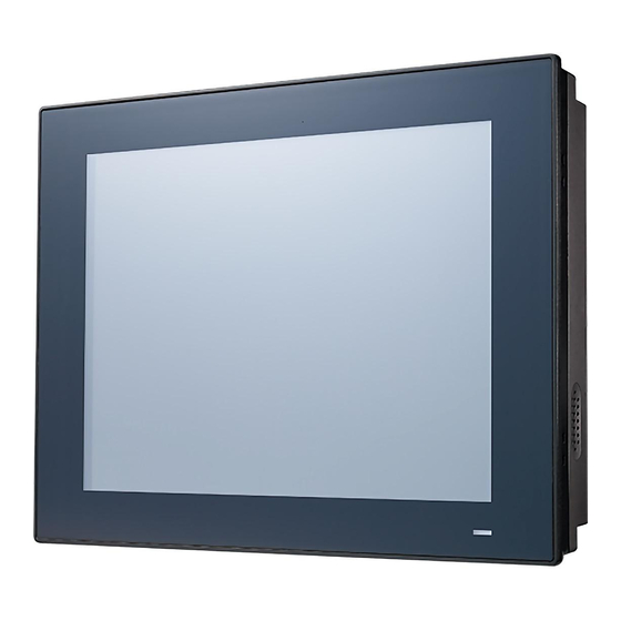
Introduction The PPC-412 is a new generation Panel PC with XGA (1024 x 768) screen. The sys- tem is equipped with a high performance Intel Core i CPU and with a high efficiency fanless thermal design in which the heat is easily dissipated. It has multiple I/O ports (five COM, five USB and two Gigabit ethernet) making more applications possible. -
Page 11: Rear Panel
Rear Panel The PPC-412 rear panel features four VESA mount holes (75 x 75 mm), as shown in Figure 1.2. Figure 1.2 Rear Panel_PPC-412 Dimensions 317.00 Cut-out dimension:311mm x 240mm Figure 1.3 PPC-412 Dimensions Supports VESA 75 x 75mm. Use M4 screws, 8 mm depth Note! (maximum). -
Page 12: Specifications
Operating random vibration test, 5 ~ 500Hz, 2Grms with SSD, Vibration following IEC 60068-2-64 Safety: CB, UL, CCC, BSMI Safety and EMC EMC: CE, FCC Class B, BSMI Dimensions 317 x 246 x 60.5 mm (12.4 x 9.7 x 2.4 in) Weight 3.4 kg (7.5 lb) PPC-412 User Manual... -
Page 13: Ordering Information
Intel Core i5-7300U Fanless PPC PPC-412 with 12.1" XGA LED backlight, resistive touch Power adapter 100 ~ 240 V 96PSA-A90W19OT-3 90 W, 19V with PFC PPC-WLAN-C1E Wi-Fi module with antenna PPC-ARM-A03 Arm mount VESA standard PPC-174T-WL-MTE Wall mount kit PPC-412 User Manual... - Page 14 PPC-Stand-A1E Stand kit 98R3P321110 TPM 2.0 module PPC-412 User Manual...
-
Page 15: Chapter 2 System Installation & Setup
Chapter System Installation & Setup Sections include: Quick Installation Guide Installation Procedures Installing Memory Installing HDD Installing M.2 Installing Wireless LAN Installing Side COM Port/GPIO Installing TPM Installing Expansion Card AT/ATX Function Switch ... -
Page 16: Quick Start Guide
When you place the panel PC upright on the desktop, its front panel appears as shown in Figure 2.1. Figure 2.1 Front Panel Power status indicator, off (S5): orange, on (S0): blue. Figure 2.2 Side View Antenna hole (two) Panel mount bracket holes (eight) CPU heatsink Speaker (two) PPC-412 User Manual... - Page 17 D. 1 x Display port E. 2 x RS-232 F. 1 x Isolated RS-422/485 G. SYS ground H. 4 x USB3.0 I. 1 x VGA J. 1 x DC Input and AT/ATX switch K: 1 x Power button PPC-412 User Manual...
-
Page 18: Installation Procedures
Please follow the procedures below: Connect the female end of the power cable to panel PC’s DC socket. Connect the male end of the power cable to power outlet. Figure 2.4 Connecting the Power Cable PPC-412 User Manual... -
Page 19: Connecting The Keyboard And Mouse
Loosen the screws as indicated in the red circle. (See Figure 2.5). Press the red areas to pull out the hook (See Fig 2.6 ~ 2.7) and open the rear cover. Figure 2.5 Figure 2.6 Figure 2.7 PPC-412 User Manual... - Page 20 Figure 2.9). Attach the CPU heat sink and strength plate after the grease is applied. Figure 2.9 Figure 2.8 Note! CPU cooler pad surface is isolated by anodization treatment to avoid static electricity (CPU contact side excluded). PPC-412 User Manual...
-
Page 21: Installing The Ssd
Installing the SSD Follow the procedures in Section 2.3 to open the rear cover and remove the screws as indicated in the red circles in Figure 2.10. Figure 2.10 PPC-412 User Manual... - Page 22 Install the SSD (see Figure 2.11), and take out the 4 screws from the accessory box to attach the SSD and then attach the strength-plate. Figure 2.11 Lock the HDD bracket, and connect the HDD cable to the mainboard (see Fig- ure 2.12). Figure 2.12 PPC-412 User Manual...
-
Page 23: Installing M.2
(See Figure 2.13). Plug the M.2 into the mainboard interface, and remove the 2 M2.5x4 screws from the accessory box to attach (see Figure 2.14). Return the rear cover and strength-plate. Figure 2.13 Figure 2.14 Figure 2.15 PPC-412 User Manual... -
Page 24: Installing Wireless Lan Card
Remove the two plugs on the left and right sides of the rear cover (see Figure 2.19). Return the rear cover and install the antenna of the wireless LAN card module (see Figure 2.20). Note! For wireless LAN card module, choose Advantech Product: (Part No. PPC-WLAN-C1E). PPC-412 User Manual... - Page 25 Figure 2.18 Figure 2.19 Figure 2.20 PPC-412 User Manual...
-
Page 26: Installing Tpm (Current Mechanism Only Supports 98R3P321110)
Remove the TPM card from the TPM module and fix it on the back of the rein- forcement plate. See Figure below. Figure 2.21 Align the white point of the TPM Cable Pin 1 and the Pin of the motherboard CN14, then insert the screws on the reinforcing plate. Figure 2.22 PPC-412 User Manual... -
Page 27: At/Atx Function Switch
The switch is built in to the machine. Use it to choose AT/ATX functions without removing the rear cover. Figure 2.23 ATX Mode Figure 2.24 AT Mode Grounding Installation 2.9.1 System Grounding Installation Figure 2.25 Figure 2.26 Figure 2.27 Figure 2.28 PPC-412 User Manual... -
Page 28: Cabinet Installation And Grounding
Install the PPC system into the cabinet. Figure 2.29 Cabinet Installation a. Connect the cabinet to the earth/ground. b. Embed null PPC system into the cabinet without any I/O cable and power. PPC-412 User Manual... - Page 29 AWG/ 0.75mm2 and connected to the earth on the building. Ensure that the voltage of the power source is correct before connecting the equipment to a power outlet through a power cord connected to a socket- outlet with an earthed connection. PPC-412 User Manual...
-
Page 30: Hook Installation
Follow the Figures below: Hook Put the machine into the carbinet, and prepare the hook. Install the hook into the hole to hold the machine as shown above Screw Secure the machine by fastening the screws Figure 2.31 Hook Installation PPC-412 User Manual... -
Page 31: Jumper Configuration
Chapter Jumper Configuration Sections include: Jumper & Connectors External COM Port Pin Defini- tion... -
Page 32: Jumper & Connector
COM Pin9 Power Select (COM1&COM2) CN22 Power Button CN24 Power Input CN29 Front LED CN36 COM3 (RS422/485) AMP1 Amplifier Conn JP1/JP2 Invert Enable/PWM Power Select Panel Power Select Touch Power Select RTC Reset Panel Resolution AT/ATX Select PPC-412 User Manual... - Page 33 Picture Invert Enable Power Select (1-2) (2-3) 3.3V Default* Picture Invert PWM Power Select (1-2) (2-3) 3.3V Default* Picture Panel Power Select (1-2) (2-3) 3.3V Default* PPC-412 User Manual...
- Page 34 Resistance Touch Power Select (1-2) 3.3VSB Default* (2-3) 3.3V Picture RTC Reset (1-2) Normal* Default* (2-3) CMOS Clear CN18 Picture COM1/2 RING and Power Select (1-3)/(2-4) P11/P12 COM1/COM2 RI Default* (3-5)/(4-6) P13/P14 COM1/COM2 5V (7-9)/(8-10) P15/P16 COM1/COM2 12V PPC-412 User Manual...
- Page 35 AT/ATX Select 0001 1024*768 PPC-412 AT/ATX Select ATX Power Default* AT Power PPC-412 User Manual...
- Page 36 CN12 GPIO Name GPIO4 GPIO0 GPIO5 GPIO1 GPIO6 GPIO2 GPIO7 GPIO3 PPC-412 User Manual...
-
Page 37: External Com Port Pin Definition
COM 1 and COM 2 (RS232, pin 9 supports 5 V/12 V output) COM 3 RS-422/485 COM 1-2: COM1/COM2 RING or 5V/12V output Pin 9 is set as RI signal in COM port by default, and could be set as 5V/12V output by Jumper. PPC-412 User Manual... - Page 38 (1) 8 data bits + 1 parity bit + 1stop bit (2) 8 data bits + 1 parity bit + 2 stop bits (3) 8 data bits + 2 stop bits PPC-412 User Manual...
-
Page 39: Software Configuration
Chapter Software Configuration Sections include: Installing Drivers BIOS Setup Program... -
Page 40: Install Divers
Install Divers Before installing software on the panel PC, install the corresponding drivers to ensure full functionality. All drivers can be downloaded from the Advantech website: http://www.advantech.com BIOS Setup Program 4.2.1 Entering BIOS Setup When the power is turned on, press the <Del> button to enter BIOS setup screen. -
Page 41: Adjustment Of Lcd Brightness
4.2.2 Adjustment of LCD Brightness Select “System Agent (SA) Configuration” in “Chipset” tab. Then select “Graphics Configuration”. PPC-412 User Manual... - Page 42 Select “LCD Control”. There will be six brightness levels to choose in “Brightness Manual Control”. PPC-412 User Manual...
-
Page 43: Com3 Mode Selection (Rs422/Rs485)
4.2.3 COM3 Mode Selection (RS422/RS485) Select “NCT6106D Super IO Configuration” in the “Advanced” tab. Select “Serial Port 3 Configuration” and click to select. PPC-412 User Manual... - Page 44 Select “Serial Port 3 Mode” and then click to select COM3 operation mode [RS422] or [RS485]. When COM3 Mode is selecting RS485, “RS485 Auto Flow” also can select [Enabled] or [Disabled]. PPC-412 User Manual...
- Page 45 When COM3 Mode is RS422/RS485, “Serial Port3 Terminal” can also select [Enabled] or [Disabled]. PPC-412 User Manual...
-
Page 46: Bios At & Atx Setup
4.2.4 BIOS AT & ATX Setup Select “PCH-IO Configuration” in the “Chipset” tab. In “Restore AC Power Loss”, set “Power On” for “AT mode” and “Power Off” for “ATX mode”. PPC-412 User Manual... -
Page 47: Wake On Lan Or Ring
4.2.5 Wake on LAN or Ring Select “PCH-IO Configuration” in the “Chipset” tab. Set “Wake on By PCIE Wake” to “Enabled” if wake up is through I211 or Ring. PPC-412 User Manual... -
Page 48: Tpm Settings
Set “Wake on LAN Enable” to “Enabled” if wake up is through I219. 4.2.6 TPM Settings Press the Del key to enter the BIOS and select “Trusted Computing” under Advanced. PPC-412 User Manual... - Page 49 Change the Security Device Support setting to “Enable”, save and exit and restart. Entering the BIOS again will show that the device is found and can operate nor- mally. PPC-412 User Manual...
- Page 50 No part of this publication may be reproduced in any form or by any means, electronic, photocopying, recording or otherwise, without prior written permis- sion of the publisher. All brand and product names are trademarks or registered trademarks of their respective companies. © Advantech Co., Ltd. 2022...
Need help?
Do you have a question about the PPC-412 and is the answer not in the manual?
Questions and answers