
Related Manuals for Advantech POC-624 Series


Summary of Contents for Advantech POC-624 Series
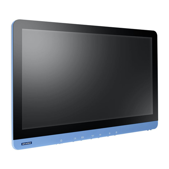
- Page 1 User Manual POC-624 Series 23.8” Point-of-Care Terminal with Intel® Core™ i7/i5/i3/ Celeron® Processor...
- Page 2 User Instructions/Instructions pour l'utilisateur This document combines text and illustrations to provide a comprehensive overview of the product. Information is presented as a sequential series of actions that allow users to learn directly how to use the device. The text also provides explanations and short, clear instructions regarding the installation and practical use of the product.
- Page 3 Safety Instructions Read these safety instructions carefully. Lisez attentivement ces consignes de sécurité. Retain this user manual for future reference. Gardez ce manuel pour référence future. Disconnect the equipment from all power outlets before cleaning. Use only a damp cloth for cleaning. Do not use liquid or spray detergents. Déconnectez cet équipement de toute prise secteur avant de le nettoyer.
- Page 4 Never pour liquid into an opening. This may cause fire or electrical shock. Ne jamais verser de liquide dans une ouverture. Cela peut provoquer un incendie ou un choc électrique. Never open the equipment. For safety reasons, the equipment should be opened only by qualified service personnel.
- Page 5 Warning! When servicing the device, always use replacement parts that are quali- fied to Advantech standards. Advantech Digital Healthcare cannot war- rant or endorse the safe performance of third-party replacement parts for use with our medical device.
- Page 6 Ensure that contact between SIP/SOPs and the patient does not occur. Assurez-vous que l'utilisateur n'autorise pas le contact simultané entre SIP/SOP et le patient. When networking with electrical devices, the operator is responsible for ensur- ing that the resulting system meets the requirements set forth by the following standards: Lors de la mise en réseau d'appareils électriques, il incombe à...
- Page 7 Advantech for more information. Utilisez uniquement le cordon d'alimentation fourni avec le produit, en cas de doute, veuillez contacter Advantech pour plus d'informations. The device is intended to be used as SIP/SOP when facing downward. L'appareil est destiné à être utilisé comme SIP/SOP orienté vers le bas.
- Page 8 Explanation of Graphical Symbols IEC 60878 and ISO 3864-B.3.6: Warning: dangerous voltage ISO 7000-0434: Caution, consult accompanying documents ISO 7000-1641: Follow operating instructions or consult instructions for IEC 60417 -5009: Standby IEC 60417-5032: Alternating current. AC model only IEC 60417-5031: Direct current IEC 60417-5021: Equipotentiality ISO 7010-M002: Follow instructions for use POC-624 User Manual...
- Page 9 Disposing of Old Products Within the European Union EU-wide legislation, as implemented in each member state, requires that all waste electrical and electronic products carrying the mark shown on the left must be disposed of separately from normal house- hold waste. This includes monitors and electrical accessories, such as signal cables and power cords.
- Page 10 Autrement, le fonctionnement adéquat de l’appareil serait compromis. Technical Support and Assistance Visit the Advantech website at www.advantech.com/support to obtain the latest product information. Contact your distributor, sales representative, or Advantech's customer service center for technical support if you need additional assistance. Please have the following information ready before calling: –...
-
Page 11: Table Of Contents
Contents Chapter General Information ......1 Introduction ....................2 Specifications .................... 2 Dimensions ....................3 Figure 1.1 POC-624 Terminal............3 Figure 1.2 VESA Mount ............... 4 Figure 1.3 POC-624 Front Panel ..........4 1.3.1 Optional Modules ................4 1.3.2 Cleaning and Disinfecting ............. 5 Operating Principle.................. - Page 12 Chapter VESA Mounting ......... 33 VESA Mount Installation ................. 34 Chapter Driver Installation......35 Windows Driver List ................36 Chapter PCM-8722 Connector Map....37 Figure 6.1 Motherboard Top Side View........38 Figure 6.2 Motherboard Bottom Side View........ 39 Chapter PCM-8722 Jumper Settings....
-
Page 13: Chapter 1 General Information
Chapter General Information... -
Page 14: Introduction
The front panel is IP65 rated for protection from water and dust ingress, facilitating regular cleaning for enhanced hygiene and infection control. Intended Use - The POC-624 series is designed to serve as general-purpose POC terminals that can be integrated with existing hospital systems and used for data col- lection/information displays. -
Page 15: Dimensions
Dimensions (W x D x H) 583 x 387 x 68 mm/22.95 x 15.2 x 2.68 in Physical Weight (Bare System) 7.78 kg/17.15 lb Characteristics VESA Mount 100x100, 75x75 Operating System Windows 10 IoT Enterprise (64 bit), Linux (upon request) Memory Up to 32 GB DDR4 SODIMM WLAN... -
Page 16: Optional Modules
Hot-Swappable Battery Pack: Optional with 2 x batteries (choose either backup battery or hot-swappable battery module) Camera: 1 x 5-megapixel camera (optional) Touchscreen: Optional AR coating/AG etching The above options may be mutually exclusive. Contact Advantech for more informa- tion. POC-624 User Manual... -
Page 17: Cleaning And Disinfecting
1.3.2 Cleaning and Disinfecting POC-624 terminals may become dirty during normal operation and thus should be cleaned regularly. Follow the steps below to clean the device. Steps 1. Prepare water for cleaning. 2. Moisten a clean cloth with the water. 3. -
Page 18: Intended User Profile
Intended User Profile Age: 18 ~ 65 years Weight: Not relevant Health: Not relevant Nationality: Global Patient state: Patient will not be the operator Part of the body or type of tissue applied to or interacted with: Hands and fingers ... -
Page 19: Chapter 2 System Setup
Chapter System Setup... -
Page 20: Quick Tour
Quick Tour Before setting up the POC-624 terminal, take a moment to familiarize yourself with the locations and functions of the controls, drives, connectors, and ports (refer to the figures below). When placed upright on a desktop, the POC-624 front panel should appear as shown in Figure 2.1. -
Page 21: Rear View
2.1.2 Rear View Located at the underside of the rear of the POC-624 terminal is the recessed I/O sec- tion, as shown in Figures 2.2 and 2.3. (The I/O section includes various I/O ports, including HDMI, Ethernet, USB, and serial ports.) Figure 2.2 POC-624 Rear View Figure 2.3 POC-624-11 Underside View 1. - Page 22 Figure 2.4 POC-624-01 Underside View 1. Headphones-Out 2. 1 x Mic-In 3. 2 x USB 2.0 4. 1 x PCIe x4 5. 1 x Equipotential terminal 6. 2 x USB 3.2 (Type A) 7. 2 x USB 2.0 8. 1 x USB 3.2 (Type C) 9.
-
Page 23: Installation Procedures
Installation Procedures 2.2.1 AC-In Power (for POC-624-01) The POC-624-01 model should be powered by an internal AC power supply (Model Number: FSP150M-K24-18). When handling power cords, always hold them by the plug ends only. Connect the female end of the power cord to the AC-In port. Connect the 3-pin male plug of the power cord to an electrical outlet. -
Page 24: Ground Pin Connection
Warning! Connecting the wrong cable to the DC-In socket may damage the POC terminal or adapter. Le plugin Miss direction peut endommager le système POC ou l'adapta- teur. 2.2.3 Ground Pin Connection An equipotential terminal is provided to facilitate connection to the ground/earthing system. -
Page 25: Bios Setup
Prepare the grounding cable by connecting one end to the hospital’s ground/ earthing system. Figure 2.7 Grounding Cable with Connector Connect the other side of the grounding cable to the equipotential terminal pin at the underside of POC-624 terminal. BIOS Setup Your POC-624 terminal was most likely setup and pre-configured by the vendor prior to delivery. -
Page 26: Driver Installation
Those files are a useful supplement to the information provided in this manual. Additionally, all drivers can be downloaded from the Advantech website. Troubleshooting If the POC-624 terminal is malfunctioning or does not operate according to the user manual, reference the sections below to troubleshoot the issue. -
Page 27: System Fails To Boot Into Windows
If the battery capacity exceeds this amount, the battery will not charge. 2.6.6 Technical Support Contact your distributor, sales representative, or Advantech's customer service cen- ter for technical support if you need additional assistance. Please have the following information ready before calling: Product name and serial number ... -
Page 28: Emc Declaration
EMC Declaration Guidance and Manufacturer’s Declaration – Electromagnetic Emissions POC-624 series terminals are intended for use in electromagnetic environments as specified below. The customer or user of a POC-624 terminal should ensure that it is used in such an environment. - Page 29 Guidance and Manufacturer’s Declaration – Electromagnetic Immunity POC-624 series terminals are intended for use in the electromagnetic environment specified below. The customer or user of a POC-624 terminal should ensure that it is used in such an environment. IEC 60601 Test...
- Page 30 Guidance and Manufacturer’s Declaration – Electromagnetic Immunity POC-624 series terminals are intended for use in the electromagnetic environment specified below. The customer or user of a POC-624 terminal should ensure that it is used in such an environment. IEC 60601 Test...
-
Page 31: Chapter 3 Operation And Safety
Chapter Operation and Safety... -
Page 32: General Safety Guide
Any internal parts need to be installed or removed (excluding the hot-swappable battery pack). Hot-Swappable Battery Module To ensure convenient operation, POC-624 series terminals also support an optional hot-swappable battery module (Part Number: POC-624-BAT-201-62), in which two battery packs can be installed. Battery Pack Installation Locate the blue doors (circled in red below) on either side of the battery module at the rear of the POC terminal. - Page 33 Locate the arrow push buttons next to the blue doors. Press the arrow push buttons and pull open the doors to access the battery module slot. POC-624 User Manual...
- Page 34 Insert the battery pack into the battery module. The module opening and battery packs feature notches (circled in red below) that indicate the correct installation direction. Caution! We recommend holding the battery pack with both hands when install- ing it into the battery module. Nous vous recommandons de tenir la batterie à...
- Page 35 Caution! Ensure that the mylar and pull ring (indicated in the image below) are returned to their original position (flat against the battery) before closing the door. Placez l'anneau de traction et le mylar (indiqués dans l'image ci-des- sous) à plat dans leur position d'origine (à plat contre la batterie) avant de fermer la porte.
-
Page 36: Thermal Management
Thermal Management The POC-624 terminal cover features vent holes that function as air inlets and outlets that transfer heat from inside the equipment to the cooler air outside. Do not block the holes/vents with any material. During operation, it is normal for the metal heatsink at the rear of the device to become warm. -
Page 37: Proper Handing
Warning! Never push objects through the openings in the case into the device as this may cause fire or electric shock. Never place anything on the case before powering off the device. Never power on the device if any of the internal or external parts have been removed. -
Page 38: Battery Warnings
Battery Warnings Read all safety instructions and warnings before using or charging the battery. Warning! Li-ion battery packs may explode and cause fire if defective or used incorrectly. To prevent this from happening, follow all usage instructions and safety guidelines provided in this user manual. Les batteries Li-ion peuvent exploser et provoquer un incendie si elles sont défectueuses ou mal utilisées. -
Page 39: Battery Safety
Battery Safety The POC terminal should only be powered by an Advantech battery pack or compatible battery pack supplied by Advantech. Warning! Do not insert non-Advantech battery packs into the POC terminal. Do not attempt to use battery packs of a different brand. - Page 40 Do not discharge the battery pack using any device other than the POC terminal or a device specified by Advantech. Warning! Using the battery pack to power devices other than the POC-624 termi- nal may damage the battery, limit performance, or reduce the battery capacity.
-
Page 41: Emergency Scenarios
If any of the above conditions are observed, place the battery pack and charger outside on a concrete floor, away from any flammable materials, for approximately 15 minutes and contact Advantech. Do not attempt to reuse the battery pack. In the event that the battery is leaking and the fluid gets into your eye, rinse well with water and seek immediate medical care. -
Page 42: Battery Storage And Transportation
3.10 Battery Storage and Transportation Store the battery in a dry environment with a room temperature of 0 ~ 25 °C (32 ~ 77 °F) for optimum health. Do not expose the battery pack to direct sunlight (heat) or store the battery pack inside vehicles in hot weather for extended periods. -
Page 43: Battery Disposal
3.11 Battery Disposal When the battery pack has reached the end of its service life, do not use general household waste for disposal. Follow local laws and government regulations for cor- rect battery disposal. Caution! Cover terminals with tape to prevent inadvertent contact with other bat- teries or metal objects. - Page 44 POC-624 User Manual...
-
Page 45: Chapter 4 Vesa Mounting
Chapter VESA Mounting... -
Page 46: Vesa Mount Installation
VESA Mount Installation The POC-624 series terminals support VESA mounting, allowing system integrators to conveniently integrate the device into various computing infrastructures. To pre- vent unreliable and dangerous mounting, only use mount brackets provided by Advantech. Additionally, we recommend that mount installation be conducted by a qualified service technician according to the instructions provided below. -
Page 47: Chapter 5 Driver Installation
Chapter Driver Installation... -
Page 48: Windows Driver List
The POC-624 series terminals support the Windows 10 IoT (64 bit), RS5 version or later, operating system. However, the 32-bit driver is no longer supported. Warning! Conduct a clean installation of the OS before installing the drivers to avoid unexpected errors. -
Page 49: Chapter 6 Pcm-8722 Connector Map
Chapter PCM-8722 Connector... - Page 50 The POC-624 series terminals feature a PCM-8722 printed circuit board assembly. Figure 6.1 Motherboard Top Side View POC-624 User Manual...
- Page 51 Figure 6.2 Motherboard Bottom Side View POC-624 User Manual...
- Page 52 POC-624 User Manual...
-
Page 53: Chapter 7 Pcm-8722 Jumper Settings
Chapter PCM-8722 Jumper Settings... - Page 54 The POC-624 series terminals feature a PCM-8722 printed circuit board assembly. All jumpers and DIP switches are located on the top side of the motherboard. Figure 7.1 Motherboard Top Side Jumper Settings ME Manufacturing Mode Clear CMOS Clear ME (reserved, not installed)
- Page 55 ME Manufacturing Mode Description ME manufacturing mode Setting Function (1-2) ME manufacturing mode (Not connected) Normal operation (default) Clear CMOS Description Clear CMOS setup Setting Function (1-2) Clear CMOS setup (Not connected) Normal operation (default) CN6 (Not Installed) Clear ME Description Clear ME setup Setting...
- Page 56 CN13 LVDS Voltage Setup Description Select panel LVDS voltage setting Setting Function (1-2) Panel LVDS voltage 5V (default) (2-3) Panel LVDS voltage 3.3V CN40 Power Button (Internal Test Only) Description Power button signal Setting Function (Pin 2) Short pin 1 to power on (Not connected) Normal operation (default) PCN4...
- Page 57 SW1 Pin 1 SW1 Pin 2 SW1 Pin 3 Board Configuration High (Off) High (Off) High (Off) Board Config 1 (default) High (Off) High (Off) Low (On) Board Config 2 High (Off) Low (On) High (Off) Board Config 3 High (Off) High (Off) High (Off) Board Config 4...
- Page 58 Different System Summary POC-624 terminal POC-624, without audio board, 5V LVDS panel SW1 Pin 1 SW1 Pin 2 SW1 Pin 3 SW1 Pin 4 SW2 Pin 1 SW2 Pin 2 SW2 Pin 3 SW2 Pin 4 CN13 High (Off) High (Off) High (Off) High (Off) Low (On) High (Off) High (Off) High (Off) (1-2) POC-624 User Manual...
-
Page 59: Chapter 8 Front Panel Buttons
Chapter Front Panel Buttons... -
Page 60: Front Panel Function Buttons
Front Panel Function Buttons Button Description Power Button Press this button to power on/off the device. When the device is on, this icon will emit green light. When the device is off, the LED indicator will be off. Reduce Volume Press this button to reduce speaker and headphone volume. -
Page 61: Chapter 9 Advanced Bios Function
Chapter Advanced BIOS Function... -
Page 62: Additional Bios Utility Functions
Additional BIOS Utility Functions Power Button Function Users can enable/disable power button function in the BIOS utility. If the power button function is disabled when the device is in S0 (System On) status, the user will not be able to power off the device using the power button. Instead, the user will need to power off the device via software. - Page 63 Reading Light Button Function Users can enable/disable the reading light button function in the BIOS utility. If the reading light button function is disabled, users will not be able to turn on the reading light using this button. Thus, the reading light function will be always off.
- Page 64 No part of this publication may be reproduced in any form or by any means, such as electronically, by photocopying, recording, or otherwise, without prior written permission from the publisher. All brand and product names are trademarks or registered trademarks of their respective companies. © Advantech Co., Ltd. 2021...
Need help?
Do you have a question about the POC-624 Series and is the answer not in the manual?
Questions and answers