
Related Manuals for KYORITSU 6011A


Summary of Contents for KYORITSU 6011A
- Page 1 INSTRUCTION MANUAL MULTI-FUNCTION TESTER MODEL 6 0 1 0A KYORITSU ELECTRICAL INSTRUMENTS WORKS, LTD.
-
Page 2: Table Of Contents
CONTENTS 1.Safe Testing................... 1 2.Features..................3 3.Specification................... 6 4.Continuity (resistance) tests............9 4. 1 Instrument layout..............9 4. 2 Resistance of test leads ............9 4. 3 Continuity testing ..............10 5.Insulation Tests................11 5. 1 The nature of insulation resistance........11 5.... -
Page 3: Safe Testing
1.This instrument must only be used by a competent and trained person and operated in strict accordance with the instructions. KYORITSU will not accept liability for any damage or injury caused by misuse or non- compliance with the instructions or with the safety procedures. - Page 4 9.For safety reasons only use accessories (test leads, probes, fuses, cases, etc) designed to be used with this instrument and recommended by KYORITSU. The use of other accessories is prohibited as they are unlikely to have the correct safety features.
-
Page 5: Features
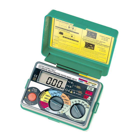
2. FEATURES LIVE CIRCUIT LED WIRING CHECK CONNECTOR LCD DISPLAY RCD RATED TRIPPING FUNCTION SWITCH TEST BUTTON CURRENT SWITCH LCD DISPLAY Test Lead with IEC Connector Test Lead for Continuity and Insulation Testing Fig.1 ― 3 ―... - Page 6 Model 6010A Multi-Function tester performs five functions in one instrument. 1.Continuity tester 2.Insulation resistance tester 3.Loop impedance tester 4.RCD tester 5.Mains voltage warning when operating the loop impedance and RCD mode. The tester is designed to Safety Standard IEC 61010-1/EN 61010-1 CAT III (300V).
- Page 7 Over temperature protection Detects overheating of the internal resistor (used for loop and RCD tests) and of the current control MOS FET (used for RCD tests) displaying a warning symbol ( ) and automatically halting further measurements. Phase angle selector The test can be selected from either the positive (0 ™...
-
Page 8: Specification
3. SPECIFICATION Measurement Specification Continuity (to IEC61557-4) Open Circuit Short Circuit Range Accuracy Voltage(DC) Current 20/200Ω Auto-Ranging Greater than Greater than 4V 200mA Up to 2Ω ±(3%rdg+4dgt) Over 2Ω ±(3%rdg+3dgt) Operating range(as in IEC61557) 20Ωrange:0.2Ω∼19.99Ω/200ΩRange:20Ω∼199.9Ω Insulation Resistance (to IEC61557-2) Open Circuit Rated Current Range Accuracy... - Page 9 To prevent wrong connection of test leads and to maintain safety, the dedicated terminals used for continuity and insulation tests are automatically covered when using the terminals for loop impedance and RCD tests 175 X 115 X 86mm Instrument dimensions 780g including batteries.
- Page 10 is updated approximately five times per second. The continuity test circuit is protected by a 0.5 A Overload protection 600 V fast acting(HRC) ceramic fuse mounted in the battery compartment, where a spare fuse is also stored. The insulation resistance test circuit is protected by a resistor against 600 V AC for 10 seconds.
-
Page 11: Continuity (Resistance) Tests
4. CONTINUITY (RESISTANCE) TESTS WARNING ENSURE THAT CIRCUITS TO BE TESTED ARE NOT LIVE. DISCONNECT THE INSTRUMENT FROM THE CIRCUIT UNDER TEST BEFORE OPERATING THE FUNCTION SWITCH. TO SELECT THE LOW RESISTANCE RANGE SELECT“CONTINUITY” 4. 1 Instrument layout See Fig 1. 4.... -
Page 12: 4. 3 Continuity Testing
4. 3 Continuity testing TEMPORARY LINK test at socket between L and E Fig 3 1.Press the test button once. Then, the instrument switches on. 2.Select the continuity test by rotating the function dial. 3.Connect the test leads to the circuit whose resistance is required(see Fig 3)HAVING FIRST MADE SURE THAT THE CIRCUIT IS NOT LIVE. -
Page 13: Insulation Tests
5. INSULATION TESTS WARNING ENSURE THAT CIRCUITS TO BE TESTED ARE NOT LIVE. DISCONNECT THE INSTRUMENT FROM THE CIRCUIT UNDER TEST BEFORE OPERATING THE FUNCTION SWITCH. TO S E LE CT TH E I N S U L ATI O N R E S I STAN C E R AN G E S E LE CT “INSULATION”... -
Page 14: 5. 1. 3 Conduction Current
Fig 4 5. 1. 3 Conduction Current Since the insulation resistance is not infinite, a small leakage current flows through the insulation between conductors. Since Ohm's Law applies, the leakage current can be calculated from applied voltage (V) Leakage current (µA) = insulation resistance (MΩ) Fig 5 5.... -
Page 15: 5. 1. 5 Total Leakage Current
5. 1. 5 Total Leakage Current The total leakage current is the sum of the capacitive, conduction and surface leakage current described above. Each of the currents, and hence the total leakage current, is affected by factors such as ambient temperature, conductor temperature, humidity and the applied voltage. -
Page 16: 5. 3 Preparation For Measurement
¡ Electronic fluorescent starter switches ¡ Passive infra-red detectors (PIRs) ¡ Dimmer switches ¡ Touch switches ¡ Delay timers ¡ Power controllers ¡ Emergency lighting units ¡ Electronic RCDs ¡ Computers and printers ¡ Electronic point-of-sale terminals (cash registers) ¡ Any other device which includes electronic components. 5.... - Page 17 Equipment disconnected All fuses in or circuit breakers closed Mains Switch off Switches closed Lamps out Reading not less than 0.5 MΩ Main switch open Fig 7 4.If the mains warning lamp lights and/or the buzzer sounds DO NOT PRESS THE TEST BUTTON but disconnect the instrument from the circuit.
- Page 18 7.When testing is complete release the test button BEFORE disconnecting the test leads from the circuit or from the appliance. This will ensure that the charge built up by the circuit or the appliance during insulation test is dissipated in the discharge circuit. In the discharging process, an LED illuminates and the live circuit warning buzzer will sound.
-
Page 19: Loop Impedance Tests
6. LOOP IMPEDANCE TESTS DISCONNECT THE INSTRUMENT FROM THE CIRCUIT UNDER TEST BEFORE OPERATING THE FUNCTION SWITCH TO SELECT THE LOOP TESTING RANGE SELECT“LOOP” 6.1 Voltage Measurement Press the test button once. Then, the instrument switches on.When the tester is set to the loop test function, mains voltage is displayed as soon as the instrument is connected for test. - Page 20 only be carried out after the mains supply has been connected. In many cases, any RCD in the circuit will be tripped by this test, which draws current from the phase and returns it through the earth system. The RCD will see this as the type of fault it is designed to protect against, and will trip.
-
Page 21: Loop Impedance At 3 Phase Equipment
the reduced current of 15mA flowing.This setting will be very unlikely to trip out the circuit RCD. Note:Do not connect phase to phase as this instrument is rated at 230V. 6.5 Loop impedance at 3 phase equipment Use the same procedure as in 6.4 above ensuring that only one phase is connected at a time i.e.:First Test: red prod to phase 1, black prod to neutral, green crocodile clip to earth. - Page 22 Fig 9 BLACK NEUTRAL RED PHASE GREEN EARTH Fig 10 ― 20 ―...
-
Page 23: Rcd Tests
7. RCD TESTS DISCONNECT THE INSTRUMENT FROM THE CIRCUIT UNDER TEST BEFORE OPERATING THE FUNCTION SWITCH TO SELECT THE RCD TEST RANGE SELECT“RCD” 7.1 Purpose of the RCD test The RCD must be tested to ensure that operation takes place quickly enough to ensure that there is unlikely to be serious danger to a person experiencing an electric shock from the system. -
Page 24: Testing Rcds Used To Provide Supplementary Protection
10.Set the function switch to X1 for the“trip”test, which measures the time taken for the RCD to trip with the set residual current. 11.Set the "LOOP/RCD" switch to 0゜ 12.Make sure that the P-E and P-N wiring check lamps are lit. If they are not, disconnect the tester and check the wiring for a possible fault. -
Page 25: General
maximum of 2000ms on the X1/2 and X1 ranges. The fact that the RCD has not tripped will be evident because the PN and PE LEDs will still be On RCD ranges, when the N-E voltage rises to 50V or greater, the measurement is automatically suspended and "VNE Hi"... -
Page 26: Battery Replacement
9. BATTERY REPLACEMENT When the display shows the low battery indication, ( ), disconnect the test leads from the instrument. Remove the battery cover and the batteries. Replace with eight (8) new 1.5 V R6 or LR6 batteries, taking care to observe correct polarity. -
Page 27: Servicing
11. SERVICING If this tester should fail to operate correctly, return it to your distributor stating the exact nature of the fault. Before returning the instrument ensure that:- 1.The leads have been checked for continuity and signs of damage. 2.The continuity mode fuse (situated in the battery compartment) has been checked. -
Page 28: Case, Strap And Shoulder Pad Assembly
12. CASE, STRAP AND SHOULDER PAD ASSEMBLY Correct assembly is shown in Fig 12. By hanging the instrument round the neck, both hands will be left free for testing. ① Pass the strap DOWN through the first case lug,under the case and UP through the other lug. - Page 29 M E M O ― 27 ―...
- Page 30 M E M O ― 28 ―...
- Page 31 M E M O ― 29 ―...
- Page 32 DISTRIBUTOR 92-1455B 00-08 KYORITSU ELECTRICAL INSTRUMENTS WORKS, LTD. No.5-20, Nakane 2― chome, Meguro-ku, Tokyo, 152-0031 Japan Phone: (03) 3723― 0131 Telex:0246― 6703 Fax: (03) 3723― 0152 Cable Address:"KYORITSUKEIKI"TOKYO URL:http://www.kew-ltd.co.jp E-mail:info@kew-ltd.co.jp Factories:Uwajima&Ehime...
Need help?
Do you have a question about the 6011A and is the answer not in the manual?
Questions and answers
Методика поверки kyoritsu kew 6011а