
Related Manuals for KYORITSU 4116A


Summary of Contents for KYORITSU 4116A
- Page 1 INSTRUCTION MANUAL DIGITAL PSC-LOOP TESTER MODEL 4116A, 4118A, 4120A KYORITSU ELECTRICAL INSTRUMENTS WORKS, LTD.
-
Page 2: Table Of Contents
CONTENTS 1. SAFE TESTING ................ 1 2. PROCEDURE OF REMOVING COVER ......... 3 3. FEATURES .................. 4 3.1 Instrument Layout .............. 4 3.2 Test Lead .................. 5 3.3 Features ................... 5 4. SPECIFICATIONS ................ 7 5. OPERATING INSTRUCTIONS ............ 8 5.1 Initial Checks ................ 8 5.2 Measurement of the Loop Impedance ........ 9 5.3 Measurement of Prospective Short Circuit Current .... 10 6. DETAILED EXPLANATION ............ 10 6.1 Measurement of Fault Loop Impedance and Prospective Fault Current ............ 10 6.2 Measurement of OLD-TT System .......... 15 6.3 Measurement of Line Impedance and Prospective Short Circuit Current .......... 16 7. SERVICING ................... 17 8. CASE AND STRAP BELT ASSEMBLY ......... 17... -
Page 3: Safe Testing
Therefore, read through these operating instructions before using the instrument. IMPORTANT: 1. This instrument must only be used by a competent and trained person and operated in strict accordance with the instructions. KYORITSU will not accept liability for any damage or injury caused by misuse or non-compliance with the instructions or with the safety procedures. 2. It is essential to read and to understand the safety rules contained in the instructions or with the safety procedures. - Page 4 ● Never attempt to use the instrument if the instrument or your hand is wet. CAUTION ● For those testers without the D-LOK circuitry (models 4116A, 4118A) all RCD's (RCCB, ELCB) in the circuit must be by-passed for the duration of the test (except on loop-2000Ω range). Do not operate the RCD Test Button with the RCD by-passed. ● During testing it is possible that there may be a momentary degradation of the reading due to the presence of excessive transients ...
-
Page 5: Procedure Of Removing Cover
2. PROCEDURE OF REMOVING COVER Model 4116A, 4118A and 4120A have a dedicated cover to protect against an impact from the outside and prevent the operation part, the LCD and the connector socket from becoming dirty. The cover can be detached and put on the back side of the main body during measurement. 2.1 Method of removing the cover Fig. 1 2.2 Method of housing the cover Fig. 2 ― 3 ―... -
Page 6: Features
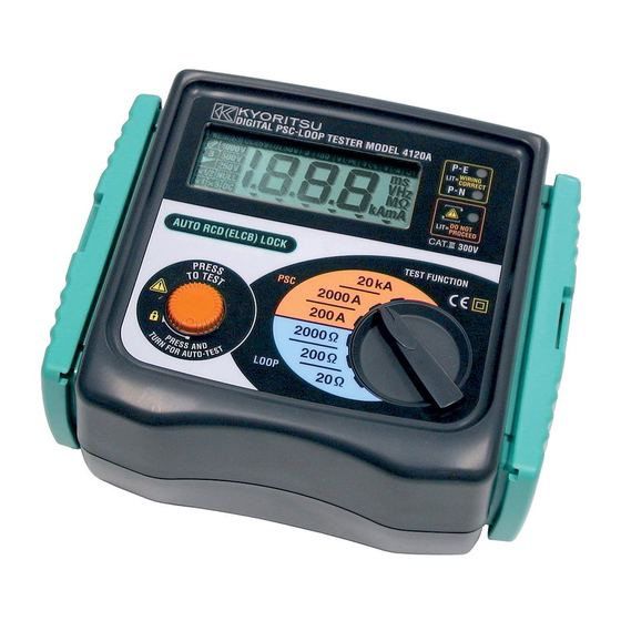
3. FEATURES 3.1 Instrument Layout ⑤ ① ② Wiring correct (Green LED's) Reversed L/N terminals (Red LED) ③ ④ Connector Fig. 3 1.... LCD display 2.... Wiring check LEDs 3... Test button 4.... Range switch 5.... Connector DANGER ● Use original test lead only. ● Max. allowed voltage between mains test terminals and ground is 300V. ● This instrument is intended only for use in single phase operation at 230V +10% -15% AC phase to earth or for use in OLD-TT system phase to neutral. ―... -
Page 7: Test Lead
3.2 Test Lead The instrument is supplied with Model 7125 lead at socket outlets and Model 7121 distribution board lead. (1) Model 7125 (2) Model 7121 (Included as standard equipment for M-4118A and 4120A. Optional for M-4116A.) Black-Neutral Red-Phase Green-Earth Fig.4 3.3 Features 3.3-1 Test Range (Function): Model M-4120A M-4118A M-4116A ○ × × D-LOK Circuit * Loop 0-19.99Ω/ ○ ○ ○ 0-199.9Ω/0-1999Ω PSC 0-199.9A/ ○ ○ × 0-4.00kA 0-1999A/ Note: ● *D-LOK=Automatic device (RCD) lock ● D-LOK dose not operate on the Loop-2000Ω. ● Mains voltage with which D-LOK operates is as shown in the table below. Range D-LOK Operating Voltage Loop200Ω/PSC200A... - Page 8 3.3-3 Model 4116A, 4118A and 4120A have the following features: ● Battery is not used All models are not battery-operated, but operate by the voltage supplied from the system. ● Wiring check Three LEDs indicate if the wiring of the circuit under test is correct. The P-E and P-N LEDs illuminate when the wiring polarity of the circuit under test is correct. The Reverse LED is lit when P and N are reversed.
-
Page 9: Specifications
20kA 0.00 〜 4.00kA 25A / 20ms Voltage Measuring range Accuracy 110 〜 260V ±(2%rdg + 4dgt) Instrument dimensions 186×167×89mm Instrument weight M-4120A / 960g, M-4116A and M-4118A / 750g Reference conditions Specifications are based on the following conditions except where otherwise stated: 1. Ambient temperature: 23 ± 5 ℃ 2. Relative humidity:45% to 75% 3. Position: horizontal 4. AC power source: 230V, 50Hz 5. Altitude: Up to 2000m Operating temperature 0 to +40℃, relative humidity 80% or less, no and humidity condensation. -
Page 10: Operating Instructions
● Operating Error of Loop Impedance (61557-3) Measuring range to keep Maximum percentage Range operating error operating error 20Ω 0.20 〜 19.99Ω 200Ω ±30% 20.0 〜 199.9Ω 2000Ω 200 〜 1999Ω The influencing variations used for calculating the operating error are denoted as follows: Temperature:0℃ and 40℃ Phase angle :At a phase angle 0゜to 18゜ System frequency:49.5Hz to 50.5Hz System voltage:230V+10%-15% 5. OPERATING INSTRUCTIONS 5.1 Initial Checks - To be carried out before any testing. (1) Test Lead Connection Insert the lead plug into the connector on the instrument correctly as shown below. -
Page 11: Measurement Of The Loop Impedance
WARNING ● If the above sequence is NOT displayed or the RED LED is on for any reason , DO NOT PROCEED AS THERE IS INCORRECT WIRING. The cause of the fault must be investigated and rectified. (3) Voltage Measurement When the instrument is first connected to the system, it will display the phase-neutral voltage which is updated every 1s. This mode is cancelled whenever the test button is pressed. If this voltage is not normal or as expected, DO NOT PROCEED. WARNING ● This instrument is intended only for use in single phase operation at 230V +10% -15% AC phase to earth or for use in OLD-TT system phase to neutral. -
Page 12: Measurement Of Prospective Short Circuit Current
5.3 Measurement of Prospective Short Circuit Current − (Models 4118A and 4120A) (1) Set the instrument to the 20kA range. (2) Connect the test lead to the instrument. (3) Attach the plug to the socket to be tested. (4) Check that the LED's are lit in the sequence indicated in section 5.1. If not, disconnect from the mains and check the wiring at the socket. (5) Press the "Press to Test" button. The prospective short circuit current (PSC) will be directly displayed on the LCD with the appropriate units. This will remain for 3s and then revert to AC voltage display. An audible beep will sound on completion of the test. For best results always test on the lowest possible range. For example a PSC measured on the 2000A range may read 60A whilst on the 200A range it may read 56.0A. To hold the reading keep the button held down or turn clockwise to lock for Auto Test. Note: ● For loop impedance greater than 210Ω on PSC 200A range and 25 Ω on 2000A, 20kA ranges, the fault voltage may become high and dangerous due to the D-LOK current, therefore, the unit is designed to lock out PSC ranges showing "Uf-Hi" symbol. Normally PSC tests are conducted at point of origin, e.g. distribution boards, between phase and neutral. When conducting PSC tests at socket outlets, a test will be conducted between phase and earth due to the fixed wiring of the moulded mains plug. - Page 13 In the event of a fault, the Fault loop impedance should be low enough (and the Prospective Fault current higher enough) in order to have the automatic disconnection of supply by the installed protection device within prescribed time interval. Every circuit must be tested to make sure that the fault loop impedance does not exceed that specified for the over current protection device concerned.
- Page 14 ⊿ For instance in a TT system protected by a RCD the max RA values are: Rated residual operating current I⊿n. 1000 RA (at 50V) 5000 1667 Ω 2500 Ω RA (at 25V) Note: ● The loop tester models 4120A / 4118A / 4116A measure the fault loop impedance that is a value normally a little bit higher of RA. But, if the electrical installation is protected considering the loop impedance value, also the RA formula will be fulfilled. ― 12 ―...
- Page 15 Practical example of verification of the protection in a TT system according to the international Standard IEC 60364. RCD 30mA Fig.8 For this example max value is 1667Ω, the loop tester reads 12.74Ω, it means that the condition RA < 50/Ia is respected. It is fundamental for this example to test also the RCD to ensure that operation takes place quickly enough to respect the safety requirements. In order to do it, can be used the RCD tester model 5406A. According to the international Standard IEC 60364 for TN system the following condition shall be fulfilled for each circuit: <...
- Page 16 For instance in a TN system with nominal mains voltage Uo = 230 V protected by gG fuses the Ia and max Zs values could be: Disconnecting time 5s Disconnecting time 0.4s Rating Ia (A) Zs (Ω) Ia (A) Zs (Ω) 1.56 1.25 1.53 0.83 1.21 0.72 0.92 0.49 0.71 0.42 0.54 0.27 0.39 1020 0.22 Using the current ranges on models 4120A and 4118A can be also tested the Prospective Fault current. ...
-
Page 17: Measurement Of Old-Tt System
Max value of Zs for this example is 2.1Ω (16A gG fuse, 0.4s) the loop tester reads 1.14Ω (or 202 A on Fault current range) it means that the condition Zs < Uo/Ia is respected. In fact the Zs of 1.14Ω is less than 2.1Ω (or the Fault current of 202 A is more than Ia of 110A). WARNING ● This instrument is intended only for use in single phase operation at 230V +10% -15% AC phase to earth or for use in OLD-TT system phase to neutral. ● If the overheat symbol appears in the display ( ) disconnect the instrument from the mains supply and allow to cool down. 6.2 Measurement of "OLD-TT System" OLD-TT system is a TT system with phase to phase voltage of 220 V (instead ... -
Page 18: Measurement Of Line Impedance And Prospective Short Circuit Current
WARNING (OLD-TT system only) ● DO NOT PRESS the "Test button" if the display reads a value of 220V! The RCD could trip during the tests also with model 4120A. CAUTION ● The D-LOK circuit of 4120A can not works with 127V between phase to earth. 6.3 Measurement of Line Impedance and Prospective Short Circuit Current Line Impedance on single-phase system is the impedance measured between phase and neutral terminals. Measurement principle used inside the instrument is exactly the same as at Fault Loop Impedance measurement, but the measurement is carried out between L and N terminals. -
Page 19: Servicing
WARNING ● This instrument is intended only for use in single phase operation at 230V +10% -15% AC phase to earth or for use in OLD-TT system phase to neutral. ● If the overheat symbol appears in the display ( ) disconnect the instrument from the mains supply and allow to cool down. ● When testing installation that has a large current capacity, such as a power line, be sure not to short live conductors with the tip of a probe. Failure to follow these instruction can cause hazards to the user. 7. SERVICING If this tester should fail to operate correctly, return it to your distributor stating the exact nature of the fault. Please remember to give all the information possible concerning the nature of the fault, as this will mean that the instrument will be serviced and returned to you more quickly. - Page 20 DISTRIBUTOR 92-1483 01-05 Kyoritsu reserves the rights to change specifications or designs described in this manual without notice and without obligations.
Need help?
Do you have a question about the 4116A and is the answer not in the manual?
Questions and answers