Table of Contents
Advertisement
Advertisement
Table of Contents

Related Manuals for KYORITSU KEW 6016


Summary of Contents for KYORITSU KEW 6016
- Page 1 INSTRUCTION MANUAL MULTI-FUNCTION TESTER KEW 6016...
-
Page 2: Table Of Contents
CONTENTS Safe Testing ……….…………………………………………………………….….……. 1 Instruments Layout …………………………………………………………..……... 3 Accessories ………………………………………………………………………….. 5 Features ……………………………………………………………………………… 6 Specification …………………………………………………………………………. 8 5.1 Measurement Specification …………………………………………………. 8 5.2 Operating error ………………………………………………………….……. 11 5.3 General Specification ….…………………………………………………….. 13 5.4 Applied standards …………………………………………………………….. 14 5.5 List of Display Message .…………………………………………………….. 15 Configuration …………………………………………………………………………... - Page 3 Back Light………………………………………………………………………………… 46 Memory Function………………………………………………………………………… 47 16.1 H ow t o s ave th e d at a……… ………… …………… ……………… … … 47 16.2 R ec all th e s aved d at a…………… ………………… ………………… … 49 16.3 D elet e th e s aved d at a……...
-
Page 4: Safe Testing
8 For safety reasons only use accessories (test leads, probes, fuses, cases, etc) designed to be used with this instrument and recommended by KYORITSU. The use of other accessories is prohibited as they are unlikely to have the correct safety features. - Page 5 11 Do not operate the function selector while the instrument is connected to a circuit. If, for example, the instrument has just completed a continuity test and an insulation test is to follow, disconnect the test leads from the circuit before moving the selector switch. 12 Do not rotate rotary switch when test button is depressed.
-
Page 6: Instruments Layout
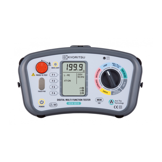
2. INSTRUMENT LAYOUT Fig.1 Name Operation Back Light Button Switches on/off the Backlight of the Display(LCD) Test Button Starts measurements. (press and rotate for lock down feature) Touch Pad Checks the electrical potential at the PE terminal Power Switch Power Switch Function Switch Function setting (F1 ~ F4) Display (LCD) - Page 7 Input Terminal Fig.2 Function Terminal Terminal Names for : L : Line INSULATION, PE : Protective Earth CONTINUITY LOOP, PFC/PSC, N : Neutral (for LOOP,PSC/PFC, RCD) RCD, VOLTS L1 : Line1 Terminal Name for L2 : Line2 PHASE ROTATION L3 : Line3 H(C) : Terminal for auxiliary earth spike (current) Terminal Name for...
-
Page 8: Accessories
3. Accessories 1.Main Test Lead (Model7218) Red(Line) Green(Protective Earth) Fig.3 Blue(Neutral) 2.Remote Test Lead (Model 7196) Fig. 4 3.Distribution Board fused test lead (Model7188) (Fuse: 10A/600V fast acting ceramic) Red(Line or L1) Green(Protective Earth or L2) Blue(Neutral or L3) Fig. 5 4. -
Page 9: Features
4. FEATURES The KEW6016 Multi-Function tester performs eight functions in one instrument. 1 Continuity tester 2 Insulation resistance tester 3 Loop impedance tester 4 Prospective short circuit current tester 5 RCD tester 6 Voltage tester 7 Phase rotation tester 8 Earth tester Continuity function has the following features: Live circuit warning “Live Circuit”... - Page 10 Loop impedance, PSC/PFC and RCD testing functions have the following features: Wiring check Three Wiring symbols indicate if the wiring of the circuit under test is correct. Over temperature Detects overheating of the internal resistor (used for LOOP and protection PSC/PFC tests) and of the current control MOS FET (used for RCD tests) displaying a warning symbol and automatically halting further measurements.
-
Page 11: Specification
5. Specification 5.1 Measurement Specification Continuity Open Circuit Short Circuit Accuracy Range Voltage (DC) Current Greater than 20/200/2000Ω 0~0.19Ω ±0.1Ω 5V±20%(*1) 200mA Auto-Ranging 0.2~2000Ω ±(2%rdg+8dgt) 2Ω Buzzer : Buzzer sounds when measured resistance is 2Ω or less. 2Ω Buzzer Accuracy : 2Ω±0.4Ω (*1) Voltages are output when measurement resistance is under 2100 ohm. - Page 12 PSC (L-N/L-L) / PFC (L-PE) Nominal Test Current Rated Range Accuracy at 0Ω External Loop: Function Voltage Magnitude/Duration(*5) 100~500V PSC/PFC 6A/20ms 50/60Hz accuracy is derived from 6A/20ms 100~260V measured loop 2A/20ms 2000A/20kA 50/60Hz Auto-Ranging impedance 15mA/500ms specification and 100~260V L-N: 6A/60ms measured voltage (ATT) 50/60Hz...
- Page 13 RCD Trip Current Duration RCD Trip Current Duration Function Type 1000 2000 2000 2000 2000 2000 2000 2000 2000 2000 2000 2000 X1/2 2000 2000 2000 2000 2000 2000 2000 2000 2000 2000 Trip 1000 1000 1000 1000 1000 Current 1000 1000 1000...
-
Page 14: Operating Error
Possible number of tests with fresh batteries. Continuity :Approx. 2000 times min. at load 1Ω Insulation Resistance :Approx. 1000 times min. at load 1MΩ (1000V) LOOP/PFC/PSC :Approx. 1000 times min. (ATT) :Approx. 2000 times min. (G-AC X1 30mA) EARTH :Approx. 1000 times min. at load 10Ω VOLT/PHASE ROTATION :Approx. - Page 15 Loop Impedance(EN61557-3) Operating range compliant with Maximum percentage Volt EN61557-3 operating error operating error L-PE 0.50~1999Ω ±30% 0.50~19.99Ω The influencing variations used for calculating the operating error are denoted as follows; Temperature : 0 C and 35 Phase angle : At a phase angle 0°to 18° System frequency : 49.5Hz to 50.5Hz System voltage : 230V+10%-15% Supply voltage : 8V to 13.8V...
-
Page 16: General Specification
Earth Resistance (EN61557-5) Operating range compliant with EN61557-5 Maximum percentage operating error operating error 5.00~1999Ω ±30% The influencing variations used for calculating the operating error are denoted as follows; Temperature : 0 C and 35 Series interference voltage : 3V Resistance of the probes and auxiliary earth electrode resistance : 100 x RA, 50kΩ... -
Page 17: Applied Standards
5.4 Applied standards Instrument operating IEC/EN61557-1,2,3,4,5,6,7,10 Standard Safety standard IEC/EN 61010-1(2001), CATIII (300V) -Instrument IEC/EN 61010-031(2001), CATII (250V)-Test Lead Model7218 CATIII (600V)-Test Lead Model7188 CATIII (1000V)-Test Lead Model7196 CATIII (300V)-Test Lead Model7228 Protection degree IEC 60529 (1989 + A1) IP40 EN 61326 EN55022/24 This manual and product may use the following symbols... -
Page 18: List Of Display Message
5.5 List of Display Message Low battery warning Temperature monitor for internal resistance, available at Loop, PSC/PFC & RCD function. Further measurements are suspended until the “ ” symbol disappears. Measuring Measurements in progress Live Circuit Live circuit warning (Continuity / Insulation Function) PE Hi V Caution : Presence of 100V or more at PE terminal, appears when touching the Touch Pad... -
Page 19: Configuration
6. Configuration Setting for following three parameters ● UL value Selects a UL value for RCD function ● Touch Pad Enables / disables Touch Pad function ● Back Light Selects Backlight ON / OFF. When ON is selected, the Backlight automatically turns on at powering on the instrument. ●... -
Page 20: Continuity(Resistance) Tests
7. CONTINUITY (RESISTANCE) TESTS WARNING Ensure that circuits to be tested are not live. Disconnect the instrument from the circuit under test before operating the function switch. To select the low resistance range select ‘CONTINUITY’. 7.1 Test Procedure The object of continuity testing is to measure only the resistance of the parts of the wiring system under test. - Page 21 Ω NULL Ω NULL Fig.13 4 Operate the Continuity Null (F1) button, this will null out the lead resistance and the indicated reading should go to zero. 5 Release the test button. Press the test button and ensure the display reads zero before proceeding.
-
Page 22: Buzzer
MAIN EQUIPOTENTIAL BONDING WATER Ω NULL Fig.14 Example of continuity test for main equipotential bonding. 7.2 2Ω Buzzer ( ) function Use F2 Button to enable / disable the 2Ω Buzzer. The buzzer sounds when measured resistance is 2Ω or less while this function is enabled. The buzzer does not sound if it is disabled. -
Page 23: Insulation Tests
8. INSULATION TESTS WARNING Ensure that circuits to be tested are not live. Disconnect the instrument from the circuit under test before operating the function switch. To select the insulation resistance range select ‘INSULATION’. 8.1.1 The nature of insulation resistance Live conductors are separated from each other and from earth metal by insulation, which has a resistance which is high enough to ensure that the current between conductors and to earth is kept at an acceptably low level. -
Page 24: Conduction Current
8.1.3 Conduction Current Since the insulation resistance is not infinite, a small leakage current flows through the insulation between conductors. Since Ohm's Law applies, the leakage current can be calculated from Fig.16 8.1.4 Surface Leakage Current Where insulation is removed, for the connection of conductors and so on, current will flow across the surfaces of the insulation between the bare conductors. -
Page 25: Damage To Voltage Sensitive Equipment
present and can never be eliminated. This is why a direct voltage is used for insulation resistance measurement, the leakage current in this case quickly falling to zero so that it has no effect on the measurement. A high voltage is used because this will often break down poor insulation and cause flashover due to surface leakage (see 8.1.4), thus showing up potential faults which would not be present at lower levels. -
Page 26: Preparation For Measurement
● Any other device which includes electronic components. 8.3 Preparation for measurement Before testing, always check the following:- 1 The ‘low battery’ Indication is not displayed 2 There is no visually obvious damage to the tester or to the test leads 3 Test the continuity of the test leads by switching to continuity test and shorting out the lead ends. - Page 27 4 Attach the test leads to the circuit or the appliance under test (see Figs 20 & 21) MΩ 1000V Fig.20 Example of Insulation resistance test on 4 wire-3 phase system. 5 If the “Live Circuit” warning is displayed on the LCD and/or the buzzer sounds, do not press the test button but disconnect the instrument from the circuit.
- Page 28 WARNING ●Never touch the circuit, test lead tips or the appliance under test during insulation testing because high voltages exist. CAUTION ●Never turn the Rotary switch while the test button is depressed as this may damage the instrument. ●Always release the test button first after testing before removing the test leads from the circuit.
-
Page 29: Loop/Psc/Pfc Test
9. LOOP/ PSC/PFC 9.1 Principles of measurement of fault loop impedance and PFC If an electrical installation is protected by over-current protective devices including circuit breakers or fuses, the earth loop impedance should be measured. In the event of a fault the earth fault loop impedance should be low enough (and the prospective fault current high enough) to allow automatic disconnection of the electrical supply by the circuit protection device within a prescribed time interval. - Page 30 According to the International Standard IEC 60364, for TT systems the characteristics of the protective device and the circuit resistance shall fulfill the following requirements: Ra x Ia ≤ 50V Where: Ra is the sum of the resistances in of the local earth system and the protective conductor for the exposed conductive parts.
- Page 31 Ω L - PE 50.0H z ATT :ON L-PE Fig.23 For this example the max permissible value is 1667 Ω (RCD =30mA and contact voltage limit of 50 V). The instruments reads 12.74 Ω, thus the condition RA ≤ 50/Ia is respected. However, considering that the RCD is essential for protection, it must be tested (Please refer to RCD TESTS section).
- Page 32 According to the International Standard IEC 60364, for TN system the characteristics of the protective device and the circuit impedance shall fulfill the following requirement: Zs x Ia ≤ Uo Where: Zs is the Fault loop impedance in ohm. Uo is the nominal voltage between phase to earth (typically 230V AC for both single phase and three phase circuits).
- Page 33 Protection by gG fuses Protection by MCBs with Uo of 230V with Uo of 230V (Disconnection time 0.4 and 5s) Disconnection Disconnection Characteris Characteris Characteristi time 5s time 0.4s Rating () () () () () 13.5 8.52 7.67 3.83 1.92 7.42 5.11 1.15...
-
Page 34: Principles Of Measurement Of Line Impedance And Psc
Max value of Zs for this example is 1.44 Ω (MCB 16A, characteristic C), the instrument reads 1.14 Ω (or 202 A on Fault current range) it means that the condition Zs x Ia ≤ Uo is respected. In fact the Zs of 1.14 Ω is less than 1.44 Ω (or the Fault current of 202 A is more than Ia of 160A). -
Page 35: Operating Instructions For Loop And Psc/Pfc
9.3. Operating instructions for LOOP and PSC/PFC 9.3.1 Initial Checks: to be carried out before any testing 1. Preparation Always inspect your test instrument and lead accessories for abnormality or damage: If abnormal conditions exist DO NOT PROCEED WITH TESTING. Have the instrument checked by your distributor. - Page 36 (3) Press the MODE switch(F1) and select L-N to measure Loop(L-N/L-L) or PSC or select L-PE to measure earth loop impedance or PFC. Display changes automatically as follows depending on the applied voltages while LOOP(L-N/L-L) or PSC is selected. LOOP LOOP LOOP L-N/L-L...
-
Page 37: Measurement Of Loop And Psc/Pfc
9.3.2 Measurement of LOOP and PSC/PFC a. Measurement at Mains Socket Outlet Connect the mains test lead to the instrument. Insert the moulded plug of mains test lead into the socket to be tested. (see Fig.31) Press MODE Switch (F1) and select L-N or PSC to measure between Line – Neutral, or L-PE or PFC to measure between Line-PE. - Page 38 ●Measurement in ATT mode requires longer time than that is required for the other measurements (approx. 7 sec). When measuring a circuit with a large electrical noise, the 'Noise' Message is displayed on the LCD and the measurement time will be extended to 20 sec.
- Page 39 Ω L-PE 50.0Hz ATT :ON L-PE Fig.32 Connection for distribution 50.0H z L-PE Fig.33 Connection for Line – Neutral measurement 50.0H z L-PE Fig.34 Connection for Line – Line measurement...
-
Page 40: Rcd Tests
10. RCD TESTS 10.1 Principles of RCD Measurement The RCD tester is connected between phase and protective conductor on the load side of the RCD after disconnecting the load. A precisely measured current for a carefully timed period is drawn from the phase and returns via the earth, thus tripping the device. - Page 41 However it is also good practice to consider even more stringent trip time limits, by following the standard values of trip times at In defined by IEC 61009 (EN 61009) and IEC 61008 (EN 61008). These trip time limits are listed in the table below for IΔn and 5IΔn: Type of RCD IΔn 5IΔn...
-
Page 42: Principles Of Uc Measurement
Practical example of RCD test with distribution leads. L-PE ×1 230V 50.0Hz 30 mA UL50 L-P E : 0 ° Fig.37 10.2 Principles of Uc Measurement Ground being imperfect in the Fig35, when R exists, when a fault current flows to R, electric potential occurs. - Page 43 2. Press the MODE switch(F1) and select any desirable measurement mode. X1/2 For testing RCD’s to verify that they are not too sensitive. For measuring the trip time. For testing at IΔn X5 For measuring the tripping level in mA. RAMP( AUTO For automatic measurement in following...
-
Page 44: Rcd Measurement
3. Voltage Measurement When the instrument is first connected to the system, it will display the line-earth voltage which is updated every 1s. If this voltage is not normal or as expected, DO NOT PROCEED. NOTE: This is a single phase (230V AC) instrument and under no circumstances should it be connected to 2- phases or a voltage exceeding 230VAC+10%. - Page 45 ● If leakage currents flow in the circuit following the RCD, it may influence the measurements. ● The potential fields of other earthing installations may influence the measurement. ● Special conditions of RCDs of a particular design, for example S- type, should be taken into consideration.
-
Page 46: Earth Tests
11. EARTH TESTS 11.1 Principles of Earth Measurement This Earth function is to test power distribution lines, in-house wiring system, electrical appliances etc This instrument makes earth resistance measurement with fall-of-potential method, which is Constant Current Generator a method to obtain earth resistance value Rx by applying AC constant current I between the measurement object E (earth electrode) Voltmeter... - Page 47 Note : ●Make sure to stick the auxiliary earth spikes in the moist part of the soil. Give enough water where the spikes have to be stuck into the dry, stony or sandy part of the earth so that it may become moist.
-
Page 48: Phase Rotation Tests
12. PHASE ROTATION TESTS 1. Operate the Power button and turn on the instrument. Turn the rotary switch and select the PHASE ROTAION function. 2. Insert the Test Leads into the instrument. (Fig.43) Fig.43 3. Connect each test leads to a circuit. (Fig.44) Fig.44 4. -
Page 49: Volts
13. VOLTS 1. Operate the Power button and turn on the instrument. Turn the rotary switch and select the VOLTS function. 2. Insert the Test Leads into the instrument. (Fig.47) Fig.47 3. Voltage value and frequency will be displayed on the LCD when applying AC voltage. Note : A message “DC V”... -
Page 50: Memory Function
16. MEMORY FUNCTION Measured result at each function can be saved in the memory of the instrument. (MAX : 1000) 16.1 How to save the data Save the result according to following sequence. 18.52 MΩ (1) Measured result. Fig.48-1 250V (2) Press to enter into MEMORY MODE. - Page 51 (5) Press OK( ). (Confirmed) SAVE MODE DATA No.001 INSULATION 18.52M Ω 250V ó : 01 Ł : 01 : 01 Fig.48-4 (6) Press SAVE( ). (Confirmed) Saving (7)”SAVING” is displayed for about 2 sec on the LCD, and then returns to the start screen.
-
Page 52: Recall The Saved Data
16.2 Recall the saved data Save data can be displayed on LCD according to following sequence. Fig.49-1 (1) Press to enter into MEMORY MODE. Ę Ł Ń Ń Fig.49-2 (2) Press to enter into RECALL MODE. Ł (3) Press Up( )or DOWN( )and Ó... -
Page 53: D Elet E Th E S Aved D At A
16.3 Delete the saved data Save data can be deleted according to following sequence. Fig.50-1 (1) Press to enter into MEMORY MODE. Ę Ł Ń Ń Fig.50-2 ALL DELETE DELETE (2)Press (2)Press enter into ALL enter into DELETE MODE DELETE MODE Delete All? ESC:MEM BUTTON (3) Press Up(... - Page 54 DELETE ALL DELETE ąć INSULATION 18.52MΩ 250V ó : 01 Ń Ł : 01 Fig.50-5 : 01 Fig.50-6 (5) Press DELETE ( (Confirmed) (4) Returns to Normal mode when selected data is deleted.(Measurement mode) Fig.50-7 Fig.50-8 (6) Returns to Normal mode when selected data deleted.
-
Page 55: Transfer The Stored Data To Pc
Then click "Down load" command, and the data in the KEW6016 will be transferred to your PC. Please refer to the instruction manual of Model8212USB and HELP of KEW Report for further details. Note: Use "KEW Report" with version 2.00 or more. The latest "KEW Report" can be downloaded from KYORITSU’s web site. http://www.kew-ltd.co.jp/en/... -
Page 56: General
17. GENERAL 17.1 If the symbol ( )appears, this means that the test resistor is too hot and the automatic cut out circuits have operated. Allow the instrument to cool down before proceeding. The overheat circuits protect the test resistor against heat damage. 17.2 The test button may be turned clockwise to lock it down. -
Page 57: Battery Replacement
18. BATTERY REPLACEMENT When the display shows the low battery indication, , disconnect the test leads from the instrument. Remove the battery cover and the batteries. Replace with eight (8) new 1.5V AA batteries, taking care to observe correct polarity. Replace the battery cover. 19. -
Page 58: Servicing
20. SERVICING If this tester should fail to operate correctly, return it to your distributor stating the exact nature of the fault. Before returning the instrument ensure that:- 1.The leads have been checked for continuity and signs of damage. 2.The continuity mode fuse (situated in the battery compartment) has been checked. 3.The batteries are in good condition. -
Page 59: Case And Strap Assembly
21. CASE AND STRAP ASSEMBLY Correct assembly is shown in Fig 54, 55 and 56. By hanging the instrument round the neck, both hands will be left free for testing. 1. Attach the Buckle to the KEW6016 as shown in Fig.54. Match the hole of the Buckle and the protrusion at the side face of KEW6016, and slide it upwards. - Page 60 DISTRIBUTOR Factory : Ehime...
Need help?
Do you have a question about the KEW 6016 and is the answer not in the manual?
Questions and answers