
Related Manuals for KYORITSU 6201


Summary of Contents for KYORITSU 6201
- Page 1 INSTRUCTION MANUAL PORTABLE APPLIANCE TESTER MODEL 6201 KYORITSU ELECTRICAL INSTRUMENTS WORKS, LTD.
-
Page 2: Table Of Contents
CONTENTS 1.Safe testing ..................1 2. Procedure of removing cover ............3 2.1 Method of removing the cover ..........3 2.2 Method of storing the cover ............3 3. Product summary and explanation ..........4 3.1 Product summary ..............4 3.2 Test range .................4 3.3 Features ................... -
Page 3: 1.Safe Testing
This instrument must only be used by a competent and trained person and operated in strict accordance with the instructions. KYORITSU will not accept liability for any damage or injury caused by misuse or non-compliance with the instructions or with the safety procedures. - Page 4 240V+10%-10%, 50Hz. ● For safety reasons, only use the Test Leads designed to be used with this instrument and recommended by KYORITSU. ● Use only grounded mains outlets to supply the instrument. Do not touch the device under test while testing is in progress.
-
Page 5: Procedure Of Removing Cover
2. Procedure of removing cover Model 6201 have a dedicated cover to protect against an impact from the outside and prevent the operation part, the LCD, and the connector socket from becoming dirty. The cover can be detached and put on the back side of the main body during measurement. -
Page 6: Product Summary And Explanation
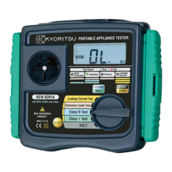
3. Product summary and explanation 3.1 Product summary The Model 6201 is a hand-held portable appliance tester, performing four functions to ensure the Safety of Class I and Class II appliances. And also can measure the mains voltage. Readings are displayed on a large liquid crystal... -
Page 7: Features
* Robust Panel and Case * Capable of measuring the voltage of main power supply * Large custom digital display * Capable of judging pass/fail of tests by LED on the panel and by buzzer. 3.4 Instrument layout (Illust: M-6201) (2) Terminal block (1) Test socket (6)LCD (7) LED for test result ... - Page 8 (1)Test socket Insert the mains plug of DUT to this socket for the polarity test of protective conductor resistance, insulation resistance and Extension leads. (2)Terminal block Connect the attached mains cord and Test Leads to this terminal block. (3)Terminal for mains cord This terminal is connected to a mains supply via M7123.
- Page 9 (11)Fuse Protected by a fuse of 600V/500mA ceramic fuse (F type Φ6.3x32mm). User can replace this fuse. (12)Mains cord(AU) M-7123 This mains cord can be connected to the mains supply so that the instrument can derive power from it. To measure contact current, the socket of the main power supply is to be equipped with an earth terminal.
-
Page 10: Explanation For Indications
3.5 Explanation for indications 3.5.1 LCD Display Insulation measurement voltage NULL indication Power supply voltage (Line-Neutral) indication Unit indication Fig.7 Note) Over range display: "OL" is displayed on the LCD. 3.5.2 LED for threshold value indication and buzzer Warning buzzer Range Status LED Color (Continuous sounds) Earth RPE < 1 Green Ω Continuity RPE ≧ 1 Ω RINS ≧ 1M Green Ω... -
Page 11: Specification
4. Specification ● General specification, measuring range and accuracy Voltage(VOLT) measurement of main power supply 207 ~ 264V AC Measuring range Resolution ± (2%rdg+3dgt) Accuracy Measurement of Protective conductor resistance(RPE) 0 ~ 19.99 Ω Measuring range 10m Ω Resolution Open-circuit voltage ±... - Page 12 Reference test condition Unless otherwise specified, this specification is dependent on following condition. (1) Ambient temperature: 23±5℃ (2) Relative humidity: 45 ~ 75% (3) Attitude: Horizontal (4) AC power supply: 240V, 50Hz (5) Altitude: 2000m or less Operating temperature and humidity range 0℃...
-
Page 13: Preparation Before A Measurement
5. Preparation before a measurement 5. 1 Visual inspection Before starting a measurement, user should undertake visual checks on the mains cord, case and that the correct type and rated fuse is fitted to the DUT. And also there should be no evidence of damage of a nature that may impair the electrical safety of the item. -
Page 14: Null Setting (Protective Conductor Resistance Range)
, and it is low value. Ω So even the resistance of Test Leads will affect the measurement result. This instrument, M-6201, can cancel the resistance of Test lead by pressing 250V/ 500V switch. The procedure of NULL setting is shown below. -
Page 15: Voltage Setting For Insulation Resistance Measurement
(3) Insert Test Lead with safety alligator clip(M-7129) in to the E terminal of the instrument, and contact the tip of the Test Lead with the metal parts of the socket on the instrument. Press start switch with contacting the Test Lead and the metal parts,the resistance of Test Lead will be displayed on the LCD as shown above fig.10 for 2sec. -
Page 16: Measuring Method
6. Measuring method 6.1 Earthed appliance Test The purpose of the test carried out for Class 1 appliances is to check the insulation resistance between accessible conductive parts and connection of protective earth and between live wire parts and accessible conductive parts is within the range defined in the standards. To conduct the tests of protective conductor resistance and insulation resistance for DUT, connect the mains plug of DUT to the test socket (1) described in clause 3.4 ... - Page 17 (3) Connect Test Lead M-7129 to Rpe terminal and clip the metal part of DUT with alligator clip. (4) Press the switch when above preparation is completed. START (5) First, measure the protective conductor resistance. Earth When it passes(1Ω or less), ○...
-
Page 18: Double Insulation Test
6.2 Double Insulation Test The Class 2 appliances have the indication of "DOUBLE INSULATION" or the symbol of . Double insulation test is to check the insulation resistance of the appliances is within the range defined in the standards. Fig.13 (1) Power on the DUT (2) Connect Test Lead M-7129 to Rpe terminal and clip the metal part of DUT with alligator clip. -
Page 19: Extension Leads Test
CAUTION ! ● When the terminal is open or the resistance value exceeds measuring range, "OL" mark (over range display) appears on the LCD. ● Do not touch the device under test while testing is in progress. Since a high voltage of 500V, user may get electrical shock. 6.3 Extension Leads Test This test is for extension leads, and check: *... - Page 20 (2) Connect the plug of the adaptor M-7140 for extension lead with the connector of the extension lead. (3) Insert the plug of extension lead into the socket on the front side of M-6201. (4) Set the range switch on M-6201 to Extension Leads Test range, and press the switch.
-
Page 21: Fuse Replacement
7. Fuse replacement When the fuse blows during use, please replace with new one according to below procedure. Fig.15 (1) Use a flat head screwdriver and turn it about 45°to left and remove the fuse cap and fuse. (2) Remove the fuse from the fuse cap and replace it with new one. (3) Install the fuse cap and fuse again. -
Page 22: Services
8. Services If this instrument should fail to operate correctly, return it to your distributor. Please remember to give all the information possible concerning the nature of the fault, as this will mean that the instrument will be serviced and returned to you more quickly. -
Page 23: Case And Strap Assembly
9. Case and strap assembly Strap belt and probe case can be attached to the instrument as below. Pass the strap belt down through the side panel of the main body from the top, and up through the slots of the probe form the bottom. (Fig. 16). Pass the strap through the buckle, adjust the strap for length and secure. - Page 24 DISTRIBUTOR Kyoritsu reserves the rights to change specifications or designs described in this manual without notice and without obligations. 92-1559 03-07...
Need help?
Do you have a question about the 6201 and is the answer not in the manual?
Questions and answers