
Related Manuals for KYORITSU 5406A


Summary of Contents for KYORITSU 5406A
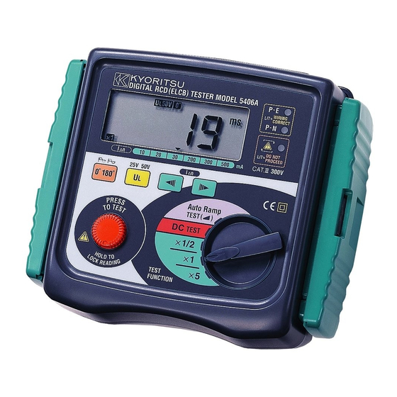
- Page 1 INSTRUCTION MANUAL DIGITAL RCD(ELCB)TESTER MODEL 5406A KYORITSU ELECTRICAL INSTRUMENTS WORKS, LTD.
-
Page 2: Table Of Contents
CONTENTS 1. Safe Testing ..................1 2. Procedure of removing cover .............. 5 2.1 Method of removing the cover ............. 5 2.2 Method of storing the cover ............5 3. Features ....................6 3.1 Instrument Layout ................6 3.2 Test Lead ..................7 3.3 Test Range (Function)... -
Page 3: Safe Testing
1. This instrument must only be used by a competent and trained person and operated in strict accordance with the instructions. KYORITSU will not accept liability for any damage or injury caused by misuse or non-compliance with the instructions or with the safety procedures. - Page 4 Failure to follow the instructions may cause injury, instrument damage and/or damage to equipment under test. Kyoritsu is by no means liable for any damage resulting from the instrument in contradiction to this cautionary note. ● Never open the instrument case - there are dangerous voltages present.
- Page 5 ● For safety reasons only use accessories (test leads, probes, cases, etc) designed to be used with this instrument and recommended by KYORITSU. The use of other accessories is prohibited as they are unlikely to have the correct safety features.
- Page 6 ○ Measurement categories(Over-voltage categories) To ensure safe operation of measuring instruments, IEC 61010 establishes safety standards for various electrical environments, categorized as O to CAT.IV, and called measurement categories. Higher-numbered categories correspond to electrical environments with greater momentary energy, so a measuring instrument designed for CAT.III environments can endure greater momentary energy than one designed for CAT.II.
-
Page 7: Procedure Of Removing Cover
2. PROCEDURE OF REMOVING COVER Model 5406A has a dedicated cover to protect against an impact from the outside and prevent the operation part, the LCD, and the connector socket from becoming dirty. The cover can be detached and put on the back side of the main body during measurement. -
Page 8: Features
3. FEATURES 3.1 Instrument Layout 6 1 2 7 3 4 5 1 ... LCD 2 ... 0°/180°SWITCH 3 ... UL VALUE SELECT SWITCH (25V/50V) 4 .... I⊿n SWITCH (up and down) 5 .... TEST BUTTON 6 .... WIRING CHECK LED ... -
Page 9: Test Lead
Barrier : provides protection against electrical shock and ensuring the minimum required air and creepage distances. 3.3 Test Range (Function) Model 5406A performs five functions. ×1/2…For testing RCD's to verify that they are not too sensitive. ×1…For measuring the trip time. -
Page 10: Applied Standards
3.5 Features Model 5406A has the follwing features: Battery is not used Model 5406A is not battery-operated, but operates by the voltage supplied from the system. Wiring check Three LEDs indicate if the wiring of the circuit under test is correct. -
Page 11: Specification
4. SPECIFICATION ● Measurement Specification Accuracy Rated Trip Current Trip Current Function voltage Settings Duration Trip current Trip Time (AC) (I ⊿ n) × 1/2 1000ms − 8% ∼− 2% 10/20/30 × 1 /200/300 1000ms /500mA +2% ∼ +8% × 5 200ms 230V+10%... - Page 12 LED indication of correct The P-E and P-N LEDs illuminate when polarity the wiring of the circuit under test is correct. The reverse LED is lit when P and N are reversed. Auto data hold The LCD reading is automatically frozen for 3 seconds after measurement.
-
Page 13: Residual Current Device (Rcd) Test
5. Residual Current Device (RCD) Test 5.1 RCD test RCD is a switching device designed for breaking currents (opening the contacts) when the residual current attains a specific given value. It works on basis of current difference between phase currents flowing to different loads and returning current flowing through neutral conductor (for a single phase installation). - Page 14 This tripping time values are concerning the RCD's correctly mounted following the manufacturer's specifications. The RCD tester Model 5406A continues driving test current until RCD trips or up to max test time. This test is named Trip test (×1 I⊿n) or Fast trip test (×5I⊿n).
- Page 15 In order to check the leakage or fault currents there are specific leakage clamp meters as Model 2432, Model 2433, Model 2413F. The RCD tester Model 5406A can test the Trip out time t⊿ and the Tripping current I⊿. ̶ 13 ̶...
- Page 16 Practical example of 3-phase + neutral RCD test in a TT system. Fig. 6 Practical example of single phase RCD test in a TN system. Fig. 7 ̶ 14 ̶...
-
Page 17: Rcd Test On "Old Tt System
WARNING Do not press the "Test button" if the voltmeter reads a value of 220V. R CD 220V 220V 220V Connecting the model 5406A to this system, all three wiring check LEDs should be lit. Fig. 8 ̶ 15 ̶... -
Page 18: Test Procedure
Do not use this instrument to check the correct wiring of the power supply. Kyoritsu will not be held liable for any accident that may result from incorrect wiring of the power supply line. -
Page 19: Testing
6.3. TESTING (1) Set the TEST FUNCTION ・NO TRIP TEST....×1/2 : Max time 1000ms ・TRIP TEST.....×1 : Max time 1000ms ・FAST TRIP TEST..×5 : Max time 200ms ・DC TEST......DC TEST : Max time 1000ms ・AUTO RAMP TEST..Auto Ramp TEST ( ... - Page 20 Note : ● If the RCD does not trip, the tester will supply the test current for a maximum of 1000ms on the X1/2 and X1 ranges. The fact that the RCD has not tripped will be evident because the P-N and P-E LEDs will still be on.
- Page 21 BLACK GREEN PHASE NEUTRAL EARTH Test Lead Model 7121B (Optional Accessory) Fig. 10 WARNING Take enough caution not to make faulty wiring when using Model7121B. Especially, be careful not to connect it to phase- phase. CAUTION Keep your fingers and hands behind the barrier during a measurement.
-
Page 22: Servicing
7. SERVICING If this tester should fail to operate correctly, return it to your distributor stating the exact nature of the fault. Please remember to give all the information possible concerning the nature of the fault, as this will mean that the instrument will be serviced and returned to you more quickly. -
Page 23: Case And Strap Belt Assembly
8. CASE AND STRAP BELT ASSEMBLY Correct assembly is shown in Fig 11. By hanging the instrument round the neck, both hands will be left free for testing. Pass the strap belt down through the side panel of the main body from the top, and up through the slots of the probe case from the bottom. - Page 24 DISTRIBUTOR 92-1490B 10-16 Kyoritsu reserves the rights to change specifications or designs described in this manual without notice and without obligations.
Need help?
Do you have a question about the 5406A and is the answer not in the manual?
Questions and answers