
Related Manuals for KYORITSU 3321A


Summary of Contents for KYORITSU 3321A
-
Page 1: Instruction Manual
Instruction manual Compact Insulation resistance tester with 3-range KEW MEG series MODEL3321A, 3322A, 3323A KYORITSU ELECTRICAL INSTRUMENTS WORKS,LTD. -
Page 2: Table Of Contents
Contents 1.Safety warnings ……………………………………………………1 2.Features ……………………………………………………………3 3.Specification ………………………………………………………4 4.Instrument layout …………………………………………………8 5.Preparation for measurement 5−1 Mechanical zero adjustment ………………………………9 5−2 Test lead connection ………………………………………9 5−3 Battery voltage check ………………………………………10 5−4 Power-on-indication LED …………………………………10 6.Measurement 6−1 AC voltage measurement …………………………………10 (Mains disconnection check) 6−2 Insulation resistance measurement ………………………12 6−3 Continuous measurement …………………………………14 6−4 Output voltage characteristics ……………………………14... -
Page 3: Safety Warnings
1.Safety warnings ○ This instrument has been designed, manufactured and tested according to IEC 61010-1: Safety requirements for Electronic Measuring apparatus, and delivered in the best condition after passed the inspection. This instruction manual contains warnings and safety rules which must be observed by the user to ensure safe operation of the instrument and retain it in safe condition. - Page 4 ¡ Never rotate the Range switch with the test leads connected to the equipment under test. ¡ Do not install substitute parts or make any modification to the instrument. Return the instrument to your local KYORITSU distributor for repair or re-calibration in case of suspected faulty operation.
-
Page 5: Features
2.Features MODEL3321A/ 3322A/ 3323A are three-range insulation resistance testers for testing low-voltage installation below 600V. ¡ Designed to following safety standards: IEC 61010-1, IEC 61010-031, IEC 61557 ¡ Small and light weight. ¡ Auto-discharge function When insulation resistance like a capacitive load is measured, electric charges stored in capacitive circuits are automatically discharged after measuring. -
Page 6: Specification
3.Specification ¡ Applicable standards IEC 61557 IEC 61010-1 Measurement CAT.III 600V Pollution degree2 Protection class II Location for use: altitude 2000m or less IEC 61010-031 IEC 60529 IP40 ¡ Measuring range and accuracy <Insulation resistance range> MODEL3321A Nominal voltage 250V 500V 1000V Max. - Page 7 MODEL3323A Nominal voltage 100V Max. effective scale value 10MΩ 10MΩ 20MΩ Mid-scale value 0.2MΩ 0.2MΩ 0.5MΩ Accuracy in primary 0.01∼5MΩ 0.01∼5MΩ 0.02∼10MΩ effective measuring ranges within ±5% of indicated value Accuracy in primary Measuring ranges other than above, 0 and ∞. effective measuring ranges within ±10% of indicated value Accuracy at 0 and ∞...
- Page 8 <AC voltage range> Measured voltage 0∼600V within ±3% of max scale value ( ACV range ) Accuracy within ±5% of max scale value ( Others ) <Number of measurement> Possible number of measurement within the "BATTERY.GOOD" range.(Measure 5 sec., and take pause for 25 sec.) Resister Possible number Range...
- Page 9 ¡ Overload protection The instrument operates properly after each of the voltage shown in the table below is applied for 10 sec. MODEL 3321A 3322A 3323A All ranges : Insulation 1000V range : AC 1200V All ranges : resistance The other ranges : AC 600V...
-
Page 10: Instrument Layout
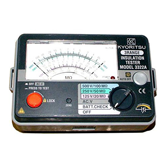
4.Instrument layout Fig. 1 Instrument layout ①Meter zero adjuster ②Test button ③Scale plate ④Pointer ⑤Insulation resistance scale ⑥AC voltage scale ⑦"BATTERY-GOOD" range ⑧Power-on-indication LED ⑨Guard terminal ⑩Probe socket ⑪Backlight switch ⑫Range switch ⑬Test lead with remote control switch (MODEL7103) ⑭Remote control switch ⑮Line probe ⑯Earth cord ⑰Standard prod (MODEL8072) -
Page 11: Preparation For Measurement
5.Preparation for measurement 5−1 Mechanical zero adjustment With the Range switch set to the OFF position and without pressing the Test button, turn the Zero adjuster with a screwdriver so that the pointer lines up with the "∞" mark on an insulation resistance scale. -
Page 12: 5−3 Battery Voltage Check
5−3 Battery voltage check (1) Set the Range switch to the BATT. CHECK position. (2) Press the Test button or Remote control switch. (3) If the meter pointer does not move to BATT GOOD, replace the batteries as shown in Section 7 "Battery replacement". Batteries have exhausted. -
Page 13: Mains Disconnection Check
CAUTION Never press CAUTION remote switcth Never press test button AC voltage measurement (Mains disconnection check) The AC voltage measurement function is available on any ranges. DANGER ¡ Never make measurement on a circuit in which the electrical potential exceeds AC/DC600V in order to avoid possible shock hazard. -
Page 14: 6−2 Insulation Resistance Measurement
6−2 Insulation resistance measurement Before performing any insulation test, check the maximum voltage that may be applied to the circuit under test. Note: ¡ Some circuits have an unstable insulation resistance, which causes the reading to vary during measurement. ¡ The instrument may generate a high pitch tone during measurement. - Page 15 (2) Connect Earth probe to the earth terminal of the circuit under test. If the circuit is not earthed, connect Earth probe to any appropriate conductor. (3) Connect Line probe to the circuit under test and press the Test button or Remote control switch. (4) Take the reading on the scale for the selected insulation resistance range.
-
Page 16: 6−3 Continuous Measurement
<Auto discharge function> This function allows electric charges stored in the capacitance of the circuit under test to be automatically discharged after testing.Discharge can be monitored by the AC voltage reading. (6) Set the Range switch to the OFF position, and disconnect the probes from the instrument. - Page 17 range range range Insulation Resistance[MΩ] range range range Insulation Resistance[MΩ] range range range Insulation Resistance[MΩ] ― 15 ―...
-
Page 18: 6−5 Using Guard Terminal (Only For Model3321A)
6−5 Using Guard Terminal (only for MODEL3321A) Shown below is an example of the insulation resistance measurement of an electric wire. If Line probe is simply connected to the wire conductor and Earth probe to the woven metal shield as shown, a measurement error will be introduced as this results in the measurement of the combined resistance of insulation resistance and the surface leakage resistance at the cut end of the electric wire. -
Page 19: Battery Replacement
7.Battery replacement DANGER Never open the Battery cover during a measurement. WARNING To avoid possible electric shock, remove test leads before opening the Battery cover. After replacing batteries, be sure to tighten up the screws for Battery cover. CAUTION Do not mix new and old batteries. Install batteries in correct polarity as marked inside the Battery compartment. -
Page 20: Notes On Housing Case And Accessories 8−1 Case Lid
8.Notes on Housing case and accessories 8−1 Case lid Case lid can be fit under the Housing case while making measurement. (1) Unhook and open the Case lid. (2) Turn it 180 degrees. (3) Put the Case lid under the Housing case. (4) Hook it on to the Housing case. -
Page 21: 8−3 Test Prods And Replacement
8−3 Test prods and replacement 1. Types of Test prods MODEL8072:Standard Test prod Used for ordinary measurement. (Attached to the Line probe at the time of purchase.) MODEL8017:Extension probe Used in difficult-to-reach situations. MODEL8016:Pickle prod (Optional) Used to hook the probe on a conductor. 2. -
Page 22: 8−4 Adaptors For The Earth Cord And Replacement
8−4 Adaptors for the Earth cord and replacement 1. Adaptors MODEL7131:Safety alligator clip Connected to the Earth terminal of the Earth terminal board. MODEL7101:Flat test bar Connected to the earth side of the outlet. 2. How to replace Adaptors To remove the adaptors, pull them out. Then firmly attach the adaptor as desired to the tip of the Earth cord. -
Page 23: 8−5 Cleaning Meter Cover
8−5 Cleaning Meter cover This instrument is managed by our company's quality standard and is delivered in the best condition after passed the inspection. But in the dry time of winter static electricity sometimes builds up on the meter cover due to the characteristic of plastic. - Page 24 DISTRIBUTOR 08-07 92-1646A...
Need help?
Do you have a question about the 3321A and is the answer not in the manual?
Questions and answers