
Related Manuals for KYORITSU 3132A


Summary of Contents for KYORITSU 3132A
- Page 1 INSTRUCTION MANUAL ANALOGUE INSULATION-CONTINUITY TESTER MODEL 3132A KYORITSU ELECTRICAL INSTRUMENTS WORKS, LTD.
-
Page 2: Table Of Contents
CONTENTS 1.Safety Precautions …………………………………………………………… 1 2.Features ……………………………………………………………………… 4 3.Specifications ………………………………………………………………… 5 4.Instrument Layout …………………………………………………………… 8 5.Preparation for Testing ……………………………………………………… 9 5-1 Mechanical Zero Adjustment …………………………………………… 9 5-2 Battery Voltage Check ………………………………………………… 9 5-3 Test Probe Connection ………………………………………………… 9 5-4Test Probe check ………………………………………………………… 9 6.Operation ……………………………………………………………………... -
Page 3: Safety Precautions
● The instrument must only be used by a competent trained person and operated in strict accordance with the instructions. KYORITSU will not accept any liability for any damage or injury caused by misuse or non- compliance with the instructions or safety procedures. - Page 4 ● Do not install substitute parts or perform any unauthorized modification of the instrument. Return the instrument to Kyoritsu or your distributor for service and repair to ensure the safety features are maintained. ● Do not replace batteries when the surface of the instrument is wet.
- Page 5 CAUTION ● Always make sure to set the range switch to the appropriate position before making measurements. ● Do not expose the instrument to the direct sun, dew fall or extreme temperature and humidity. ● When the instrument will not be in use for a long period of time, place it in storage after removing batteries.
-
Page 6: Features
2.Features MODEL-3132A is an analogue tester with five ranges for insulation resistance measurement and continuity testing (resistance tests) of low voltage installations. ● Designed to safety standards: IEC 61557-1 (General requirements for measuring equipment for low voltage distribution systems) IEC 61557-2 (Equipment for insulation resistance measurement for low... -
Page 7: Specifications
3.Specifications ● Measuring Range and Accuracy (at 23±5°C, relative humidity 45-75%) ○ Insulation Resistance Ranges:(IEC 61557-2) Normal output 250V 500V 1000V Voltage Measuring Ranges 0 - 100MΩ 0 - 200MΩ 0 - 400MΩ Open -Circuit Rated test voltage +20%, -0% Voltage Normal current 1mA DC +20%, -0%... - Page 8 Continuity Test (Resistance Test) Ranges(IEC 61557-4) Ranges Measuring range to keep Maximum percentage operating error operating error 3 Ω 0.2Ω - 3Ω ±30% The influencing variations used for calculating the operating error are denoted as follows: 。 。 Temperature C and 35 Supply voltage : 6.4V to 10.4V 。...
- Page 9 ● Storage Temperature & Humidity: -10 - 50°C, relative humidity up to 75% ● Insulation Resistance : More than 50MΩ at 1000V DC between electrical circuit and housing case ● Withstand Voltage: 5550V AC for one minute between electrical circuit and housing case ●...
-
Page 10: Instrument Layout
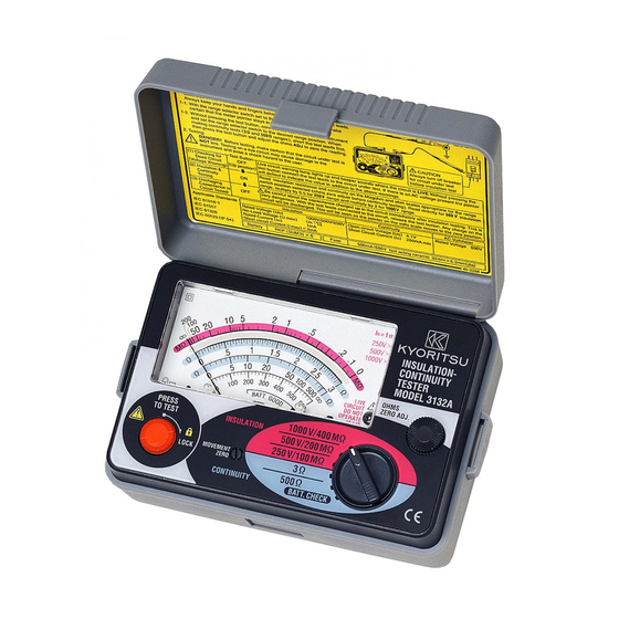
4.Instrument Layout ⑫ ⑪ ⑩ ③ ④ ⑤ ⑧ ⑨ ⑥ ② ① ⑦ ①METER MOVEMENT ZERO ADJUST ②TEST BUTTON ③SCALE PLATE ④INPUT CONNECTOR ⑤LIVE CIRCUIT LAMP ⑥OHMS ZERO ADJUST ⑦RANGE SELECTOR SWITCH ⑧TEST PROBE (RED) LINE PROBE ⑨TEST PROBE (BLACK) EARTH PROBE ⑩TEST PROBE CAP(RED) ⑪TEST PROBE CAP(BLACK) ⑫ALLIGATOR CLIP(BLACK) -
Page 11: Preparation For Testing
5.Preparation for Testing 5-1 Mechanical Zero Adjustment Check that the pointer lines up with the middle of the mark on the scale correctly. If not, adjust it by rotating the meter movement zero adjust with a screwdriver, etc. 5-2 Battery Voltage Check ①... -
Page 12: Operation
Operation 6-1 AC Voltage Warning Function DANGER ● Never make measurements with the battery compartment cover removed. CAUTION ● Never press the test button if the live circuit warning lamp is lit or the warning buzzer sounds. This may damage the circuit. Voltage check can be made with the range selector switch at any position. -
Page 13: Insulation Resistance Measurement
6-2 Insulation Resistance Measurement DANGER ● Always test the circuit or equipment to ensure it is surely de-energized before measurement according to the instruction of 6-1. ● To avoid electrical shock, measurements must be performed on de- energized circuits only. ●... - Page 14 ④ Check the circuit under test is not energized as follows. Connect the test probe to the circuit under test and read a voltage value. If the circuit is live, the meter indicates the voltage, the live circuit lamp is lit, and warning buzzer sounds.
-
Page 15: Continuity Testing (Resistance Tests)
required test voltage when providing a steady state current of 1mA. The minimum allowable resistance level is 0.25MΩ for the 250V test, 0.5MΩ for the 500V test and 1MΩ for the 1000V test. ● Principle of Insulation Resistance Measurement Resistance value can be obtained by applying a certain high voltage to the resistance (insulation resistance) and measuring the flowing current. - Page 16 CAUTION ● Never press the test button if the live circuit warning lamp is lit or the warning buzzer sounds. This may damage the circuit. ● In case that an additional operating circuit is connected in parallel to the circuit under measurement, the measurement error might be caused due to the effects of impedance of the circuit connected in parallel or transient current.
-
Page 17: Battery & Fuse Replacement
Battery & Fuse Replacement DANGER ● Never open the battery compartment cover while making measurement. To avoid possible electrical shock, disconnect the test probe before opening the cover for battery and fuse replacement. ● Replacement fuse must be have the following rating. Fast acting type, F 500mA/600V, φ... -
Page 18: Notes On Accessories
8.Notes on Accessories 8-1 Case Lid The case can be fitted under the housing case as illustrated bellow. ① Open the case lid as shown. ② Turn it 180 degrees. ③ Put the case lid under ④Hook it on the housing case. the housing case. -
Page 19: Cleaning Of The Instrument
9.Cleaning of the Instrument ◎ Cleaning the meter cover This tester is managed by our company's quality standard and is delivered in the best condition after passed the inspection. But in the dry time of winter static electricity sometimes builds up on the meter cover due to the characteristic of plastic. - Page 20 DISTRIBUTOR Kyoritsu reserves the rights to change specifications or designs described in this manual without notice and without obligations. KYORITSU ELECTRICAL INSTRUMENTS WORKS, LTD. 92-1493A 03-08...
Need help?
Do you have a question about the 3132A and is the answer not in the manual?
Questions and answers