Table of Contents
Advertisement
Advertisement
Table of Contents

Related Manuals for KYORITSU KEW 4105A


Summary of Contents for KYORITSU KEW 4105A
-
Page 2: Table Of Contents
CONTENTS 1. Safety Precautions ..................1 2. Features ..................... 5 3. Specifications ..................... 6 4. Layout Diagram ..................9 5. Preparation for Measurement ..............10 5-1 Battery Voltage Check ............... 10 5-2 Connecting Test Probes ..............10 6. Operating Instructions ................10 6-1 Principle of Measurement .............. -
Page 3: Safety Precautions
Be sure to observe the above rules strictly. Not following the instructions may cause injury or instrument damage. Kyoritsu is by no means liable for any damage resulting from the instrument in contradiction to these cautionary notes. ○ The symbol on the instrument means that the user must refer to the manual for safe operation of the instrument. - Page 4 ● Do not install substitute parts or make any decomposition or modification to the instrument. Return the instrument to Kyoritsu or your distributor for repair or re-calibration. ● Do not replace batteries when the surface of the instrument is wet.
- Page 5 CAUTION ● Make sure that the test probe are securely connected to the terminal of the instrument. ● Be sure to set the range selector switch to the OFF position after use. When the instrument will not be in use for a long period of time, place it in storage after removing the batteries.
- Page 6 Measurement Category To ensure safe operation of measuring instruments, IEC 61010 establishes safety standards for various electrical environments, categorized as O to CAT IV, and called measurement categories. Higher-numbered categories correspond to electrical environments with greater momentary energy, so a measuring instrument designed for CAT III environments can endure greater momentary energy than one designed for CAT II.
-
Page 7: Features
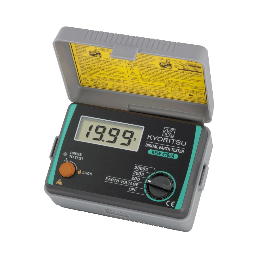
2. Features KEW 4105A is an earth resistance tester for testing power distribution lines, in-house wiring system, electrical appliances etc. It also has an earth voltage range for earth voltage measurement. ○ Designed to safety standard IEC 61557. ○ Dust and drip proof construction in conformity with IEC 60529 (IP54). -
Page 8: Specifications
̶ 6 ̶... - Page 9 ̶ 7 ̶...
- Page 10 ̶ 8 ̶...
-
Page 11: Layout Diagram
̶ 9 ̶... -
Page 12: Preparation For Measurement
Alligator clip Flat test bar ※1 Barrier ※1 Barrier *1 Barrier is a part providing protection against electrical shock and ensuring the minimum required air and creepage distances. ̶ 10 ̶... -
Page 13: Precise Measurement
̶ 11 ̶... -
Page 14: Simplified Measurement
̶ 12 ̶... - Page 15 ̶ 13 ̶...
- Page 16 ② Earth Voltage Measurement Set the range switch to EARTH VOLTAGE position in the condition of ①. Earth voltage will be indicated on the display. Make sure that the voltage is 3 V or less. When the display reads more than 3 V, it may result in excessive errors in earth resistance measurement.
-
Page 17: Battery Replacement
7. Battery Replacement DANGER ● Never attempt to open the battery compartment cover, if the outer surface of the instrument is wet. ● Never attempt to replace batteries while making measurement. To avoid shock hazard, turn the instrument off and disconnect the test leads and the probes from the instrument before opening the battery compartment cover. -
Page 18: Notes On Housing Case & Accessories
8. Notes on Housing Case & Accessories 8-1 Case Lid Case lid can be fit under the housing case while making measurement. 8-2 How to Fit Strap Belt The instrument is equipped with a strap belt to suspend from the neck to allow both hands to be used freely for easy and safe operation ̶... -
Page 19: Cautions When Using Test Leads
9. Cautions when using Test Leads Do not connect the Precision Measurement Test Leads where electrical potentials exceeding 33Vrms with peak value of 46V or DC70V. Please use the Simplified Measurement Test Leads for voltage measure- ments. The Alligator clips need to be attached and used under CAT. III/ IV test environments and the Flat Test Bars are under CAT. -
Page 20: Before Sending For Service
10. Before Sending for Service If this instrument should fail to operate correctly, return it to your nearest distributor stating the exact nature of the fault. Before returning the instrument follow the trouble-shooting guide shown below. ● If the instrument does not turn on; Check whether batteries are missing or they are installed incorrect polarity. -
Page 21: Service
11. Service If this instrument should fail to operate correctly, return to your nearest distributors stating the exact nature of the fault. ̶ 19 ̶... - Page 22 MEMO ̶ 20 ̶...
- Page 24 3-17 92-2251A...
Need help?
Do you have a question about the KEW 4105A and is the answer not in the manual?
Questions and answers
My earth tester were loos manual book.
The manual for the KYORITSU KEW 4105A earth tester is the "KEW 4105A Instruction Manual," available in English and Spanish.
This answer is automatically generated