Table of Contents
Advertisement
Advertisement
Table of Contents

Subscribe to Our Youtube Channel
Related Manuals for KYORITSU KEW6201A


Summary of Contents for KYORITSU KEW6201A
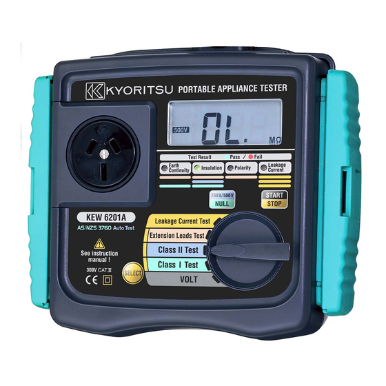
- Page 1 INSTRUCTION MANUAL PORTABLE APPLIANCE TESTER KEW6201A...
-
Page 2: Table Of Contents
CONTENTS 1. Safe testing ………………………………………………………………………………………1 2. Procedure of removing cover ……………………………………………………………. 3 2.1 Method of removing the cover ……………………………………………………. 3 2.2 Method of storing the cover ………………………………………………………. 3 3. Product summary and explanation ……………………………………………………. 4 3.1 Product summary …………………………………………………………………….. 4 3.2 Test range …………………………………………………………………………………... -
Page 3: Safe Testing
This instrument must only be used by a competent and trained person and operated in strict accordance with the instructions. KYORITSU will not accept liability for any damage or injury caused by misuse or non-compliance with the instructions or with the safety procedures. - Page 4 • It is essential that the above instructions are adhered to. Failure to follow the above instructions may cause injury, instrument damage and/or damage to equipment under test. Kyoritsu is by no means liable for any damage resulting from the instrument in contradiction to these cautionary notes.
-
Page 5: Procedure Of Removing Cover
# CAUTION • When using Test Leads with alligator clip, be sure to check the alligator clip is firmly connected to the metal part of the device under test. Otherwise, inaccurate measurement or arc at the contacts may occurs. • The rated measuring voltage for insulation test is 500V.DC. For electrical devices to be tested, if this test voltage seems not proper to apply, contact your distributor and ask for advices. -
Page 6: Product Summary And Explanation
These are often described as earthed appliances. Class II: Appliances which have both functional and additional insulation where any metal parts cannot become “Live” under fault conditions. 3.2 Test Function KEW6201A have following features. Function Tests of contents Class I Test •Protective conductor resistance •Insulation (250V or 500V) -
Page 7: Features
3.3 Features • Warning for the appliance to be ON. • Selection for 250V or 500V on the insulation resistance test. • Null function for the protective conductor resistance test. • Warning for the over range value in the LCD. •... - Page 8 ⑵ Terminal block Connect the attached mains cord and Test Leads to this terminal block. ⑶ Terminal for mains cord This terminal is connected to a mains supply via M7123. ⑷ Terminal for Extension leads adaptor It corresponds to L, N, E of test socket, and the extension leads adaptor (M-7140) connected with the cord reel to be plugged to it.
- Page 9 ⑿ Fuse Protected by a fuse of 600V/10A ceramic fuse (F type Φ6.3x32mm). User can replace this fuse. Please refer to Section 7 for information on replacement fuse. ⒀ Mains cord (AU) M-7123 This mains cord can be connected to the mains supply so that the instrument can derive power from it.
-
Page 10: Explanation For Indications
3.5 Explanation for indications LCD Display Null indication Power supply voltage Over temperature warning (Line-Neutral) indication Unit indication Fig. 7 Insulation measurement voltage Note) Over range display: “OL” is displayed on the LCD. Display symbols DUT is OFF. Represents LN-E. When leakage current R e p r e s e n t s l e a k a g e test is interrupted. -
Page 11: Specification
4. Specification 4.1 General specification, measuring range and accuracy Voltage(VOLT) measurement of main power supply Measuring range 207 ~ 264V AC Resolution Accuracy ± (2%rdg+3dgt) Measurement of Protective conductor resistance(RPE) Measuring range 0 ~ 15.00Ω Resolution 10mΩ Open-circuit voltage <AC12V Measuring current 10A AC nominal value Accuracy... -
Page 12: Reference Test Condition
4.3 Reference test condition Unless otherwise specified, this specification is dependent on following condition. ⑴ Ambient temperature: 23±5˚C ⑵ Relative humidity: 45 ~ 75% ⑶ Attitude: Horizontal ⑷ AC power supply: 240V, 50Hz ⑸ Altitude: 2000m or less Operating temperature and humidity range 0℃... -
Page 13: Preparation Before A Measurement
5. Preparation before a measurement 5.1 Visual inspection Before starting a measurement, user should undertake visual checks on the mains cord, case and that the correct type and rated fuse is fitted to the DUT. And also there should be no evidence of damage of a nature that may impair the electrical safety of the item. -
Page 14: Null Setting (Protective Conductor Resistance Function)
# WARNING • When the voltage of main power supply is 265V or more, “HI-V” is displayed on the LCD. • In that case, disconnect the mains cord of the instrument from main power supply. 5.2.3 Null setting A criteria of judgment for Earth Continuity is 1Ω, and it is low value. So even the resistance of Test Leads will affect the measurement result. -
Page 15: Voltage Setting For Insulation Resistance Measurement
Press Null|250V/500V switch with contacting the Test Lead and the metal parts, the resistance of Test Lead will be displayed on the LCD as shown above fig.10 for 2sec. Then, the instrument cancels the resistance value of Test Lead and adjust the displayed value to “0.00”... -
Page 16: Measuring Method
6. Measuring method 6.1 Class I Test The purpose of the test carried out for Class I appliances is to check the insulation resistance between accessible conductive parts and connection of protective earth and between live wire parts and accessible conductive parts is within the range defined in the standards. - Page 17 Class I Test Flowchart Start ⑴. Protective conductor resistance. RPE < = 1Ω? Light up in red “no” → “Con” → “value” will be repeated on the LCD. Light up in green ⑵.Appliance switch test When the resistance between LN is about 100kΩ or more Is the Switch “no”...
-
Page 18: Class I Test (Select The Leakage Current Test)
6.2 Class I Test (Select the Leakage current test) Selecting “Class I test” while Select Switch is being pressed down initiates Leakage current test instead of Insulation resistance test. In case of selecting Leakage current test, metal parts other than the heating or movable parts must be clipped with Test Lead M-7129A since the DUT activates. -
Page 19: Class Ii Test
# CAUTION • When the terminal is open or the resistance value exceeds measuring range, “OL” mark (over range display) appears on the LCD. • The test will stop. A message “Stp” appears on the LCD but values of Leakage current aren't displayed. # WARNING •... -
Page 20: Class Ii Test (Select The Leakage Current Test)
Class II Test Flowchart Start (1). Appliance switch test When the resistance between LN is about 100kΩ or more Is the Switch turning on? “no” → “OFF” is displayed alternately on the LCD. Light up in green (2). Insulation resistance between L/N and PE. LnE >... - Page 21 Class II Test (Select the Leakage current test) Flowchart Start Power on Leakage current test. Brief indications “ S-” and “on” will be displayed 5sec in turns on the LCD for 5 sec and prompt the user to set the DUT switch on. Then a mark indicating working DUT function will be displayed for 10 sec.
-
Page 22: Extension Leads Test
6.5 Extension Leads Test • This test is for extension leads, and check: • Protective conductor resistance between accessible conductive parts and connection of protective earth. • Insulation resistance between L/N and PE. • Polarity check of the Line and Neutral terminal of plug and socket. Test procedure and the connection are as follows. - Page 23 Extension Leads Test Flowchart Start (1). Protective conductor resistance test. RPE < = 1Ω? Light up in red “no” → “Con” → “value” will be repeated on the LCD. Light up in green (2). Insulation resistance test between L/N and PE. LnE >...
- Page 24 • When the function is set to extension leads test while pressing Select switch, Power on leakage current test will be carried out instead of Insulation resistance test. ・ Protective conductor resistance between accessible conductive parts and connection of protective earth. ...
-
Page 25: Leakage Current Test
# WARNING • Operate a device and measure the leakage current flowing on it at Leakage current test function. Care should be taken not to touch with the heating or movable parts during tests. Extra care should also be taken to light and heat generated by the device. •... -
Page 26: Fuse Replacement
# WARNING • Operate a device and measure the leakage current flowing on it at Leakage current test function. Care should be taken not to touch with the heating or movable parts during tests. Extra care should also be taken to light and heat generated by the device. •... -
Page 27: Services
# WARNING • Be sure to remove mains cord from the instrument before replacing fuse. • The fuse that user can replace is this fuse only. Never attempt to perform the other repairing. # CAUTION • Please use the specified fuse (Fast acting type ceramic fuse: 600V/10A - Φ6.3x32mm). - Page 28 DISTRIBUTOR Kyoritsu reserves the rights to change specifications or designs described in this manual without notice and without obligations. 92-1843E 9-14...
Need help?
Do you have a question about the KEW6201A and is the answer not in the manual?
Questions and answers