Do you have a question about the KEW 3022 and is the answer not in the manual?
Questions and answers
大西
June 16, 2025
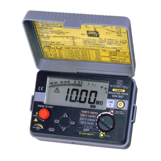
LIVE LEDとは
1 comments:
Mr. Anderson
August 19, 2025
For the KYORITSU KEW 3022, the LIVE LED indicates the presence of stored electric charge or voltage in the circuit under test. It flickers while the circuit is discharging after testing. Users should not touch the circuit until the LIVE LED and LIVE circuit warning stop flickering to avoid electric shock.


Need help?
Do you have a question about the KEW 3022 and is the answer not in the manual?
Questions and answers
LIVE LEDとは
For the KYORITSU KEW 3022, the LIVE LED indicates the presence of stored electric charge or voltage in the circuit under test. It flickers while the circuit is discharging after testing. Users should not touch the circuit until the LIVE LED and LIVE circuit warning stop flickering to avoid electric shock.
This answer is automatically generated