Table of Contents
Advertisement
Quick Links
Advertisement
Table of Contents

Subscribe to Our Youtube Channel
Related Manuals for KYORITSU kew 4300


Summary of Contents for KYORITSU kew 4300
- Page 1 Instruction Manual Simplified Earth Tester KEW 4300...
-
Page 2: Table Of Contents
Contents 1. Safety warnings ・・・・・・・・・・・・・・・・・・・・・・・・・・・・・・・・・・・・・・・・・ 1 2. Features ・・・・・・・・・・・・・・・・・・・・・・・・・・・・・・・・・・・・・・・・・・・・・・・ 4 3. Specification ・・・・・・・・・・・・・・・・・・・・・・・・・・・・・・・・・・・・・・・・・・・・ 5 4. Instrument layout ・・・・・・・・・・・・・・・・・・・・・・・・・・・・・・・・・・・・・・・・ 8 5. Accessories ・・・・・・・・・・・・・・・・・・・・・・・・・・・・・・・・・・・・・・・・・・・・ 10 6. Getting started ・・・・・・・・・・・・・・・・・・・・・・・・・・・・・・・・・・・・・・・・・ 11 6-1 Battery voltage check ・・・・・・・・・・・・・・・・・・・・・・・・・・・・・・・ 11 6-2 Attaching Metal tip/ adapter ・・・・・・・・・・・・・・・・・・・・・・・・・・ 11 7. -
Page 3: Safety Warnings
1. Safety warnings This instrument has been designed, manufactured and tested according to IEC 61010-1: Safety requirements for Electronic measuring apparatus, and delivered in the best condition after passing quality control tests. This instruction manual contains warnings and safety rules which have to be observed by the user to ensure safe operation of the instrument and to maintain it in safe condition. - Page 4 ● Do not press the Test button when connecting the test leads to the instrument. ● Do not install substitute parts or make any modification to the instrument. Return the instrument to your local Kyoritsu distributor for repair or re-calibration in case of suspected faulty operation.
- Page 5 Symbols Primary electrical circuits of the equipment connected CAT.III directly to the distribution panel, and feeders from the distribution panel to outlets. Instrument with double or reinforced insulation User must refer to the explanations in the instruction manual. (Functional) Earth terminal Crossed-out wheel bin symbol (according to WEEE Directive: 2002/96/EC) indicating that this electrical...
-
Page 6: Features
2. Features KEW4300 is a simplified earth resistance tester (based on 2-pole method) that can be used for various distribution lines and electrical appliances and it also can measure AC/DC voltages. (As for AC voltages, true rms values can be obtained.) ●... -
Page 7: Specification
3. Specification ● Measurement range and accuracy (23ºC±5Cº, relative humidity 75% or less) Voltage/ Earth voltage measurement Measurement range Display range Accuracy AC5.0 to 300.0V (45 to 65Hz) 0.0 to 314.9V ±1%rdg±4dgt (425V peak or less) DC±5.0 to ±300.0V 0.0 to ±314.9V ±1%rdg±8dgt *AC measurement method : rms detection For the waveforms other than sinewave... - Page 8 ● Applicable ● IEC 61010-1 standards ● IEC 60529(IP40) ● IEC 61557-1, -5 ● IEC 61326-1, 2-2 ● IEC 61010-031 MODEL7248 / CAT.III600V (Alligator clip should be attached and used in the CAT. III or higher environment.) MODEL8253 / CAT.III300V (while it is connected to the instrument) * When the test leads are connected to the instrument, the lower category either of...
- Page 9 ● Operating Error Operating error (B) is an error obtained within the rated operating conditions, and calculated with the intrinsic error (A), which is an error of the instrument used, and the error (Ei) due to variations. According to IEC61557, the maximum operating error should be within ±30%.
-
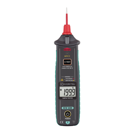
Page 10: Instrument Layout
4. Instrument layout (1) Instrument Body Fig. 4-1 Name Details To connect the replaceable metal tip MODEL8072 1 H+S(C+P) terminal has been installed and delivered. To illuminate the measurement spots 2 LED light The light turns on/off automatically in relation to ambient brightness. - Page 11 (2) LCD Fig. 4-2 ● Symbols displayed on the LCD Indicate the batteries need to replace. Show the measured results. Appear when the measured result exceeds the display range. Resistance : >2099Ω Voltage : > 314.9V (“-OL” for negative DC voltages) Indicate the end of a measurement with frozen measured result.
-
Page 12: Accessories
5. Accessories ● Test leads (1) MODEL7248 – with Alligator clip and Flat test bar (2) Banana plug, both ends, black L-shaped Banana plug + Fig. 5-1 (3) Alligator clip (4) Flat test bar + Fig. 5-2 Fig. 5-3 ●... -
Page 13: Getting Started
6. Getting started 6-1 Battery voltage check (1) Please refer to “10. Replacing batteries” in this manual and insert batteries in KEW4300. (2) Hold down the Power button at least 1 sec and power on KEW4300. * A long press of 1 sec or longer is required to power on/ off the instrument. - Page 14 [How to replace the parts] Detach the metal tip by turning the red plastic parts counter clockwise. Install the metal tip you want to use into the hexagon hole, and turn the red plastic parts clockwise to tighten firmly. MODEL 8072 MODEL 8253 Hexagon 六角穴...
-
Page 15: Voltage Measurement
7. Voltage measurement # DANGER ● Never apply voltages exceeding 300V, max over-voltage protection, to this instrument. 7-1 Measurement procedure (1) Connect the test leads to the instrument. Plug the L-shaped Banana plug of MODEL7248 into the E terminal as illustrated below. Fig. -
Page 16: Live Circuit Warning
(3) The measured voltage is displayed on the LCD. Take the reading without pressing the Test button. The instrument judges DC or AC and shows “DC” or “AC” sign on the LCD. * When negative DC voltages are detected at the H+S(C+P) terminal, the negative polarity sign “-“... -
Page 17: Earth Resistance Measurement
8. Earth resistance measurement This instrument can measure the earth resistances of distribution line, internal wiring and electrical appliance. # DANGER ● Never apply inputs exceeding 300V between the measuring terminals at earth voltage measurements. ● No voltage should be applied between the measuring terminals during earth resistance measurements. -
Page 18: Measurement Procedure
8-2 Measurement procedure (1) Connect the test leads to the instrument. Plug the L-shaped Banana plug of MODEL7248 into the E terminal as illustrated below. Fig. 8-2 (2) Connection Connect the instrument as illustrated below. POWER H+S(C+P) LOAD Fig. 8-3 Measuring the earth resistance Fig. - Page 19 ● The displayed value should be less than 10V. The warning LED starts blinking yellow when the earth voltage is 10V or higher. (The LED starts blinking at 3V or higher if the frequency of the earth voltage is 400Hz.) LED starts blinking.
-
Page 20: Lcd Backlight And Led Light
9. LCD backlight and LED light The LCD backlight and the LED light on this instrument turn on/off automatically in relation to ambient brightness. These lights keep on for about 15 sec once they turn on. The Ambient light sensor as shown in the below figure senses the ambient brightness. -
Page 21: Replacing Batteries
10. Replacing batteries When the Battery symbol appears on the LCD, replace the batteries with new ones. # DANGER ● Never open the Battery compartment cover if the instrument is wet. ● Do not attempt to replace batteries during a measurement. In order to avoid getting an electrical shock, ensure that the instrument is powered off and the test leads are disconnected from the instrument before replacing the batteries. - Page 22 MEMO ̶ 20 ̶...
- Page 23 MEMO ̶ 21 ̶...
- Page 24 DISTRIBUTOR Kyoritsu reserves the rights to change specifications or designs described in this manual without notice and without obligations. 11-04 92-2081...
Need help?
Do you have a question about the kew 4300 and is the answer not in the manual?
Questions and answers