Table of Contents
Advertisement
Quick Links
Advertisement
Table of Contents

Related Manuals for Z-Wave ZTS-500


Summary of Contents for Z-Wave ZTS-500
- Page 1 ZTS-500US Z-Wave Smart Thermostat...
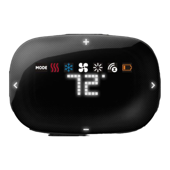
- Page 2 ZTS-500, Z-Wave Smart Thermostat Introduction The ZTS-500 (Figure 1) is a security Z-Wave enabled thermostat designed to control the majority of HVAC systems. A security Enabled Z-Wave Plus Controller must be used in order to fully utilize the product. Users can use local or remote control and monitor the temperature via an App on smart phone or PC while at home or away through a Z-Wave gateway.
-
Page 3: Features List
Support battery low and level report Support Association Groups Association Group-1 is a default status (AUTO) report channel in Z-Wave+ lifeline. Association Group-2 is used for Heat Pump control Association Group-3 is used for Compressor control Advanced features through Z-Wave configuration parameters ... -
Page 4: Physical Installation And Wiring
Physically Installing the Thermostat 1. Open the ZTS-500 by pulling the two sections apart (Figure 2). Use the fingertips of one hand to grip the tab on the front housing. 2. Insert the two included wall anchors into the wall, aligned with two of the mounting holes in the back housing of the thermostat. - Page 5 Figure 2. Open ZTS-500 front housing Figure 3. Open the terminal and mount into the wall...
- Page 6 RC/RH jumper W1 W2 O B G1 G2 Y1 Y2 C RC RH Figure 4. Terminal wiring Figure 5. Install the front housing...
- Page 7 24Vac Power for Cooling 24Vac Power for Heating RC/RH jumper: Most HVAC systems build-in a common heating and cooling transformer. The ZTS-500 has a built-in RH/RC jumper wire to connect RH and RC inputs for this configuration. RC/RH jumper If the HVAC system contains separated heating and cooling transformers, please cut out ...
- Page 8 Non-Heat Pump (standard) HVAC System Important: If there is no C-wire in the HVAC system, the ZTS-500 must be powered by batteries and it will be operated in FLiRS mode after inclusion into a Z-Wave network. Typical wire colour Non-Heat Pump (standard)
- Page 9 Figure 9. Non-heat pump (Standard Gas or Electric) 2-wires HVAC system wiring Heat Pump HVAC System Important: If there is no C-wire in the HVAC system, the ZTS-500 must be powered by batteries and it will be operated in FLiRS mode after inclusion into a Z-Wave network. Typical wire colour...
- Page 10 Typical wire colour Heat Pump HVAC System ZTS-500 Orange O - Cool changeover (heat pump) Blue B - Heat changeover (heat pump) Green G - Fan Yellow Y - Compressor (Heat/Cool) Black (with C-Wire) C - 24Vac Common RC and RH are...
-
Page 11: Product Overview
Setup and Operations Product Overview Mode Heat Cool Fan Brightness Z-Wave Disconnect Battery Low Current Temperature Terminals Figure 13. ZTS-500 Description of Function Keys Symbol Key Description Navigation keys or confirmation keys Scroll keys... - Page 12 User Interface Layout Operation menu: System setup menu:...
- Page 13 - Heat Fan systems: Gas-Powered or Electric-Powered - Fan stage systems: One or two stages fan To prevent abnormal operation, it is important that the ZTS-500 is set to the correct HVAC system type prior to use and Z-Wave inclusion. To set the HVAC system type:...
- Page 14 For Fan Systems: Press > to navigate to the fan system (Fan) screen. Press + or – to entry the setting. Press + or - to select your fan system type, either gas-powered (Gas) or electric-powered (Ele). Press and keep holding > for 2 seconds to confirm your selection.
- Page 15 If the user performs a Reset to Factory Default Settings or Z-Wave Exclusion operation, the ZTS-500 will retain the last selected HVAC system type. Thermostat Mode and Set point For normal setup and operations, ZTS-500 will take the action after key released and it will go back to standby menu after 3 seconds. Step...
- Page 16 Explanations of Set point, Swing, Differential and Dead band HEAT mode: Thermostat controls the temperature according to the following diagram Example: If Heat Set point = 70°F, Swing = 1°F, Differential = 2°F, then => 1 stage heater turns on when room temp is 69°F and off at 71°F. =>...
-
Page 17: Cool Set Point
Example: If Room temperature = 75°F, Dead band = 4°F, Swing = 1°F, Differential = 1°F Heat Set point = 73°F, Cool Set point = 77°F Then it will change the heat set point by +/- buttons. If keep 73°F in heat set point, then the minimum of cool set point will be limited to 77°F, =>... -
Page 18: System Settings
To exit the System Main menu, press and keep holding < key for 3 seconds to exit. To cancel the setting, press < to cancel and back to the previous screen. ZTS-500 will exit the System menu automatically if there is no action (time out) within 30 seconds. - Page 19 Press + or - to adjust LED sleep timer. Range: 3 to 60s or Always On If powered by battery: 5s by default If powered by 24Vac: 60s by default Press > to confirm your selection. Remark: Reducing sleep timer value can enhance ZTS-500 battery service life significantly.
-
Page 20: Battery Low Indication
Press + or – to entry the setting. Press + or - to check the firmware version. Press > or < to back to the previous screen. Z.222 = Z-Wave firmware version 2.22 U.222 = Main MCU firmware version 2.22 Battery Low Indication... -
Page 21: Energy Saving Mode
Cooler will turn on if running in cool mode. Energy Saving Mode User can enable/disable energy saving mode by using Z-Wave BASIC set command only. You may refer to the user manual of Z-Wave primary controller. ZTS-100 will ignore other basic set commands except 0x00 (Off) and 0xFF (Resume). - Page 22 Glossary Devices and nodes are all terms to describe an individual Z-Wave Device or Node device. These are all interchangeable when setting up your Z-Wave network. Inclusion Add a Z-Wave device to the network. Exclusion Remove a Z-Wave device from the network.
- Page 23 Z-Wave operation mode. Select FLiRS or Always Listening Mode ZTS-500 can be powered by 4 x AA batteries, and/or 24Vac C wire. Before inclusion procedure, user need to check the operation mode or the power source of ZTS-500. FLiRS mode (Batt) is targeted for battery operated applications and will enter sleep mode frequently in order to save battery life.
- Page 24 LED indication From the Standby screen, press > or < to navigate to the Z-Wave screen and the Z-Wave LED will continuously flash. Tap + to include the ZTS-500 into the network. There is a “z” animation during Z-Wave searching.
-
Page 25: Notes
3. If the user navigates the menu from Brightness to the right side, the Z-Wave menu will be skipped if the ZTS-500 is already included into the network and it will loop back to the Standby screen by pressing the > key. -
Page 26: Association Group_1
(time out) or unable to exclude the ZTS-500 from the network. Note: All Z-Wave configuration parameter values will keep no changes after excluding the unit from the network, except for the association groups information. The ZTS-500 will retain the last selected HVAC system type. -
Page 27: Table Of Contents
Example: Association groups setting Association group_1 for Auto report to gateway Z-Wave Gateway (Node ID-A) Association group_2 for Heater F-BW8041 (ZFM-80) F-BW8041 (ZFM-80) F-BW8170 (ZTS-500) (Node ID-B) (Node ID-C) Association group_3 for Compressor F-BW8041 (ZFM-80) F-BW8041 (ZFM-80) (Node ID-D) (Node ID-E) - Page 28 Z-Wave Configuration Parameters Different users have different preferred settings of their thermostat, you may use the below configuration parameters to change settings of corresponding functionality. The size of Parameter number is 1 byte; Parameter value can be 1, 2, or 4 bytes.
- Page 29 Example 68 F; input = 680 (0x02A8) in motel service, advance user Unit in C: or administrator can limit the Range from (5 C + dead band) to 37 lower cool set point) Default = 7 Example 20 C; input = 200 (0x00C8) Reset filter counter 7 (0x07) 0 (0x00) (default)
- Page 30 2 (0x02) = Level-2 (middle) , default 3 (0x03) = Level-3 (bright) Sleep timer 12 (0x0C) 3 (0x03) to 60 (0x3C) seconds, 255 (0xFF) = Always On Step size = 1s, Batt = 5s, default 24Vac = 60s, default Repeat basic set counter 13 (0x0D) Value(X) (Association Group A and B...
- Page 31 Press < to cancel and back to the previous screen. Note: If the user performs a Reset to Factory Default Settings, all settings, Z-Wave configuration parameter values and association groups information will reset to default. The ZTS-500 will retain the last selected HVAC system type.
-
Page 32: Frequently Asked Questions
“Thermostat” devices. All Z-Wave products are also labelled with the Z-Wave logos shown below. Q Can I use 2 or more ZTS-500 in my house? If so, what is the max. units? A Yes, you can use multiple ZTS-500s in a single home. The maximum number of units depends on the capabilities of the gateways and controllers. -
Page 33: Checking Accessories
Z-Wave standards. Performance can vary depending on the amount of objects in between Z-Wave devices such as walls and furniture. Every Z-Wave device set up in your network will act as a signal repeater allowing devices to talk to each other and find alternate routes in the case of a reception dead spot. - Page 34 However, there is no guarantee that interference will not occur in a particular installation. If this equipment does cause harmful interference to radio or television reception, which can be determined by turning the equipment off and on, the user is encouraged to try to correct the interference by one or more of the following measures: - Reorient or relocate the receiving antenna.
Need help?
Do you have a question about the ZTS-500 and is the answer not in the manual?
Questions and answers