Table of Contents
Advertisement
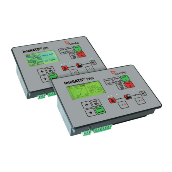
InteliATS
Automatic Transfer Switch Controller
IA-NT STD unit
SW version 2.0, June 2010
June 2010
Copyright © 2010 ComAp s.r.o.
Written by Vlastimil Vostřák
Prague, Czech Republic
®
NT
ComAp, spol. s r.o.
Kundratka 2359/17, 180 00 Praha 8, Czech Republic
Tel: +420 246 012 111, Fax: +420 266 316 647
E-mail: info@comap.cz, www.comap.cz
Reference Guide
Advertisement
Table of Contents

Related Manuals for ComAp InteliATS NT STD


Summary of Contents for ComAp InteliATS NT STD
- Page 1 SW version 2.0, June 2010 Reference Guide June 2010 ComAp, spol. s r.o. Copyright © 2010 ComAp s.r.o. Kundratka 2359/17, 180 00 Praha 8, Czech Republic Written by Vlastimil Vostřák Tel: +420 246 012 111, Fax: +420 266 316 647 Prague, Czech Republic E-mail: info@comap.cz, www.comap.cz...
-
Page 2: Table Of Contents
AMF time chart – genset OK......................47 AMF time chart – genset not started properly................... 47 Voltage phase sequence detection....................48 Gen-set Operation States........................49 List of possible events........................49 InteliATS STD, SW version 2.0, ©ComAp – June 2010 IA-NT- STD-2.0-Reference Guide.pdf... - Page 3 ....57 IL-NT RS232-485 interface (optional card) ..................57 IL-NT S-USB interface (optional card) ....................58 IB-Lite interface (optional card) ......................58 IL-NT BIO8 extension module (optional card)................... 58 InteliATS STD, SW version 2.0, ©ComAp – June 2010 IA-NT- STD-2.0-Reference Guide.pdf...
-
Page 4: Document Information
EC Low Voltage Directive No: 73/23 / EEC and EC Electromagn tic Compatib ility D rec tive 89/336 / EEC based on its design and type, as brought into circulation by us. InteliATS STD, SW version 2.0, ©ComAp – June 2010 IA-NT- STD-2.0-Reference Guide.pdf... -
Page 5: General Guidelines
- remote control via RS232 line - input REM TRANSFER - input REMOTE AUT - input REMOTE TEST or disconnect output Rem START/ST OP and o utputs GCB CLOSE/OPEN and MCB CLOSE/OPEN InteliATS STD, SW version 2.0, ©ComAp – June 2010 IA-NT- STD-2.0-Reference Guide.pdf... - Page 6 In no case touch the terminals for voltage and measurement! Always connect grounding terminals! The following instructions are for qualified personnel only. To avoid personal injury do not perform any action not specified in this Reference guide!!! InteliATS STD, SW version 2.0, ©ComAp – June 2010 IA-NT- STD-2.0-Reference Guide.pdf...
-
Page 7: Description
The gen-set requires a remote start type control unit (e.g. the ComAp InteliLite MRS 10 controller), at le ast a key-start box with an external input for the start/stop signal. - Page 8 If you try to close one contactor before interlock has cleared it can jam and you end up with out supply to load). InteliATS STD, SW version 2.0, ©ComAp – June 2010 IA-NT- STD-2.0-Reference Guide.pdf...
- Page 9 Example application InteliATS STD, SW version 2.0, ©ComAp – June 2010 IA-NT- STD-2.0-Reference Guide.pdf...
-
Page 10: Configurability
*Remote display for IA-NT controllers uses standard IL-NT controller with Remote display software For detailed information about extension modules used with IA-NT controllers, please see the IL-NT, IC-NT, IA-NT, ID-Lite-Accessory Modules manual. InteliATS STD, SW version 2.0, ©ComAp – June 2010 IA-NT- STD-2.0-Reference Guide.pdf... -
Page 11: Il-Nt Rs232 Communication Module
The following procedure is analogic also for other communication modules. 1. Insert a screwdriver into the slot of the cover. 2. Move the screwdriver to set apart the small cover. Be careful! 3. Remove the small cover. InteliATS STD, SW version 2.0, ©ComAp – June 2010 IA-NT- STD-2.0-Reference Guide.pdf... - Page 12 4. Break apart the small cover into two pieces. Do not throw away the smaller part! 5. Take RS 232 communication module. InteliATS STD, SW version 2.0, ©ComAp – June 2010 IA-NT- STD-2.0-Reference Guide.pdf...
- Page 13 When you insert RS 232 communication module, the boot jumper is hidden. For that reason we recommend to use RS 232 communication module with the boot jumper placed on it. See pictures below: RS 232 communication module with the boot jumper. InteliATS STD, SW version 2.0, ©ComAp – June 2010 IA-NT- STD-2.0-Reference Guide.pdf...
-
Page 14: Il-Nt Rs232-485 Communication Module
It is supposed to be used as a service tool. When you need to remove it, grab module in cutouts and pull it up manually. Use the shielded USB A-B cable with this module! Recommended is ComAp cable – Order code: “... -
Page 15: Il-Nt Rd Remote Display Software
Is an ew secured way of monitoring and controlling the gen-set from any point in world using your web browser. It ofers clear overview and control of the state of engine, its settings and history. User friendly. See IB-Lite-Reference Guide and pictures below for further details. InteliATS STD, SW version 2.0, ©ComAp – June 2010 IA-NT- STD-2.0-Reference Guide.pdf... - Page 16 Scada window: Measurement window: InteliATS STD, SW version 2.0, ©ComAp – June 2010 IA-NT- STD-2.0-Reference Guide.pdf...
- Page 17 Setpoints window: History window: This feature requires IB-Lite optional plug-in module and visible connection of controller to Ethernet. InteliATS STD, SW version 2.0, ©ComAp – June 2010 IA-NT- STD-2.0-Reference Guide.pdf...
-
Page 18: Il-Nt Bio8 Hybrid Binary Input/Output Module
Programming is possible only in MAN mode when the engine is not run ning. For more information on programing, see LiteEdit Reference Guide. AUTION Check the statistic values after firmware upgrade. Readjust the values if necessary. InteliATS STD, SW version 2.0, ©ComAp – June 2010 IA-NT- STD-2.0-Reference Guide.pdf... -
Page 19: User Interface
ENTER and PAGE button and th an press again PAGE. On screen will be displeyed the choice of two different User Interfaces. Please see latest IA-NT Operators Guide for detailed description. InteliATS STD, SW version 2.0, ©ComAp – June 2010 IA-NT- STD-2.0-Reference Guide.pdf... -
Page 20: Terminals
Terminal IA-NT STD terminals and face InteliATS STD, SW version 2.0, ©ComAp – June 2010 IA-NT- STD-2.0-Reference Guide.pdf... -
Page 21: Recommended Wiring
The controller is to be mounted onto the switchboard door. Requested cutout size is 175x115mm. Use the screw holders delivered with the controller to fix the controller into the door as described on pictures below. InteliATS STD, SW version 2.0, ©ComAp – June 2010 IA-NT- STD-2.0-Reference Guide.pdf... -
Page 22: Ia-Nt Std - Wiring Diagram
Recommended Wir IA-NT STD – Wiring Diagram REMOTE AUT MAINS FAIL BLOCK REM TRANSFER CONTROL SIGNALS BINARY OUTPUTS GEN-SET CONTROLLER InteliATS STD, SW version 2.0, ©ComAp – June 2010 IA-NT- STD-2.0-Reference Guide.pdf... -
Page 23: Applications
• Break transfer on mains failure • Break return on mains return (Load reclosing) • Test mode (set running and waiting for mains failure) Hardware requirements IA-NT STD InteliATS STD, SW version 2.0, ©ComAp – June 2010 IA-NT- STD-2.0-Reference Guide.pdf... -
Page 24: Amf Using Two-Position Ats
Break trans fer on mains failure • Break return on mains return (Load reclosing) • Test mode (set running and waiting for mains failure) Hardware requirements IA-NT STD InteliATS STD, SW version 2.0, ©ComAp – June 2010 IA-NT- STD-2.0-Reference Guide.pdf... -
Page 25: Amf Using Three-Position Ats
Break trans fer on mains failure • Break return on mains return (Load reclosing) • Test mode (set running and waiting for mains failure) Hardware requirements IA-NT STD InteliATS STD, SW version 2.0, ©ComAp – June 2010 IA-NT- STD-2.0-Reference Guide.pdf... -
Page 26: Amf + Manual Transfer & Neutral Control Using Three-Position Ats
Request for switching to neutral position – the highest priority, overrides MCB & GCB state, forces switch to neutral position. After deactivating return to previous state (MCB or GCB) Hardware requirements IA-NT STD InteliATS STD, SW version 2.0, ©ComAp – June 2010 IA-NT- STD-2.0-Reference Guide.pdf... -
Page 27: Amf + No Battery Operation
GCB is opened, 24V AC/DC power supply source is unlocked and switched to Mains • MCB is closed • Gen-set is stopped Hardware requirements IA-NT STD 24V/2.5A AC/DC power supply InteliATS STD, SW version 2.0, ©ComAp – June 2010 IA-NT- STD-2.0-Reference Guide.pdf... -
Page 28: Controllers In Cascade
Automatic remote gen-set start when the mains fails (AUT mode) • Cascade controlled by Master • Consequent changeover on slave controllers • Simple wiring Hardw re requirements IA-NT PWR (1 to n) x IA-NT PWR or STD InteliATS STD, SW version 2.0, ©ComAp – June 2010 IA-NT- STD-2.0-Reference Guide.pdf... - Page 29 Cascade, wiring B, Mains Fail timing diagram with configuration description Cascade, wiring B, Mains Return timing diagram with configuration description InteliATS STD, SW version 2.0, ©ComAp – June 2010 IA-NT- STD-2.0-Reference Guide.pdf...
-
Page 30: Getting Started
The capacitor size should be 5 000 microFarad to withstand 150ms voltage dip under following conditions: Voltage before dip is 12V, after 150ms the voltage recovers to min. allowed voltage, i.e. 8V Before the battery is discharged the message "Low BackupBatt" appears. InteliATS STD, SW version 2.0, ©ComAp – June 2010 IA-NT- STD-2.0-Reference Guide.pdf... - Page 31 Use as short as possible cable to the grounding point on the switchboard • Use cable min. 2,5mm • The “-“ terminal of the battery has to be properly grounded InteliATS STD, SW version 2.0, ©ComAp – June 2010 IA-NT- STD-2.0-Reference Guide.pdf...
- Page 32 IL-NT BIO8 extension module connection InteliATS STD, SW version 2.0, ©ComAp – June 2010 IA-NT- STD-2.0-Reference Guide.pdf...
-
Page 33: Three Phase Applications
Generator (and mains) single-phase voltage has to be connected to all three-voltage terminals L1, L2 and L3. Voltage measurement GENERATOR MAINS Switchboard lighting strikes protection according standard regulation is expected!!! InteliATS STD, SW version 2.0, ©ComAp – June 2010 IA-NT- STD-2.0-Reference Guide.pdf... - Page 34 Binary inputs 4k7 Ω Power Supply Battery Binary outputs LOAD Power Supply Battery InteliATS STD, SW version 2.0, ©ComAp – June 2010 IA-NT- STD-2.0-Reference Guide.pdf...
-
Page 35: Inputs And Outputs
Binary inputs IA-NT - default BI1 GCB Feedback BI2 MCB Feedback BI3 GenReadyToLoad BI4 MainsFailBlock* *InteliATS STD HW version 1.3 provides 3 binary inputs, higher versions provide 4 binary inputs InteliATS STD, SW version 2.0, ©ComAp – June 2010 IA-NT- STD-2.0-Reference Guide.pdf... -
Page 36: Binary Inputs - List
Mains and Gen-set voltage measuring inputs connected to the repspective power sources.Then this binary input tells the controller if Mains is healthy to be able to respond to Mains failure. InteliATS STD, SW version 2.0, ©ComAp – June 2010 IA-NT- STD-2.0-Reference Guide.pdf... -
Page 37: Binary Outputs Ia-Nt - Default
AL Mains Fail Output closes if the mains over/under voltage alarm, voltage asymmetry alarm or mains over/under frequency alarm activates. The output opens, if • alarm is not active InteliATS STD, SW version 2.0, ©ComAp – June 2010 IA-NT- STD-2.0-Reference Guide.pdf... - Page 38 AUT mode. Neutral Pos Switches AT S switch to its neutral position. Falut Reset The output is a copy of Fault Reset button on controller and binary input FaultResButton. InteliATS STD, SW version 2.0, ©ComAp – June 2010 IA-NT- STD-2.0-Reference Guide.pdf...
-
Page 39: Setpoints
See the table below for a description of the engine start evaluation. If MaxStartDel is longer then 600 s it means there is NO TIMEOUT. Step: Range: 0 – 600 s, 601 s = NO TIMEOUT InteliATS STD, SW version 2.0, ©ComAp – June 2010 IA-NT- STD-2.0-Reference Guide.pdf... - Page 40 The set point influences the behavior of the output Gen Start/Stop. CLOSE-ON: Gen-set should start when the output Gen Start/Stop is closed. CLOSE-OFF: Gen-set should start when the output Gen Start/Stop is opened. InteliATS STD, SW version 2.0, ©ComAp – June 2010 IA-NT- STD-2.0-Reference Guide.pdf...
-
Page 41: Amf Settings
Delay after MCB opening to GCB closing if the setpoint MCB Opens On set to GENRUN Step: 0.1s Range: 0 – 600.0 s The time charts bellow show recommended setting of AMF Settings: Transfer Del setpoint. InteliATS STD, SW version 2.0, ©ComAp – June 2010 IA-NT- STD-2.0-Reference Guide.pdf... - Page 42 After that, the MCB is opened, Transfer Del timer is started and the GCB is closed after the timer elapses. This option should be used for MCBs using 230V control and not equipped with the undervoltage coil. InteliATS STD, SW version 2.0, ©ComAp – June 2010 IA-NT- STD-2.0-Reference Guide.pdf...
-
Page 43: Function Description
• If the problem on the gen-set side appears, all faults messages are auto-quit and no next operation is be blocked • Gen-set Start/Stop signal stays active InteliATS STD, SW version 2.0, ©ComAp – June 2010 IA-NT- STD-2.0-Reference Guide.pdf... - Page 44 ARNING If an red alarm is present and the gen-set is in AUT mode, it can start by self after all red alarms becomes inactive and are acknowledged!!! InteliATS STD, SW version 2.0, ©ComAp – June 2010 IA-NT- STD-2.0-Reference Guide.pdf...
-
Page 45: Circuit Breakers Timing
Conditions: AUTO Mode, Mains =off, MCB = opened, GCB = closed, gen-set loaded. Mains returns: GCB opens (according 3., MainsReturnDel), MCB closes (1 sec) GCB opened MCB closed 1 sec. InteliATS STD, SW version 2.0, ©ComAp – June 2010 IA-NT- STD-2.0-Reference Guide.pdf... -
Page 46: Alarm Management
When the mains failure comes u p, mains circuit breaker is opened. Possible mains failure reasons: List of possible events Mains failure is not written to alarm list! InteliATS STD, SW version 2.0, ©ComAp – June 2010 IA-NT- STD-2.0-Reference Guide.pdf... -
Page 47: Amf Time Chart - Genset Ok
AMF time chart – genset OK AMF time chart – genset not started properly Hint: * Please see the AMF Setting: MaxStartDel setpoint description for more details. InteliATS STD, SW version 2.0, ©ComAp – June 2010 IA-NT- STD-2.0-Reference Guide.pdf... -
Page 48: Voltage Phase Sequence Detection
(e.g. L1, L3, L2 or L 2, L1, L3) following alarms are detected: Gen CCW Rot = wrong generator phase sequence Mains CCW Rot = wrong mains phase sequence InteliATS STD, SW version 2.0, ©ComAp – June 2010 IA-NT- STD-2.0-Reference Guide.pdf... -
Page 49: Gen-Set Operation States
If the input Emergency Stop is opened shutdown is immediately activated. Wrn Stop Fail Gen-set stop failed. The alarm appears if the STOP command fails and the START command was issued before. InteliATS STD, SW version 2.0, ©ComAp – June 2010 IA-NT- STD-2.0-Reference Guide.pdf... -
Page 50: Remote Control And Data Logging
GND‘s Battery PC software – LiteEdit On the PC (fo r direct or modem connectio n) has to be installed the ComAp’s software package LiteEd it. (based on Windows 95 or newer platfo LiteEdit enabl • read the quantities •... -
Page 51: Remote Communication
Analog modem modem modem modem Mobile SIM card setting • Adjust SIM card in GSM modem following way: • enable data connection (when required) • no PIN code InteliATS STD, SW version 2.0, ©ComAp – June 2010 IA-NT- STD-2.0-Reference Guide.pdf... -
Page 52: Il-Nt-Rd Remote Display Software
Choosing the wrong type of firmware may result in non-functional controller. • Press "OK" button to programm the firmware to the controller. InteliATS STD, SW version 2.0, ©ComAp – June 2010 IA-NT- STD-2.0-Reference Guide.pdf... -
Page 53: Il-Nt-Rd Wiring
Direct RS232 connection HW module: IL-NT-RS232 Master controller settings: ControllerAddr = 1..32 COM1 Mode = DIRECT Up to 2 meters: Reco mmended to use our standard AT-LINK cable. InteliATS STD, SW version 2.0, ©ComAp – June 2010 IA-NT- STD-2.0-Reference Guide.pdf... - Page 54 COM1 Mode = DIRECT COM2 Mode = DIRECT It is possible to make a RS232 direct connection with IL-NT-RS232 module on one side and IL-NT- RS232-485 module on the other side. InteliATS STD, SW version 2.0, ©ComAp – June 2010 IA-NT- STD-2.0-Reference Guide.pdf...
-
Page 55: Function Description
• All ID-Lite standard software from ver. 1.0 • Chosen InteliATS , InteliLite and ID-Lite customer branches Some of the future InteliATS , InteliLite , ID-Lite versions may require upgrade of the IL-NT-RD software. InteliATS STD, SW version 2.0, ©ComAp – June 2010 IA-NT- STD-2.0-Reference Guide.pdf... -
Page 56: Technical Data
:99, EN 50082-2:97 Vibration - 25 Hz, ±1,6mm 25 - 100 Hz, a = 4 g Shocks a = 200 m/s Dimensions and weight Dimensions 180x120x55mm Weight 450g InteliATS STD, SW version 2.0, ©ComAp – June 2010 IA-NT- STD-2.0-Reference Guide.pdf... -
Page 57: Mains And Generator
IL-NT RS232-485 interface (optional card) Plugs into IA-NT controller COMMUNICATION MODULE port. Maximal distance 10m (RS232), 1200m (RS485) Maximum Speed Up to 57.6 kBd (DIRECT), 38.4kBd Analog modem, 9.6 kBd digital modem InteliATS STD, SW version 2.0, ©ComAp – June 2010 IA-NT- STD-2.0-Reference Guide.pdf... -
Page 58: Il-Nt S-Usb Interface (Optional Card)
Binary open collector outputs Number of outputs Maximum current per pin 0.5 A Maximum switching common current Maximum switching voltage 36 VDC Binary inputs are not galvanically isolated. InteliATS STD, SW version 2.0, ©ComAp – June 2010 IA-NT- STD-2.0-Reference Guide.pdf...
Need help?
Do you have a question about the InteliATS NT STD and is the answer not in the manual?
Questions and answers