Table of Contents
Advertisement
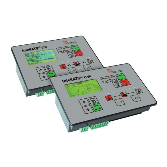
InteliATS
Automatic Transfer Switch Controller
IA-NT PWR unit
SW version 1.2, January 2010
January 2010
Copyright © 2010 ComAp s.r.o.
Written by Vlastimil Vostřák
Prague, Czech Republic
®
NT
ComAp, spol. s r.o.
Kundratka
2359/17, 180 00 Praha 8, Czech Republic
Tel: +420
246 012
111, Fax: +420 246 316 647
E-mail: info@comap.cz, www.comap.cz
Reference Guide
Advertisement
Table of Contents

Subscribe to Our Youtube Channel
Related Manuals for ComAp InteliATS NT PWR


Summary of Contents for ComAp InteliATS NT PWR
- Page 1 Automatic Transfer Switch Controller IA-NT PWR unit SW version 1.2, January 2010 Reference Guide January 2010 ComAp, spol. s r.o. Copyright © 2010 ComAp s.r.o. Kundratka 2359/17, 180 00 Praha 8, Czech Republic Written by Vlastimil Vostřák Tel: +420 246 012...
-
Page 2: Table Of Contents
Function Description..........................47 Operating modes..........................47 Circuit breakers timing ........................50 Alarm Management ..........................52 Warning (WRN) ..........................52 Trip (TRP)............................52 Mains failure (MF) ..........................52 InteliATS PWR, SW version 1.0, ©ComAp – March 2009 IA-NT- PWR-1.0-Reference Guide R1.pdf... - Page 3 IL-NT RS232 interface (optional card) ....................68 IL-NT RS232-485 interface (optional card) ..................69 IL-NT S-USB interface (optional card) ....................69 IB-Lite interface (optional card) ......................69 InteliATS PWR, SW version 1.0, ©ComAp – March 2009 IA-NT- PWR-1.0-Reference Guide R1.pdf...
-
Page 4: Document Information
EC Low Voltage Directive No: 73/23 / EEC and EC Electromagnetic Compatibility Directive 89/336 / EEC based on its design and type, as brought into circulation by us. InteliATS PWR, SW version 1.0, ©ComAp – March 2009 IA-NT- PWR-1.0-Reference Guide R1.pdf... -
Page 5: General Guidelines
In this case use Boot load (jumper) programming – close Boot jumper and follow instructions in LiteEdit, download correct software. ComAp believes that all information provided herein is correct and reliable and reserves the right to update at any time. ComAp does not assume any responsibility for its use unless otherwise expressly undertaken. - Page 6 In any case do not disconnect InteliATS current transformer terminals! The following instructions are for qualified personnel only. To avoid personal injury do not perform any action not specified in this Reference guide!!! InteliATS PWR, SW version 1.0, ©ComAp – March 2009 IA-NT- PWR-1.0-Reference Guide R1.pdf...
-
Page 7: Description
In the case of any mains supply disproportion it will send a remote start command to the gen-set and make change over for both generator and mains contactors. The gen-set requires a remote start type control unit (e.g. the ComAp InteliLite MRS 10 controller), at least a key-start box with an external input for the start/stop signal. -
Page 8: Configurability
*Remote display for IA-NT controllers uses standard IL-NT controller with Remote display software For detailed information about extension modules used with IA-NT controllers, please see the IL-NT, IC-NT-Accessory Modules manual. InteliATS PWR, SW version 1.0, ©ComAp – March 2009 IA-NT- PWR-1.0-Reference Guide R1.pdf... -
Page 9: Il-Nt Rs232 Communication Module
1. Insert a screwdriver into the slot of the cover. 2. Move the screwdriver to set apart the small cover. Be careful! 3. Remove the small cover. InteliATS PWR, SW version 1.0, ©ComAp – March 2009 IA-NT- PWR-1.0-Reference Guide R1.pdf... - Page 10 4. Break apart the small cover into two pieces. Do not throw away the smaller part! 5. Take RS 232 communication module. InteliATS PWR, SW version 1.0, ©ComAp – March 2009 IA-NT- PWR-1.0-Reference Guide R1.pdf...
- Page 11 When you insert RS 232 communication module, the boot jumper is hidden. For that reason we recommend to use RS 232 communication module with the boot jumper placed on it. See pictures below: RS 232 communication module with the boot jumper. InteliATS PWR, SW version 1.0, ©ComAp – March 2009 IA-NT- PWR-1.0-Reference Guide R1.pdf...
-
Page 12: Il-Nt Rs232-485 Communication Module
It is supposed to be used as a service tool. When you need to remove it, grab module in cutouts and pull it up manually. Use the shielded USB A-B cable with this module! Recommended is ComAp cable – Order code: “... -
Page 13: Il-Nt Rd Remote Display Software
Programming is possible only in OFF mode when the engine is not running. For more information on programing, see LiteEdit Reference Guide. AUTION Check the statistic values after firmware upgrade. Readjust the values if necessary. InteliATS PWR, SW version 1.0, ©ComAp – March 2009 IA-NT- PWR-1.0-Reference Guide R1.pdf... -
Page 14: User Interface
ENTER and PAGE button and than press again PAGE. On screen will be displeyed the choice of two different User Interfaces. Please see latest IA-NT Operator Guide for detailed description. InteliATS PWR, SW version 1.0, ©ComAp – March 2009 IA-NT- PWR-1.0-Reference Guide R1.pdf... -
Page 15: Terminals
Terminals IA-NT PWR terminals and face InteliATS PWR, SW version 1.0, ©ComAp – March 2009 IA-NT- PWR-1.0-Reference Guide R1.pdf... -
Page 16: Recommended Wiring
MCB FEEDBACK GCB FEEDBACK REMOTE AUT MAINS FAIL BLOCK GEN READY TO LOAD CONTROL SIGNALS BINARY OUTPUTS GEN-SET CONTROLLER MCB and GCB is recommended to be mechanically interlocked. InteliATS PWR, SW version 1.0, ©ComAp – March 2009 IA-NT- PWR-1.0-Reference Guide R1.pdf... -
Page 17: Applications
• Break return on mains return (Load reclosing) • Test mode (set running and waiting for mains failure) Hardware requirements IA-NT PWR Setpoints MCB Logic = “CLOSE-OFF” InteliATS PWR, SW version 1.0, ©ComAp – March 2009 IA-NT- PWR-1.0-Reference Guide R1.pdf... -
Page 18: Amf Using Two Separate Breakers With Feedbacks (Mcb And Gcb) + Test On Load
RetFromIsland = “AUTO” – automatic return (MCB Close) to mains after TEST RetFromIsland = “MANUAL” – mual return to mains (MCB Close) after TEST – IA-NT goes to MAN mode. InteliATS PWR, SW version 1.0, ©ComAp – March 2009 IA-NT- PWR-1.0-Reference Guide R1.pdf... -
Page 19: Amf Using Two-Position Ats With Feedback
• Break return on mains return (Load reclosing) • Test mode (set running and waiting for mains failure) Hardware requirements IA-NT PWR Setpoints MCB Logic = “CLOSE-ON” InteliATS PWR, SW version 1.0, ©ComAp – March 2009 IA-NT- PWR-1.0-Reference Guide R1.pdf... -
Page 20: Amf Using Three-Position Ats With Feedbacks
• Break return on mains return (Load reclosing) • Test mode (set running and waiting for mains failure) Hardware requirements IA-NT PWR Setpoints MCB Logic = “CLOSE-ON” InteliATS PWR, SW version 1.0, ©ComAp – March 2009 IA-NT- PWR-1.0-Reference Guide R1.pdf... -
Page 21: Amf + Manual Transfer & Neutral Control Using Three-Position Ats
Request for switching to neutral position – the highest priority, overrides MCB & GCB state, forces switch to neutral position. After deactivating return to previous state (MCB or GCB) Hardware requirements IA-NT PWR Setpoints MCB Logic = “CLOSE-ON” InteliATS PWR, SW version 1.0, ©ComAp – March 2009 IA-NT- PWR-1.0-Reference Guide R1.pdf... -
Page 22: Amf + No Battery Operation
GCB is opened, 24V AC/DC power supply source is unlocked and switched to Mains • MCB is closed • Gen-set is stopped Hardware requirements IA-NT PWR 24V/2.5A AC/DC power supply InteliATS PWR, SW version 1.0, ©ComAp – March 2009 IA-NT- PWR-1.0-Reference Guide R1.pdf... -
Page 23: Getting Started
Voltage before dip is 12V, after 150ms the voltage recovers to min. allowed voltage, i.e. 8V Before the battery is discharged the message "Low BackupBatt" appears. InteliATS PWR, SW version 1.0, ©ComAp – March 2009 IA-NT- PWR-1.0-Reference Guide R1.pdf... - Page 24 Binary output protections Do not connect binary outputs directly to DC relays without protection diodes, even if they are not connected directly to controller outputs. InteliATS PWR, SW version 1.0, ©ComAp – March 2009 IA-NT- PWR-1.0-Reference Guide R1.pdf...
-
Page 25: Three Phase Applications
Voltage measurement GENERATOR MAINS GENERATOR MAINS No separation transformers for three wires voltage connection (without N) are needed. Switchboard lighting strikes protection according standard regulation is expected!!! InteliATS PWR, SW version 1.0, ©ComAp – March 2009 IA-NT- PWR-1.0-Reference Guide R1.pdf... -
Page 26: Single Phase Applications
To run a single-phase application, the following set points have to be set: Amps Unbal Sd to 200 % Gener Protect: Amps Unbal Del to 60,0 s Gener Protect: InteliATS PWR, SW version 1.0, ©ComAp – March 2009 IA-NT- PWR-1.0-Reference Guide R1.pdf... - Page 27 Binary inputs 4k7 Ω Power Supply Battery Binary outputs LOAD Power Supply Battery InteliATS PWR, SW version 1.0, ©ComAp – March 2009 IA-NT- PWR-1.0-Reference Guide R1.pdf...
-
Page 28: Inputs And Outputs
Engine running only Valid if checkbox “Engine running only” is checked Control Use this setting to configure the desired function from the list below. InteliATS PWR, SW version 1.0, ©ComAp – March 2009 IA-NT- PWR-1.0-Reference Guide R1.pdf... -
Page 29: Binary Inputs Ia-Nt - Default
Also the button Fault reset, is not blocked at all and buttons Start and Stop in MAN mode are not blocked. InteliATS PWR, SW version 1.0, ©ComAp – March 2009 IA-NT- PWR-1.0-Reference Guide R1.pdf... - Page 30 In MAN mode this input switches a three position ATS switch to its neutral position – it activates the binary output NeutralPosition and switches the MCB and GCB off. InteliATS PWR, SW version 1.0, ©ComAp – March 2009 IA-NT- PWR-1.0-Reference Guide R1.pdf...
-
Page 31: Binary Outputs Ia-Nt - Default
Supposed time to close (reaction time) of GCB is 0.1 sec. GCB ON Coil The output activates Generator Circuit Breaker coil. GCB OFF Coil The output deactivates Generator Circuit Breaker coil. InteliATS PWR, SW version 1.0, ©ComAp – March 2009 IA-NT- PWR-1.0-Reference Guide R1.pdf... - Page 32 • FAULT RESET is pressed AL Gen Volts The output closes if the generator over/under voltage alarm or voltage asymmetry alarm activates. The output opens, if InteliATS PWR, SW version 1.0, ©ComAp – March 2009 IA-NT- PWR-1.0-Reference Guide R1.pdf...
- Page 33 • alarm is not active and • FAULT RESET is pressed AL Overcurrent Output closes if the generator • IDMT over current or • current unbalance or InteliATS PWR, SW version 1.0, ©ComAp – March 2009 IA-NT- PWR-1.0-Reference Guide R1.pdf...
- Page 34 Output activates when the controller is not in AUT mode. Neutral Pos Switches ATS switch to its neutral position. Neutral Coil Activates the neutral position coil of the ATS switch. InteliATS PWR, SW version 1.0, ©ComAp – March 2009 IA-NT- PWR-1.0-Reference Guide R1.pdf...
-
Page 35: Setpoints
WARNING! When you change the firmware, statistics can be invalid! PT Ratio [/1] Gen-set potential transformers ratio. Step: 0,1 V / V Range: 0,1 – 500,0 V / V InteliATS PWR, SW version 1.0, ©ComAp – March 2009 IA-NT- PWR-1.0-Reference Guide R1.pdf... - Page 36 Modbus protocol. See detailed description in InteliCommunication guide. For details on communic. speed and other technical parameters please see chapter Technical Data. For detail description see chapter Modbus protocol. Register oriented modbus is supported. InteliATS PWR, SW version 1.0, ©ComAp – March 2009 IA-NT- PWR-1.0-Reference Guide R1.pdf...
-
Page 37: Engine Params
See the table below for a description of the engine start evaluation. If MaxStartDel is longer then 600 s it means there is NO TIMEOUT. Step: Range: 0 – 600 s, 601 s = NO TIMEOUT InteliATS PWR, SW version 1.0, ©ComAp – March 2009 IA-NT- PWR-1.0-Reference Guide R1.pdf... - Page 38 (Start/Stop output is deactivated). Step: Range: 0 – 3601 sec Value 3601 means the controller doesn’t care for the engine is stopped (Wrn Stop Fail is never announced). InteliATS PWR, SW version 1.0, ©ComAp – March 2009 IA-NT- PWR-1.0-Reference Guide R1.pdf...
-
Page 39: Generprotect
IDMT Curr No action 20 s 0,2 s No action 200 s 20 s Reaction time No action No action 200 s 20 s (time > 900 s) InteliATS PWR, SW version 1.0, ©ComAp – March 2009 IA-NT- PWR-1.0-Reference Guide R1.pdf... - Page 40 0.1s Range: 0.0 – 600.0 s Volt Unbal Trp Threshold for generator voltage unbalance alarm. Step: 1% of Nominal voltage Range: 0 – 200% of Nominal voltage InteliATS PWR, SW version 1.0, ©ComAp – March 2009 IA-NT- PWR-1.0-Reference Guide R1.pdf...
-
Page 41: Amf Settings
Delay after GCB opening to MCB closing during the return procedure. Delay after MCB opening to GCB closing if the setpoint MCB Opens On set to GENRUN Step: 0.1s Range: 0 – 600.0 s InteliATS PWR, SW version 1.0, ©ComAp – March 2009 IA-NT- PWR-1.0-Reference Guide R1.pdf... - Page 42 Mains >Freq Threshold for mains overfrequency. All three phases are checked. Maximum out of three is used. Step: 0.1% of Nominal frequency Range: 50 (Mains <Freq) – 150.0% InteliATS PWR, SW version 1.0, ©ComAp – March 2009 IA-NT- PWR-1.0-Reference Guide R1.pdf...
- Page 43 In the case MCB Logic = “CLOSE-OFF” it is necessary to change externally the polarity of the output signal. ReturnFromTEST [MANUAL / AUTO] The set point influences the behavior of the TEST mode. MANUAL: 1) Select TEST, gen-sets starts and running unloaded InteliATS PWR, SW version 1.0, ©ComAp – March 2009 IA-NT- PWR-1.0-Reference Guide R1.pdf...
-
Page 44: Date/Time
DISABLED: Automatic switching between summer and wintertime is disabled. WINTER (SUMMER) : Automatic switching between summer and wintertime is enabled and it is set to winter (summer) season. WINTER-S (SUMMER-S) : Modification for southern hemisphere. InteliATS PWR, SW version 1.0, ©ComAp – March 2009 IA-NT- PWR-1.0-Reference Guide R1.pdf... -
Page 45: Sms/E-Mail
During the time the IA-NT is trying to send an active call type, incoming calls are blocked. Yel Alarm Msg [DISABLED, ENABLED] Set this setpoint to YES if you want to get messages when a yellow (warning) alarm occurs. InteliATS PWR, SW version 1.0, ©ComAp – March 2009 IA-NT- PWR-1.0-Reference Guide R1.pdf... - Page 46 For GSM numbers use either national format (i.e. like number you will dial if you want to make a local call) or full international format with "+" character followed by international prefix in the begining. This setpoint can be modified from PC only! InteliATS PWR, SW version 1.0, ©ComAp – March 2009 IA-NT- PWR-1.0-Reference Guide R1.pdf...
-
Page 47: Function Description
The engine can run without load unlimited time. The controller does not automatically stop the running gen-set in MAN Mode and does not start the gen-set when power cut comes. InteliATS PWR, SW version 1.0, ©ComAp – March 2009 IA-NT- PWR-1.0-Reference Guide R1.pdf... - Page 48 Mains operation Transfer Del MCB CLOSE/OPEN on and then engine stop sequence performed Mains failed means mains over/under -voltage, over/under -frequency, voltage assymetry (preset delay must elapse) InteliATS PWR, SW version 1.0, ©ComAp – March 2009 IA-NT- PWR-1.0-Reference Guide R1.pdf...
- Page 49 If a shutdown or other red alarm comes while the load is supplied from the gen-set and the mains is healthy, the load is switched back to the mains. AUTION The gen-set starts automatically and is always running in TEST mode! InteliATS PWR, SW version 1.0, ©ComAp – March 2009 IA-NT- PWR-1.0-Reference Guide R1.pdf...
-
Page 50: Circuit Breakers Timing
Relation between Mains return and MCB OFF Mode, GCB and MCB are opened Mains return MCB closed (only when genset is not running and GCB is opened) MCB Close Del InteliATS PWR, SW version 1.0, ©ComAp – March 2009 IA-NT- PWR-1.0-Reference Guide R1.pdf... - Page 51 Situation 2: ReturnFromTEST=MANUAL, Mains =OK, MCB is closed, gen-set is running. Press MCB on/off -> MCB opens, GCB closes (Transfer Del), gen-set is running loaded. MCB opened GCB closed Transfer Del InteliATS PWR, SW version 1.0, ©ComAp – March 2009 IA-NT- PWR-1.0-Reference Guide R1.pdf...
-
Page 52: Alarm Management
When the mains failure comes up, mains circuit breaker is opened. Possible mains failure reasons: List of possible events Mains failure is not written to alarm list! InteliATS PWR, SW version 1.0, ©ComAp – March 2009 IA-NT- PWR-1.0-Reference Guide R1.pdf... -
Page 53: Amf Time Chart - Genset Ok
For more details please see the: AMF Setting: MinStabTime & MaxStartDel setpoint description, ** AMF Setting: MCB Opens On & Transfer Del setpoint description, *** AMF Setting: MCB Close Del setpoint description InteliATS PWR, SW version 1.0, ©ComAp – March 2009 IA-NT- PWR-1.0-Reference Guide R1.pdf... -
Page 54: Voltage Phase Sequence Detection
T ime delay closed 5 or 2 sec BI G CB feedback active Alarm: G CB fail You can solve state of MCB fail by pressing Fault Reset button. InteliATS PWR, SW version 1.0, ©ComAp – March 2009 IA-NT- PWR-1.0-Reference Guide R1.pdf... -
Page 55: Gen-Set Operation States
Wrn Stop Fail Gen-set stop failed. The alarm appears if the STOP command fails and the START command was issued before. Low BackupBatt RTC backup battery is flat InteliATS PWR, SW version 1.0, ©ComAp – March 2009 IA-NT- PWR-1.0-Reference Guide R1.pdf... -
Page 56: History File
Generator current L2 Generator current L3 Mains voltage L1 Mains voltage L2 Mains voltage L3 Mfrq Mains frequency UBat Battery voltage Binary inputs IA-NT BOUT Binary outputs IA-NT InteliATS PWR, SW version 1.0, ©ComAp – March 2009 IA-NT- PWR-1.0-Reference Guide R1.pdf... -
Page 57: Remote Control And Data Logging
Required the same voltage potential between GND‘s Battery PC software – LiteEdit On the PC (for direct or modem connection) has to be installed the ComAp’s software package LiteEdit. (based on Windows 95 or newer platform) LiteEdit enables: • read the quantities •... - Page 58 Gen <Freq Trp 85,0 % 8298 110,0 Unsigned 16 Gener Protect Gen Freq Del 3,0 s 8297 600,0 Unsigned 16 AMF Settings RetFromIsland AUTO 9590 String list InteliATS PWR, SW version 1.0, ©ComAp – March 2009 IA-NT- PWR-1.0-Reference Guide R1.pdf...
- Page 59 8535 Integer 8 Generator Gen Ld Char L3 8628 Char Generator Gen Freq 50,0 Hz 8210 Unsigned 16 Generator Gen V L1-N 230 V 8192 Unsigned 16 InteliATS PWR, SW version 1.0, ©ComAp – March 2009 IA-NT- PWR-1.0-Reference Guide R1.pdf...
- Page 60 8480 Unsigned 8 IA Info FW Branch 8707 Unsigned 8 IA Info PasswordDecode ##### 9090 Unsigned 32 Date/Time Time ##### 24554 Time Date/Time Date ##### 24553 Date InteliATS PWR, SW version 1.0, ©ComAp – March 2009 IA-NT- PWR-1.0-Reference Guide R1.pdf...
-
Page 61: Remote Communication
Mobile SIM card setting • Adjust SIM card in GSM modem following way: • enable data connection (when required) • no PIN code InteliATS PWR, SW version 1.0, ©ComAp – March 2009 IA-NT- PWR-1.0-Reference Guide R1.pdf... -
Page 62: Il-Nt-Rd Remote Display Software
Choosing the wrong type of firmware may result in non-functional controller. • Press "OK" button to programm the firmware to the controller. InteliATS PWR, SW version 1.0, ©ComAp – March 2009 IA-NT- PWR-1.0-Reference Guide R1.pdf... -
Page 63: Il-Nt-Rd Wiring
Direct RS232 connection HW module: IL-NT-RS232 Master controller settings: ControllerAddr = 1..32 COM1 Mode = DIRECT Up to 2 meters: Recommended to use our standard AT-LINK cable. InteliATS PWR, SW version 1.0, ©ComAp – March 2009 IA-NT- PWR-1.0-Reference Guide R1.pdf... - Page 64 COM2 Mode = DIRECT It is possible to make a RS232 direct connection with IL-NT-RS232 module on one side and IL-NT- RS232-485 module on the other side. InteliATS PWR, SW version 1.0, ©ComAp – March 2009 IA-NT- PWR-1.0-Reference Guide R1.pdf...
-
Page 65: Function Description
• All ID-Lite standard software from ver. 1.0 • Chosen InteliATS , InteliLite and ID-Lite customer branches Some of the future InteliATS , InteliLite , ID-Lite versions may require upgrade of the IL-NT-RD software. InteliATS PWR, SW version 1.0, ©ComAp – March 2009 IA-NT- PWR-1.0-Reference Guide R1.pdf... -
Page 66: Maintenance
6. Plug the modules back into the slots. 7. Power the controller on, adjust date and time and check all setpoints. InteliATS PWR, SW version 1.0, ©ComAp – March 2009 IA-NT- PWR-1.0-Reference Guide R1.pdf... -
Page 67: Technical Data
EN 50082-1:99, EN 50082-2:97 Vibration 5 - 25 Hz, ±1,6mm 25 - 100 Hz, a = 4 g Shocks a = 200 m/s Dimensions and weight Dimensions 180x120x55mm Weight 450g InteliATS PWR, SW version 1.0, ©ComAp – March 2009 IA-NT- PWR-1.0-Reference Guide R1.pdf... -
Page 68: Mains And Generator
ADVANTECH – PCL-745B or PCL745S: Dual port RS422/485 Interface card, automatic RS485 bus supervision, no external data flow control signals, galvanic isolated For details on all IA-NT extension and communication modules see IL-NT, IC-NT-Accessory Modules manual. InteliATS PWR, SW version 1.0, ©ComAp – March 2009 IA-NT- PWR-1.0-Reference Guide R1.pdf... -
Page 69: Il-Nt Rs232-485 Interface (Optional Card)
9.6 kBd digital modem, 57.6 kBd (MODBUS) Use only shielded A-B USB cables up to 5m length. Recommend USB cable: USB-LINK CABLE 1.8M – ComAp A-B USB cable. IB-Lite interface (optional card) Plugs into IA-NT controller COMMUNICATION MODULE port.
Need help?
Do you have a question about the InteliATS NT PWR and is the answer not in the manual?
Questions and answers