Cisco ASR-920-24SZ-IM Hardware Installation Manual
Aggregation services router
Hide thumbs
Also See for ASR-920-24SZ-IM:
- Installation manual (134 pages) ,
- Configuration manual (13 pages)
Table of Contents
Advertisement
Quick Links
Cisco ASR-920-24SZ-IM, ASR-920-24SZ-M, ASR-920-24TZ-M
Aggregation Services Router Hardware Installation Guide
First Published: 2016-07-04
Americas Headquarters
Cisco Systems, Inc.
170 West Tasman Drive
San Jose, CA 95134-1706
USA
http://www.cisco.com
Tel: 408 526-4000
800 553-NETS (6387)
Fax: 408 527-0883
Text Part Number:
Advertisement
Table of Contents

Related Manuals for Cisco ASR-920-24SZ-IM


Summary of Contents for Cisco ASR-920-24SZ-IM
- Page 1 Cisco ASR-920-24SZ-IM, ASR-920-24SZ-M, ASR-920-24TZ-M Aggregation Services Router Hardware Installation Guide First Published: 2016-07-04 Americas Headquarters Cisco Systems, Inc. 170 West Tasman Drive San Jose, CA 95134-1706 http://www.cisco.com Tel: 408 526-4000 800 553-NETS (6387) Fax: 408 527-0883 Text Part Number:...
- Page 2 © Cisco Systems, Inc. All rights reserved.
-
Page 3: Table Of Contents
8-Port 1 Gigabit Ethernet + 1-Port 10 Gigabit Ethernet SFP+ Combination Interface Module 8 Port T1/E1 Interface Module (A900-IMA8D) Interface Availability on Interface Modules Front and Back Panel Specifications External Interfaces Network Interfaces Network Timing Interfaces External Alarm Inputs Management Interfaces Cisco ASR-920-24SZ-IM, ASR-920-24SZ-M, ASR-920-24TZ-M Aggregation Services Router Hardware Installation Guide... - Page 4 Environmental Requirements Physical Characteristics Air Flow Guidelines Air Flow Guidelines for ETSI Rack Installation Floor Loading Considerations Site Power Guidelines Electrical Circuit Requirements Site Cabling Guidelines Asynchronous Terminal Connections Interference Considerations Cisco ASR-920-24SZ-IM, ASR-920-24SZ-M, ASR-920-24TZ-M Aggregation Services Router Hardware Installation Guide...
- Page 5 Installing the Interface Module Removing the Interface Module Hot-Swapping the Interface Module Installing and Removing the Fan Tray Installing the Fan Tray Removing the Fan Tray Installing the Power Supply Preventing Power Loss Cisco ASR-920-24SZ-IM, ASR-920-24SZ-M, ASR-920-24TZ-M Aggregation Services Router Hardware Installation Guide...
- Page 6 Installing the Cisco USB Device Driver Uninstalling the Cisco USB Device Driver Connecting to the EIA Console Port Connecting a Management Ethernet Cable Installing and Removing SFP and SFP+ Modules Cisco ASR-920-24SZ-IM, ASR-920-24SZ-M, ASR-920-24TZ-M Aggregation Services Router Hardware Installation Guide...
- Page 7 C H A P T E R 5 Pinouts BITS Port Pinouts GPS Port Pinout Time-of-Day Port Pinouts Alarm Port Pinouts Management Ethernet Port Pinouts USB Console Port Pinouts USB Flash or MEM Port Pinouts Cisco ASR-920-24SZ-IM, ASR-920-24SZ-M, ASR-920-24TZ-M Aggregation Services Router Hardware Installation Guide...
- Page 8 Contents RJ45C Port Pinouts Optical Fiber Specifications Alarm Conditions Site Log C H A P T E R 6 Supported PIDs C H A P T E R 7 Cisco ASR-920-24SZ-IM, ASR-920-24SZ-M, ASR-920-24TZ-M Aggregation Services Router Hardware Installation Guide viii...
-
Page 9: Preface
This document covers the following variants of the Cisco ASR 920 Series Aggregation Services Routers: • ASR-920-24SZ-IM— Twenty Four 1GE Fiber ports, Four 10G ports, and One slot for modular interface card, with replaceable redundant AC and DC power supplies •... -
Page 10: Document Audience
Document Audience Document Audience This guide is intended for users who are responsible for installing the Cisco ASR 920-24SZ-IM, ASR-920-24SZ-M, ASR-920-24TZ-M Router. It is intended for users who may not be familiar with the initial configuration and troubleshooting tasks, the relationship among tasks, or the Cisco IOS software commands necessary to perform particular tasks. - Page 11 Means the described action saves time. You can save time by performing the action described in the Timesaver paragraph. Means reader be warned. In this situation, you might perform an action that could result in bodily injury. Warning Cisco ASR-920-24SZ-IM, ASR-920-24SZ-M, ASR-920-24TZ-M Aggregation Services Router Hardware Installation Guide...
-
Page 12: Obtaining Documentation And Submitting A Service Request
Documentation, which lists all new and revised Cisco technical documentation as an RSS feed and delivers content directly to your desktop using a reader application. The RSS feeds are a free service. Cisco ASR-920-24SZ-IM, ASR-920-24SZ-M, ASR-920-24TZ-M Aggregation Services Router Hardware Installation Guide... -
Page 13: Overview
C H A P T E R Overview The Cisco ASR 920 Series Aggregation Services Router is a family of modular and fixed configuration routers that enables Service Providers to provide business, residential, and mobile access services to their users. It is the Carrier Ethernet access platform providing Ethernet services. -
Page 14: Gigabitethernet Copper Ports
• Digital optical monitoring as specified by the optical transceiver module. • Any mix of SFPs is supported unless specifically noted. • Pause flow control as defined by the 802.3x standard. • Frame size of 9216 bytes. Cisco ASR-920-24SZ-IM, ASR-920-24SZ-M, ASR-920-24TZ-M Aggregation Services Router Hardware Installation Guide... -
Page 15: Interface Modules
Overview Interface Modules Interface Modules The Cisco ASR-920-24SZ-IM Router interface modules are field-replaceable units. In addition to the ports provided on an RSP, the Cisco ASR-920-24SZ-IM Router supports the interface modules. Gigabit Ethernet RJ45 Interface Module (A900-IMA8T) The Gigabit Ethernet RJ45 interface module provides eight Gigabit Ethernet copper ports. The figure below shows the interface module. -
Page 16: 10-Gigabit Ethernet Xfp Interface Module (A900-Ima1X)
• To determine interfaces available on the 10-Gigabit Ethernet XFP module, see the Interface Availability on Interface Modules section. • For information on supported SFPs, see the Cisco ASR 900 Series Aggregation Services Router Interface Modules Data Sheet at http://www.cisco.com/c/en/us/products/routers/ asr-903-series-aggregation-services-routers/datasheet-listing.html. -
Page 17: 2X1 10 Gigabit Ethernet Sfp+ Interface Module (A900-Ima2Z)
• To determine interfaces available on the 2X10 GE SFP Gigabit Ethernet module, see the Interface Availability on Interface Modules section. • For information on supported SFPs, see the Cisco ASR 900 Series Aggregation Services Router Interface Modules Data Sheet at http://www.cisco.com/c/en/us/products/routers/... -
Page 18: 8-Port 1 Gigabit Ethernet + 1-Port 10 Gigabit Ethernet Sfp+ Combination Interface Module
This module supports 8 Gigabit Ethernet Copper ports and 1 10 Gigabit Ethernet SFP+ port. Figure 4: 8-port 1 GE (RJ45) + 1-port 10 GE SFP+ Interface Module Cisco ASR-920-24SZ-IM, ASR-920-24SZ-M, ASR-920-24TZ-M Aggregation Services Router Hardware Installation Guide... -
Page 19: Port T1/E1 Interface Module (A900-Ima8D)
Interface Availability on Interface Modules Note Cisco ASR-920-24SZ-IM Router does not support over-subscription mode. You must disable the ports as appropriate to restrict the system usage to 64 Gbps. Enabling all the interfaces in over-subscription mode can result in an unpredictable system performance. -
Page 20: Cisco Asr-920-24Sz-Im, Asr-920-24Sz-M, Asr-920-24Tz-M Aggregation Services Router Hardware Installation
Table 2: Interface Availability on Supported Interface Modules Interface Quantity Interfaces System Front Panel Module Oversubscribed Ports Resulting Disabled System 10GE T1/E1 OC3/OC12 DS3/E3 None A900-IMA8T 16 to 23 A900-IMA2Z A900-IMA1X A900-IMA8D 20 to 23 Cisco ASR-920-24SZ-IM, ASR-920-24SZ-M, ASR-920-24TZ-M Aggregation Services Router Hardware Installation Guide... -
Page 21: Front And Back Panel
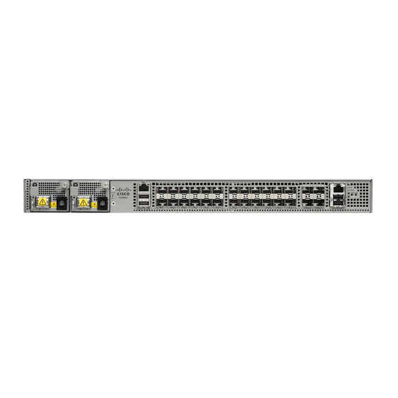
Overview Front and Back Panel Front and Back Panel The following figures show the port numbering for the Cisco ASR-920-24SZ-IM Router: Figure 6: Front Panel of Cisco ASR-920-24SZ-IM Router Power Supply 0 (AC or DC) 4x10GE SFP+ Power Supply 0 LED (AC or... -
Page 22: Cisco Asr-920-24Sz-Im, Asr-920-24Sz-M, Asr-920-24Tz-M Aggregation Services Router Hardware Installation
System Status LED 24x1GE SFP Fiber ports Board power LED Slot for ports on the interface module Figure 7: Back Panel of Cisco ASR-920-24SZ-IM Router Grounding lugs Fan status LED Cisco ASR-920-24SZ-IM, ASR-920-24SZ-M, ASR-920-24TZ-M Aggregation Services Router Hardware Installation Guide... -
Page 23: Cisco Asr-920-24Sz-Im, Asr-920-24Sz-M, Asr-920-24Tz-M Aggregation Services Router Hardware Installation
Power Supply 0 (AC or DC) 24x1GE SFP Fiber (Cisco ASR-920-24SZ-M) 24x1GE SFP Copper (Cisco ASR-920-24TZ-M) Power Supply 0 LED (AC or 4x10GE SFP+ Power Supply 1 (AC or DC) USB Memory port Cisco ASR-920-24SZ-IM, ASR-920-24SZ-M, ASR-920-24TZ-M Aggregation Services Router Hardware Installation Guide... -
Page 24: Specifications
Figure 9: Back Panel of Cisco ASR-920-24SZ-M, ASR-920-24TZ-M Router Grounding lugs Fan status LED Specifications The table below describes the other features of Cisco ASR-920-24SZ-IM Router (AC and DC) and Cisco ASR-920-24SZ-M, ASR-920-24TZ-M Router (AC and DC) Routers. Table 3: Cisco ASR 920-24SZ-IM, ASR-920-24SZ-M, ASR-920-24TZ-M Router Specifications Specification... -
Page 25: Cisco Asr-920-24Sz-Im, Asr-920-24Sz-M, Asr-920-24Tz-M Aggregation Services Router Hardware Installation
• 4 alarm dry contact inputs (normally open) (normally open) • LED indicators for critical, • LED indicators for critical, major and minor alarms major and minor alarms TDM Support Supported through IM card None Cisco ASR-920-24SZ-IM, ASR-920-24SZ-M, ASR-920-24TZ-M Aggregation Services Router Hardware Installation Guide... -
Page 26: External Interfaces
1 PPS and 10 M1588v2 and SyncE feature supported and SyncE feature supported External Interfaces The Cisco ASR 920-24SZ-IM, ASR-920-24SZ-M, ASR-920-24TZ-M Router have these external physical interfaces on the front panel: Network Interfaces The network interfaces are provided through fixed ports. -
Page 27: Network Timing Interfaces
• GPS 1 PPS input and output—1 PPS input for GPS Synchronization. This connector on the front panel can provide 1 PPS output as well from Cisco ASR-920-24SZ-IM Router. The direction can be configured using software. External Alarm Inputs The Cisco ASR 920-24SZ-IM, ASR-920-24SZ-M, ASR-920-24TZ-M Router supports four dry contact alarm inputs through an RJ-45 jack on the front panel. -
Page 28: Led Indicators
Note device. The Cisco ASR 920-24SZ-IM, ASR-920-24SZ-M, ASR-920-24TZ-M Router have removable fan tray as part of the system. The fan tray is hot-swappable. The system is designed to operate at its maximum operating temperature of 70º C and at 65º C in case of failure of a single fan, for a maximum of four hours. -
Page 29: Cisco Asr-920-24Sz-Im, Asr-920-24Sz-M, Asr-920-24Tz-M Aggregation Services Router Hardware Installation
Amber A minor alarm or — synchronization is in Holdover or free-running mode Green A major or critical alarm (high — temperature reported for any sensor) or multiple fan failure. Cisco ASR-920-24SZ-IM, ASR-920-24SZ-M, ASR-920-24TZ-M Aggregation Services Router Hardware Installation Guide... -
Page 30: Cpu Management Port Leds
Labeled same as the SFP port Green Link up in number 1000Base-X/100Base-FX Blinking Green Activity in 1000 Base-X/100Base-FX Yellow Fault/Error Link down SFP+ LEDs Each SFP+ port has an LED indicator. Cisco ASR-920-24SZ-IM, ASR-920-24SZ-M, ASR-920-24TZ-M Aggregation Services Router Hardware Installation Guide... -
Page 31: T1/E1 Interface Module Leds
Blinking amber One or more configured ports are down and at least one configured port is in a loopback state All ports disabled or shut down Cisco ASR-920-24SZ-IM, ASR-920-24SZ-M, ASR-920-24TZ-M Aggregation Services Router Hardware Installation Guide... -
Page 32: Rj-45 Leds
Link down Right Green Link up in full duplex Link up in half duplex Power Supply Unit LEDs Each power supply unit has a corresponding LED on the front panel. Cisco ASR-920-24SZ-IM, ASR-920-24SZ-M, ASR-920-24TZ-M Aggregation Services Router Hardware Installation Guide... -
Page 33: System-Interface Led Behavior
Management Port LEDs (Link/Duplex) ROMMON (cable connect) Green/Green (1000 Mbps, Full Duplex) Orange/Green (100/10 Mbps, Full Duplex) ROMMON (cable disconnect) Off/Off IOS Shut Off/Off IOS No shut (cable disconnect) Orange Off/Off Cisco ASR-920-24SZ-IM, ASR-920-24SZ-M, ASR-920-24TZ-M Aggregation Services Router Hardware Installation Guide... -
Page 34: Online Insertion And Removal
When a power supply is not working or the input cable is removed, the remaining power supply takes the entire load without disruption. • Except for TDM IM, you can hot-swap an interface module with a similar interface module on Cisco ASR-920-24SZ-IM Router. For more information, see Hot-Swapping the Interface Module section. -
Page 35: Licensing The Router
Cisco software feature sets by obtaining and validating fee-based Cisco software licenses. Licenses generated by the Cisco Software Licensing are tied to the UDI of the chassis and a corresponding Note watchtower device certificate (WDC) is stored in the system. -
Page 36: Cisco Asr-920-24Sz-Im, Asr-920-24Sz-M, Asr-920-24Tz-M Aggregation Services Router Hardware Installation
Overview External Interfaces Cisco ASR-920-24SZ-IM, ASR-920-24SZ-M, ASR-920-24TZ-M Aggregation Services Router Hardware Installation Guide... -
Page 37: Preparing For Installation
C H A P T E R Preparing for Installation This chapter describe how to prepare for the installation of the Cisco ASR 920-24SZ-IM, ASR-920-24SZ-M, ASR-920-24TZ-M Router at your site. • Safety Guidelines, page 25 • Site Planning, page 31 •... -
Page 38: Safety Guidelines For Personal Safety And Equipment Protection
1999/5/EC. Statement 287 For other standard warning messages and their translations, see the Regulatory Compliance and Safety Information for the Cisco ASR 920 Series Aggregation Services Router document. Safety Guidelines for Personal Safety and Equipment Protection The following guidelines help ensure your safety and protect the equipment. This list does not include all the potentially hazardous situations. -
Page 39: Safety Precautions For Module Installation And Removal
Be sure to observe the following safety precautions when you work on the router. To see the translations of the warnings that appear in this publication, see the Regulatory Compliance and Safety Information for the Cisco ASR 920 Series Router document. Warning Class 1 laser product. -
Page 40: Cisco Asr-920-24Sz-Im, Asr-920-24Sz-M, Asr-920-24Tz-M Aggregation Services Router Hardware Installation
Statement 1024 Use copper conductors only. Statement 1025 Warning This unit might have more than one power supply connection. All connections must be removed to Warning de-energize the unit. Statement 1028 Cisco ASR-920-24SZ-IM, ASR-920-24SZ-M, ASR-920-24TZ-M Aggregation Services Router Hardware Installation Guide... -
Page 41: Cisco Asr-920-24Sz-Im, Asr-920-24Sz-M, Asr-920-24Tz-M Aggregation Services Router Hardware Installation
Be sure uninsulated conductors are not accessible when cover is in place. Statement 1086 To see the safety with electricity, see the Regulatory Compliance and Safety Information for the Cisco ASR 920 Series Aggregation Services Router document. -
Page 42: Power Supply Considerations
These devices prevent accidental removal, provide proper grounding for the system, and help to ensure that bus connectors are properly seated. Cisco ASR-920-24SZ-IM, ASR-920-24SZ-M, ASR-920-24TZ-M Aggregation Services Router Hardware Installation Guide... -
Page 43: Site Planning
1 and 10 Mohm. Site Planning The sections describe how to plan for the installation of the Cisco ASR 920 Series Router. General Precautions Observe the following general precautions when using and working with your Cisco ASR 920-24SZ-IM, ASR-920-24SZ-M, ASR-920-24TZ-M Router: •... -
Page 44: Site Selection Guidelines
After installation, make sure that the site maintains the environmental characteristics described in Cisco ASR 920-24SZ-IM, ASR-920-24SZ-M, ASR-920-24TZ-M Router Specifications table. For an outside plant installation (cell site cabinet, hut etc.), it is required that the Cisco ASR 920-24SZ-IM, ASR-920-24SZ-M, ASR-920-24TZ-M Router be protected against airborne contaminants, dust, moisture, insects, pests, corrosive gases, polluted air or other reactive elements present in the outside air. -
Page 45: Physical Characteristics
Site Selection Guidelines Physical Characteristics Be familiar with the physical characteristics of the Cisco ASR 920-24SZ-IM, ASR-920-24SZ-M, ASR-920-24TZ-M Router to assist you in placing the system in the proper location. For more information, see Cisco ASR 920-24SZ-IM, ASR-920-24SZ-M, ASR-920-24TZ-M Router Specifications table. -
Page 46: Cisco Asr-920-24Sz-Im, Asr-920-24Sz-M, Asr-920-24Tz-M Aggregation Services Router Hardware Installation
Preparing for Installation Site Selection Guidelines The following figure shows the direction of the air flow through the Cisco ASR-920-24SZ-M, ASR-920-24TZ-M Router. Figure 11: Air Flow in the Cisco ASR-920-24SZ-M, ASR-920-24TZ-M Router To ensure adequate air flow through the equipment rack, it is recommended that you maintain a minimum clearance distance as mentioned below, at all times. -
Page 47: Cisco Asr-920-24Sz-Im, Asr-920-24Sz-M, Asr-920-24Tz-M Aggregation Services Router Hardware Installation
Also ensure that the device behind the Cisco ASR 920-24SZ-IM, ASR-920-24SZ-M, ASR-920-24TZ-M Routeris not installed in a way that t it blows air into the Cisco ASR 920-24SZ-IM, ASR-920-24SZ-M, ASR-920-24TZ-M Router. • If airflow through the equipment rack and the routers that occupy it is blocked or restricted, or if the ambient air being drawn into the rack is too warm, an overtemperature condition may occur within the rack and the routers that occupy it. -
Page 48: Air Flow Guidelines For Etsi Rack Installation
ASR-920-24TZ-M Routers is capable of supporting the combined weight of the rack and all the other installed equipment. To assess the weight of a fully configured Cisco ASR 920 Series Router, see the Cisco ASR 920-24SZ-IM, ASR-920-24SZ-M, ASR-920-24TZ-M Router Specifications table. -
Page 49: Electrical Circuit Requirements
(CSU), or data service units (DSU). Before you install the Cisco ASR 920-24SZ-IM, ASR-920-24SZ-M, ASR-920-24TZ-M Router, have all the additional external equipment and cables on hand. For information about ordering, contact a Cisco customer service representative. The extent of your network and the distances between the network interface connections depend, in part, on the following factors: •... -
Page 50: Asynchronous Terminal Connections
Lightning and AC Power Fault Interference If signal wires exceed the recommended cabling distances, or if signal wires pass between buildings, you should consider the effect that a lightning strike in your vicinity might have on the Cisco ASR 920-24SZ-IM, ASR-920-24SZ-M, ASR-920-24TZ-M Router. -
Page 51: Rack-Mounting Guidelines
Preparing for Installation Rack-Mounting Guidelines electrical surge suppression and shielding of signal cables in your Cisco ASR 920-24SZ-IM, ASR-920-24SZ-M, ASR-920-24TZ-M Router operating environment. Rack-Mounting Guidelines The sections provide guidelines for rack-mounting the Cisco ASR 920-24SZ-IM, ASR-920-24SZ-M, ASR-920-24TZ-M Router. Precautions for Rack-Mounting The following rack-mount guidelines are provided to ensure your safety: •... -
Page 52: Equipment Rack Guidelines
ASR-920-24SZ-M, ASR-920-24TZ-M Router by following the guidelines described here. Locating for Safety If the Cisco ASR 920-24SZ-IM, ASR-920-24SZ-M, ASR-920-24TZ-M Router is the heaviest or the only piece of equipment in the rack, consider installing it at or near the bottom to ensure that the rack’s center of gravity is as low as possible. -
Page 53: Locating For Proper Airflow
Use this to record the completion and verification of each procedure. After the checklist is completed, place it in your Site Log along with the other records pertaining to your new Cisco router. Table 15: Cisco ASR 920-24SZ-IM, ASR-920-24SZ-M, ASR-920-24TZ-M Router Installation Checklist... -
Page 54: Creating A Site Log
Create the Site Log prior to the installation. (See Site Log section for more information about the Site Log as well as a sample Site Log that can be used to make copies.) Cisco ASR-920-24SZ-IM, ASR-920-24SZ-M, ASR-920-24TZ-M Aggregation Services Router Hardware Installation Guide... -
Page 55: Receiving The Router
Preparing for Installation Receiving the Router Receiving the Router Each Cisco ASR 920-24SZ-IM, ASR-920-24SZ-M, ASR-920-24TZ-M Router chassis is shipped in a container that is strapped to a pallet, as illustrated in the following figures. Figure 12: Cisco ASR-920-24SZ-IM Router Packaged for Shipping... -
Page 56: Chassis-Lifting Guidelines
• Ensure that your footing is solid, and balance the weight of the chassis between your feet. • Lift the chassis slowly; never move suddenly or twist your body as you lift. Cisco ASR-920-24SZ-IM, ASR-920-24SZ-M, ASR-920-24TZ-M Aggregation Services Router Hardware Installation Guide... -
Page 57: Tools And Equipment
Only trained and qualified personnel should be allowed to install or replace this equipment. Statement 49 Warning Unpacking and Verifying the Shipped Contents When you receive your chassis, perform the following steps: Cisco ASR-920-24SZ-IM, ASR-920-24SZ-M, ASR-920-24TZ-M Aggregation Services Router Hardware Installation Guide... -
Page 58: Cisco Asr-920-24Sz-Im, Asr-920-24Sz-M, Asr-920-24Tz-M Aggregation Services Router Hardware Installation
Use the table below to check the contents of the Cisco ASR 920-24SZ-IM, ASR-920-24SZ-M, ASR-920-24TZ-M Router shipping container. Do not discard the shipping container. You will need the container if you move or ship the Cisco ASR 920-24SZ-IM, ASR-920-24SZ-M, ASR-920-24TZ-M Router in the future. -
Page 59: Cisco Asr-920-24Sz-Im, Asr-920-24Sz-M, Asr-920-24Tz-M Aggregation Services Router Hardware Installation
Preparing for Installation Unpacking and Verifying the Shipped Contents Cisco ASR-920-24SZ-IM, ASR-920-24SZ-M, ASR-920-24TZ-M Aggregation Services Router Hardware Installation Guide... -
Page 60: Cisco Asr-920-24Sz-Im, Asr-920-24Sz-M, Asr-920-24Tz-M Aggregation Services Router Hardware Installation
Preparing for Installation Unpacking and Verifying the Shipped Contents Cisco ASR-920-24SZ-IM, ASR-920-24SZ-M, ASR-920-24TZ-M Aggregation Services Router Hardware Installation Guide... -
Page 61: Installing The Router
• Gathering the tools and test equipment required to properly install the Cisco ASR 920-24SZ-IM, ASR-920-24SZ-M, ASR-920-24TZ-M Router. See Tools and Equipment section. For more instructions on how to prepare for the installation of the Cisco ASR 920-24SZ-IM, ASR-920-24SZ-M, ASR-920-24TZ-M Router, see Chapter 2, Preparing for Installation. -
Page 62: Installing The Router In A Rack
The following figures show how to attach the brackets at the front, middle, and rear positions on the Cisco ASR-920-24SZ-IM Router for a 19-inch EIA rack. Figure 14: Attaching Mounting Brackets to Cisco ASR-920-24SZ-IM Router for a 19-inch EIA Rack (Front, Middle, and Rear Positions) Cisco ASR-920-24SZ-IM, ASR-920-24SZ-M, ASR-920-24TZ-M Aggregation Services Router Hardware Installation... -
Page 63: Cisco Asr-920-24Sz-Im, Asr-920-24Sz-M, Asr-920-24Tz-M Aggregation Services Router Hardware Installation
Installing the Router Installing the Chassis Brackets The following figures show how to attach the brackets at the front, middle, and rear positions on the Cisco ASR-920-24SZ-M, ASR-920-24TZ-M Router for a 19-inch EIA rack. Figure 15: Attaching Mounting Brackets to Cisco ASR-920-24SZ-M, ASR-920-24TZ-M Router for a 19-inch EIA Rack (Front, Middle,... -
Page 64: Cisco Asr-920-24Sz-Im, Asr-920-24Sz-M, Asr-920-24Tz-M Aggregation Services Router Hardware Installation
Installing the Chassis Brackets 23-inch Rack The following figures show how to attach the brackets on the Cisco ASR-920-24SZ-IM Router for a 23-inch rack. Figure 16: Attaching Mounting Brackets to Cisco ASR-920-24SZ-IM Router for a 23-inch Rack (Front, Middle, and Rear Positions) -
Page 65: Cisco Asr-920-24Sz-Im, Asr-920-24Sz-M, Asr-920-24Tz-M Aggregation Services Router Hardware Installation
Installing the Router Installing the Chassis Brackets The following figures shows how to attach the brackets on the Cisco ASR-920-24SZ-M, ASR-920-24TZ-M Router for a 23-inch rack. Figure 17: Attaching Mounting Brackets to Cisco ASR-920-24SZ-M, ASR-920-24TZ-M Routerfor a 23-inch Rack (Front, Middle, and... -
Page 66: Cisco Asr-920-24Sz-Im, Asr-920-24Sz-M, Asr-920-24Tz-M Aggregation Services Router Hardware Installation
300-mm ETSI Rack The following figures show how to attach the brackets on the Cisco ASR-920-24SZ-IM Router for a 300 mm ETSI rack. Figure 18: Attaching Mounting Brackets to Cisco ASR-920-24SZ-IM Router for a 300 mm ETSI Rack (Front, Middle, and Rear Positions) -
Page 67: Cisco Asr-920-24Sz-Im, Asr-920-24Sz-M, Asr-920-24Tz-M Aggregation Services Router Hardware Installation
The following figures show how to attach the brackets on the Cisco ASR-920-24SZ-M, ASR-920-24TZ-M Router for a 300 mm ETSI rack. Figure 19: Attaching Mounting Brackets to Cisco ASR-920-24SZ-M, ASR-920-24TZ-M Router for a 300 mm ETSI Rack (Front, Middle, and Rear Positions) -
Page 68: Installing The Router Chassis In The Rack
3. Install the four M6x12mm zinc-plated steel screws through the holes in the bracket and into the threaded holes in the equipment rack posts. 4. Use a tape measure and level to verify that the chassis is installed straight and level. Cisco ASR-920-24SZ-IM, ASR-920-24SZ-M, ASR-920-24TZ-M Aggregation Services Router Hardware Installation Guide... -
Page 69: Cisco Asr-920-24Sz-Im, Asr-920-24Sz-M, Asr-920-24Tz-M Aggregation Services Router Hardware Installation
• If the rear of the chassis is at the front of the rack, insert the front of the chassis between the mounting posts. Step 2 Align the mounting holes in the bracket (and optional cable guide) with the mounting holes in the equipment rack. Cisco ASR-920-24SZ-IM, ASR-920-24SZ-M, ASR-920-24TZ-M Aggregation Services Router Hardware Installation Guide... -
Page 70: Cisco Asr-920-24Sz-Im, Asr-920-24Sz-M, Asr-920-24Tz-M Aggregation Services Router Hardware Installation
Installing the Router Installing the Router Chassis in the Rack The following figures show how to install the Cisco ASR-920-24SZ-IM Router in a 19-inch EIA rack. Figure 20: Installing the Cisco ASR-920-24SZ-IM Router in a 19-inch EIA Rack Figure 21: Installing the Cisco ASR-920-24SZ-M, ASR-920-24TZ-M Router in a 19-inch EIA Rac... -
Page 71: Attaching The Cable Guides
Use a tape measure and level to verify that the chassis is installed straight and level. Attaching the Cable Guides The Cisco ASR-920-24SZ-IM Router supports the following cable guides: • A920-CBL-GUIDE (left and right)—help in routing the cables from all components on the front panel thereby enabling a proper cable-bending radius. -
Page 72: Cisco Asr-920-24Sz-Im, Asr-920-24Sz-M, Asr-920-24Tz-M Aggregation Services Router Hardware Installation
19-inch rack and in the figure for other racks using standard kit. Figure 22: Cable Guide Installation On Cisco ASR-920-24SZ-IM Router For 19-inch Rack Brackets Figure 23: Installing the Cable Guides on Cisco ASR-920-24SZ-IM Router (As Per the Standard Kit) Cisco ASR-920-24SZ-IM, ASR-920-24SZ-M, ASR-920-24TZ-M Aggregation Services Router Hardware Installation... -
Page 73: Wall Mounting The Routers
Secure the cable guides with the four M6x12mm screws supplied with the cable kit. The recommended maximum torque is 3N-m. Wall Mounting the Routers This section shows the procedures to install the Cisco ASR 920-24SZ-IM, ASR-920-24SZ-M, ASR-920-24TZ-M Router on a wall. Cisco ASR-920-24SZ-IM, ASR-920-24SZ-M, ASR-920-24TZ-M Aggregation Services Router Hardware Installation... -
Page 74: Attaching The Brackets To The Router For Wall-Mounting
Attaching the Brackets to the Router for Wall-Mounting Attaching the Brackets to the Router for Wall-Mounting The following figure shows how to attach a 19-inch bracket to the Cisco ASR-920-24SZ-M, ASR-920-24TZ-M Router. Figure 24: Attaching 19-inch Brackets on Cisco ASR-920-24SZ-M, ASR-920-24TZ-M Router for Wall Mounting... -
Page 75: Cisco Asr-920-24Sz-Im, Asr-920-24Sz-M, Asr-920-24Tz-M Aggregation Services Router Hardware Installation
3. Tighten the four screws to affix the drip tray to the wall. DETAILED STEPS Step 1 Mount the router with the front panel as shown in the following figures. Cisco ASR-920-24SZ-IM, ASR-920-24SZ-M, ASR-920-24TZ-M Aggregation Services Router Hardware Installation Guide... -
Page 76: Cisco Asr-920-24Sz-Im, Asr-920-24Sz-M, Asr-920-24Tz-M Aggregation Services Router Hardware Installation
Installing the Router Mounting Routers on the Wall The following figures show the wall installation of Cisco ASR-920-24SZ-IM Router and the wall installation of Cisco ASR-920-24SZ-M, ASR-920-24TZ-M Router. Figure 25: Mounting the Cisco ASR-920-24SZ-IM Router on the Wall Drip tray for Cisco ASR-920-24SZ-IM Router... -
Page 77: Cisco Asr-920-24Sz-Im, Asr-920-24Sz-M, Asr-920-24Tz-M Aggregation Services Router Hardware Installation
When mounting the Cisco ASR 920-24SZ-IM, ASR-920-24SZ-M, ASR-920-24TZ-M Router vertically, Caution ensure that the power supplies are at the bottom. When mounting the ASR-920-24SZ-1M to a wall, you must install the drip tray (Cisco part number Caution 700-47267-01) as shown below to meet IEC 60950-1 product safety requirements. -
Page 78: Installing And Removing The Interface Module
Installing and Removing the Interface Module Installing and Removing the Interface Module The sections describe the installation and removal of interface module on the Cisco ASR-920-24SZ-IM Router. Installing the Interface Module Before installing the interface module, read the Activating or Deactivating Interface Module section in... -
Page 79: Cisco Asr-920-24Sz-Im, Asr-920-24Sz-M, Asr-920-24Tz-M Aggregation Services Router Hardware Installation
Carefully slide the interface module into the router slot until the interface module makes contact with the backplane. The following figure shows how to install the interface module on Cisco ASR-920-24SZ-IM Router. Figure 27: Inserting an Interface Module on Cisco ASR-920-24SZ-IM Router Step 5 Tighten the locking thumbscrews on both sides of the interface module. -
Page 80: Removing The Interface Module
Slide the interface module out of the router slot by pulling on the handles.If you are removing a blank filler plate, pull the blank filler plate completely out of the router slot using the captive screws. Cisco ASR-920-24SZ-IM, ASR-920-24SZ-M, ASR-920-24TZ-M Aggregation Services Router Hardware Installation Guide... -
Page 81: Hot-Swapping The Interface Module
Hot-Swapping the Interface Module Note If the interface module slot is to remain empty, install a blank filler plate (Cisco part number 800-35323-01) over the opening, and secure it with captive installation screws. Figure 28: Removing an Interface Module from Cisco ASR-920-24SZ-IM Router... -
Page 82: Installing And Removing The Fan Tray
Installing the Router Installing and Removing the Fan Tray The Cisco ASR-920-24SZ-IM Router does not support hot-swapping or OIR of TDM IM. To activate a Caution TDM IM you must reload the router. Without reloading the router, the IM or associated front panel ports cannot be used. -
Page 83: Cisco Asr-920-24Sz-Im, Asr-920-24Sz-M, Asr-920-24Tz-M Aggregation Services Router Hardware Installation
DETAILED STEPS Step 1 Guide the fan tray into the chassis until it is fully seated. The following figures show how to orient the fan tray for Cisco ASR-920-24SZ-IM Router and Cisco ASR-920-24SZ-M, ASR-920-24TZ-M Router respectively. Keep your fingers, clothing, and jewelry away from the fans. Always handle the fan tray by the handle. -
Page 84: Cisco Asr-920-24Sz-Im, Asr-920-24Sz-M, Asr-920-24Tz-M Aggregation Services Router Hardware Installation
Secure the fan tray to the chassis using the attached captive installation screws. The recommended maximum torque is 5.5 in.-lb (.62 N-m). Figure 29: Installing the Fan Tray on Cisco ASR-920-24SZ-IM Router Figure 30: Installing the Fan Tray on Cisco ASR-920-24SZ-M, ASR-920-24TZ-M Router... -
Page 85: Removing The Fan Tray
For more information about air flow guidelines, see the Air Flow Guidelines section. Removing the Fan Tray The fan tray supports online insertion and removal (OIR). There is no need to power down the Cisco ASR 920-24SZ-IM, ASR-920-24SZ-M, ASR-920-24TZ-M Router to remove or replace the fan tray. However, the router will shut down if the fan tray is removed from the chassis for more than five minutes. -
Page 86: Cisco Asr-920-24Sz-Im, Asr-920-24Sz-M, Asr-920-24Tz-M Aggregation Services Router Hardware Installation
1. Using a No. 2 Phillips screwdriver or your fingers, loosen the captive installation screws that secures the fan tray to the chassis. Figure 3-18 shows the front of the Cisco ASR-920-24SZ-IM Router fan tray, including the captive installation screws. Figure 3-19 shows the front of the Cisco ASR-920-24SZ-M, ASR-920-24TZ-M Router fan tray, including the captive installation screws. -
Page 87: Cisco Asr-920-24Sz-Im, Asr-920-24Sz-M, Asr-920-24Tz-M Aggregation Services Router Hardware Installation
Installing the Router Removing the Fan Tray screws. Figure 3-19 shows the front of the Cisco ASR-920-24SZ-M, ASR-920-24TZ-M Router fan tray, including the captive installation screws. Figure 31: Removing the Fan Tray From Cisco ASR-920-24SZ-IM Router Figure 32: Removing the Fan Tray From Cisco ASR-920-24SZ-M, ASR-920-24TZ-M Route... -
Page 88: Installing The Power Supply
To install a new fan tray, follow the steps in the Installing the Fan Tray section. Installing the Power Supply The Cisco ASR 920-24SZ-IM, ASR-920-24SZ-M, ASR-920-24TZ-M Router provides the choice of two different power supplies: • DC power—-48 V/60 Vdc or 24 Vdc The DC power supply uses 2 position terminal block-style connector. -
Page 89: Preventing Power Loss
• In some systems, you can use an UPS to protect against power failures at your site. Avoid UPS types that use ferroresonant technology. These UPS types can become unstable with systems such as the Cisco ASR 920-24SZ-IM, ASR-920-24SZ-M, ASR-920-24TZ-M Router, which can have substantial current-draw fluctuations due to bursty data traffic patterns. -
Page 90: Guidelines For Dc-Powered Systems
Installing a DC Power Supply The sections describe how to install a DC power supply in the Cisco ASR 920-24SZ-IM, ASR-920-24SZ-M, ASR-920-24TZ-M Router: Note This equipment is suitable for installation in Network Telecommunications Facilities and locations where the NEC applies. -
Page 91: Installing A Dc Power Supply Module
Slide the power supply into the power supply bay as shown in the figure below. Make sure that the power supply is fully seated in the bay. 5. Tighten the captive installation screw of the power supply. The recommended maximum torque is 5.5 in.-lb (.62 N-m). Cisco ASR-920-24SZ-IM, ASR-920-24SZ-M, ASR-920-24TZ-M Aggregation Services Router Hardware Installation Guide... -
Page 92: Attaching Cables To The Dc Power Supply
Attaching Cables to the DC Power Supply Note When installing DC power supply, use 14 AWG, 90°C wires. Always ensure that the building’s installation for short-circuit (overcurrent) protection does not exceed 15A. Cisco ASR-920-24SZ-IM, ASR-920-24SZ-M, ASR-920-24TZ-M Aggregation Services Router Hardware Installation Guide... -
Page 93: Cisco Asr-920-24Sz-Im, Asr-920-24Sz-M, Asr-920-24Tz-M Aggregation Services Router Hardware Installation
Step 2 Attach the DC supply wires in the designated screws. See the figure below. Figure 34: Connecting the DC Power Supply Wires Step 3 Close the DC power supply guard. Cisco ASR-920-24SZ-IM, ASR-920-24SZ-M, ASR-920-24TZ-M Aggregation Services Router Hardware Installation Guide... -
Page 94: Powering On The Router
Connect the front-panel ports. See the Connecting to SFP Modules section to complete the installation. Removing and Replacing a DC Power Supply This section provides information about removing and replacing a DC power supply in the Cisco ASR 920-24SZ-IM, ASR-920-24SZ-M, ASR-920-24TZ-M Router. -
Page 95: Cisco Asr-920-24Sz-Im, Asr-920-24Sz-M, Asr-920-24Tz-M Aggregation Services Router Hardware Installation
7. Replace the DC power supply within 5 minutes. See Installing a DC Power Supply figure. If the power supply bay is to remain empty, install a blank filler plate (Cisco part number 800-39165-01) over the opening, and secure it with captive installation screws. -
Page 96: Installing An Ac Power Supply
Replace the DC power supply within 5 minutes. See Installing a DC Power Supply figure. If the power supply bay is to remain empty, install a blank filler plate (Cisco part number 800-39165-01) over the opening, and secure it with captive installation screws. -
Page 97: Installing An Ac Power Supply Module
Slide the power supply into the power supply bay. Make sure that the power supply is fully seated in the bay. 4. Tighten the captive installation screw of the power supply. The recommended maximum torque is 5.5 in.-lb (.62 N-m). Cisco ASR-920-24SZ-IM, ASR-920-24SZ-M, ASR-920-24TZ-M Aggregation Services Router Hardware Installation Guide... -
Page 98: Activating An Ac Power Supply
Tighten the captive installation screw of the power supply. The recommended maximum torque is 5.5 in.-lb (.62 N-m). Power supply captive installation screws must be tight to ensure protective grounding continuity. Statement Warning Activating an AC Power Supply Follow these steps to activate an AC power supply: Cisco ASR-920-24SZ-IM, ASR-920-24SZ-M, ASR-920-24TZ-M Aggregation Services Router Hardware Installation Guide... -
Page 99: Cisco Asr-920-24Sz-Im, Asr-920-24Sz-M, Asr-920-24Tz-M Aggregation Services Router Hardware Installation
7. If you are installing a redundant power supply, repeat these steps for the second power source. DETAILED STEPS Step 1 Attach the AC power retainer cord as shown in the figure below. Figure 38: Attaching the AC Power Retainer Cord Cisco ASR-920-24SZ-IM, ASR-920-24SZ-M, ASR-920-24TZ-M Aggregation Services Router Hardware Installation Guide... -
Page 100: Cisco Asr-920-24Sz-Im, Asr-920-24Sz-M, Asr-920-24Tz-M Aggregation Services Router Hardware Installation
If you are installing a redundant AC power supply, ensure that each power supply is connected to a separate Note power source in order to prevent power loss in the event of a power failure. Cisco ASR-920-24SZ-IM, ASR-920-24SZ-M, ASR-920-24TZ-M Aggregation Services Router Hardware Installation Guide... -
Page 101: Removing And Replacing An Ac Power Supply
5. Replace the AC power supply within 5 minutes. See Installing the AC Power Supply figure. If the power supply bay is to remain empty, install a blank filler plate (Cisco part number 800-39165-01) over the opening, and secure it with captive installation screws. -
Page 102: Installing And Removing Sfp Modules
Replace the AC power supply within 5 minutes. See Installing the AC Power Supply figure. If the power supply bay is to remain empty, install a blank filler plate (Cisco part number 800-39165-01) over the opening, and secure it with captive installation screws. -
Page 103: Installing Sfp Modules
4. Insert the SFP module into the slot until you feel the connector on the module snap into place in the rear of the slot. See Installing an SFP Module with a Bale-Clasp Latch into an SFP Module Slot on Cisco ASR... -
Page 104: Cisco Asr-920-24Sz-Im, Asr-920-24Sz-M, Asr-920-24Tz-M Aggregation Services Router Hardware Installation
Insert the SFP module into the slot until you feel the connector on the module snap into place in the rear of the slot. See Installing an SFP Module with a Bale-Clasp Latch into an SFP Module Slot on Cisco ASR 920-24SZ-IM, ASR-920-24SZ-M,... -
Page 105: Cisco Asr-920-24Sz-Im, Asr-920-24Sz-M, Asr-920-24Tz-M Aggregation Services Router Hardware Installation
Bale-Clasp Latch into an SFP Module Slot on Cisco ASR 920-24SZ-IM, ASR-920-24SZ-M, ASR-920-24TZ-M Router figure for installing SFP Module without a Bale-Clasp Latch. Figure 42: Installing an SFP Module with a Bale-Clasp Latch into an SFP Module Slot on Cisco ASR 920-24SZ-IM, ASR-920-24SZ-M, ASR-920-24TZ-M Router... -
Page 106: Removing Sfp Modules
Disconnect the cable from the SFP module, and insert a dust plug into the cable end. For reattachment, note which cable connector plug is send (TX) and which is receive (RX). Cisco ASR-920-24SZ-IM, ASR-920-24SZ-M, ASR-920-24TZ-M Aggregation Services Router Hardware Installation Guide... -
Page 107: Cisco Asr-920-24Sz-Im, Asr-920-24Sz-M, Asr-920-24Tz-M Aggregation Services Router Hardware Installation
Figure 44: Removing a SFP Module with Bale-Clasp Latch From Cisco ASR 920-24SZ-IM, ASR-920-24SZ-M, ASR-920-24TZ-M Router Figure 45: Removing a SFP Module without Bale-Clasp Latch From Cisco ASR 920-24SZ-IM, ASR-920-24SZ-M, ASR-920-24TZ-M Router SFP module without Bale-Clasp Latch—Use the extraction tool to remove the SFP by inserting the tool into the side of... -
Page 108: Connecting To The 10/100/1000 Ports
If the port LED does not turn on, the device at the other end might not be turned on, or there might be a cable problem or a problem with the adapter installed in the attached device. Note On user network interface (UNI) ports, the port LED is green after the link is established. Cisco ASR-920-24SZ-IM, ASR-920-24SZ-M, ASR-920-24TZ-M Aggregation Services Router Hardware Installation Guide... -
Page 109: Connecting To Sfp Modules
If the LED is off, the target device might not be turned on, there might be a cable problem, or there might be problem with the adapter installed in the target device. Cisco ASR-920-24SZ-IM, ASR-920-24SZ-M, ASR-920-24TZ-M Aggregation Services Router Hardware Installation Guide... -
Page 110: Installing The Chassis Ground Connection
If necessary, reconfigure and restart the router or target device. Installing the Chassis Ground Connection Before you connect the power or turn on the power to the Cisco ASR-920-24SZ-IM Router, you must provide an adequate chassis ground (earth) connection to your router. -
Page 111: Cisco Asr-920-24Sz-Im, Asr-920-24Sz-M, Asr-920-24Tz-M Aggregation Services Router Hardware Installation
This unit is to be installed in a restrictive access location and must be permanently grounded to a minimum 6-AWG copper ground wire. Perform the following procedure to ground the Cisco ASR 920-24SZ-IM, ASR-920-24SZ-M, ASR-920-24TZ-M Router using a 2-hole lug and the corresponding mounting point. Most carriers require a minimum 6-AWG ground connection. -
Page 112: Power Connection Guidelines
Connect the other end of the ground wire to a suitable grounding point at your site. Power Connection Guidelines This section provides guidelines for connecting the Cisco ASR 920 Series Aggregation Services Router power supplies to the site power source. -
Page 113: Guidelines For Dc-Powered Systems
Preventing Power Loss Use the following guidelines to prevent power loss to the router: Cisco ASR-920-24SZ-IM, ASR-920-24SZ-M, ASR-920-24TZ-M Aggregation Services Router Hardware Installation Guide... -
Page 114: Activating A Dc Power Supply
Use the information in the Cisco ASR 920-24SZ-IM, ASR-920-24SZ-M, ASR-920-24TZ-M Router Specifications table to estimate the power requirements and heat dissipation of a Cisco ASR 920 Series Router based on a given configuration of the router. Determining power requirements is useful for planning the power distribution system needed to support the router. -
Page 115: Connecting A Router To The Network
Note Router ports. Connecting Console Cables The sections describe how to connect to the Cisco ASR 920-24SZ-IM, ASR-920-24SZ-M, ASR-920-24TZ-M Router using console cables: Connecting to the USB Serial Port Using Microsoft Windows This procedure shows how to connect to the USB serial port using Microsoft Windows. -
Page 116: Cisco Asr-920-24Sz-Im, Asr-920-24Sz-M, Asr-920-24Tz-M Aggregation Services Router Hardware Installation
• 9600 baud • 8 data bits • no parity • 1 stop-bit • no flow control Figure 50: Connecting the USB Console Cable to the Cisco ASR 920-24SZ-IM, ASR-920-24SZ-M, ASR-920-24TZ-M Router Cisco ASR-920-24SZ-IM, ASR-920-24SZ-M, ASR-920-24TZ-M Aggregation Services Router Hardware Installation Guide... -
Page 117: Connecting To The Console Port Using Mac Os X
Connect to the USB port with the following command followed by the router USB port speed: Example: macbook:user$ screen /dev/tty.usbmodem1411 9600 To disconnect the OS X USB console from the terminal window, enter Ctrl-a followed by Ctrl-\ Cisco ASR-920-24SZ-IM, ASR-920-24SZ-M, ASR-920-24TZ-M Aggregation Services Router Hardware Installation Guide... -
Page 118: Connecting To The Console Port Using Linux
Tools and Resources Download Software site, USB Console Software category, at: https://software.cisco.com/download/ release.html?mdfid=286037604&flowid=71056&softwareid=282855122&release=3.13&relind=A V AILABLE&rellifecycle=&reltype=latest Note To Download the driver, you must have a valid service contract associated to your Cisco.com profile. Cisco ASR-920-24SZ-IM, ASR-920-24SZ-M, ASR-920-24TZ-M Aggregation Services Router Hardware Installation Guide... -
Page 119: Uninstalling The Cisco Usb Device Driver
1. Choose Start > Control Panel > Add or Remove Programs (Uninstall a program). 2. Scroll to Windows Driver Package - Exar corporation (xrusbser) Ports and click Remove. The Program Maintenance window is displayed. 3. Click Yes to uninstall the driver. Cisco ASR-920-24SZ-IM, ASR-920-24SZ-M, ASR-920-24TZ-M Aggregation Services Router Hardware Installation Guide... -
Page 120: Connecting To The Eia Console Port
Click Yes to uninstall the driver. Connecting to the EIA Console Port The US-to-RJ45 adapter cable and the DB9 console cable are not included with the Cisco ASR Note 920-24SZ-IM, ASR-920-24SZ-M, ASR-920-24TZ-M Router; they can be ordered separately from Cisco. -
Page 121: Cisco Asr-920-24Sz-Im, Asr-920-24Sz-M, Asr-920-24Tz-M Aggregation Services Router Hardware Installation
Step 2 Connect the RJ-45 end of the DB-9 adapter cable to the USB-to RJ-45 cable, as shown in the figure below. Figure 51: Connecting a Modem to the Cisco ASR 920-24SZ-IM, ASR-920-24SZ-M, ASR-920-24TZ-M Router EIA Console port USB-to-RJ-45 adapter... -
Page 122: Connecting A Management Ethernet Cable
We recommend that you wait for 30 seconds between the removal and insertion of an SFP on an interface module. We recommend this to allow the transceiver software to initialize and synchronize with the Cisco ASR 920-24SZ-IM, ASR-920-24SZ-M, ASR-920-24TZ-M Router. Changing an SFP quicker could result in transceiver initialization issues that disable the SFP. -
Page 123: Removing A Usb Flash Device
Pull the memory stick from the USB port. Step 2 To replace the Cisco USB Flash memory stick, simply insert the module into the USB port labeled USB MEM, as shown in Cisco ASR 920-24SZ-IM, ASR-920-24SZ-M, ASR-920-24TZ-M Router Flash Token Memory Stick figure. The Flash memory module can be inserted only one way, and can be inserted or removed regardless of whether the router is powered up or not. -
Page 124: Connecting Cables To The Gps Interface
OSP wiring. Statement Connecting Cables to the GPS Interface The sections describe how to connect cables from the Cisco ASR-920-24SZ-IM Router to a GPS unit for input or output timing of frequency:... -
Page 125: Connecting A Cable To The Output 10-Mhz Or 1-Pps Interface
Connect one end of a shielded mini-coax cable to the GPS unit. Step 2 Connect the other end of the shielded mini-coax cable to the 10-Mhz or 1-PPS port on the RSP of the Cisco ASR-920-24SZ-IM Router. Connecting a Cable to the Output 10-Mhz or 1-PPS Interface SUMMARY STEPS 1. -
Page 126: Connecting Ethernet Cables
The RJ-45 port supports standard straight-through and crossover Category 5 unshielded twisted-pair (UTP) cables. Cisco does not supply Category 5 UTP cables; these cables are available commercially. To comply with the Telcordia GR-1089 NEBS standard for electromagnetic compatibility and safety, Warning connect the Gigabit Ethernet ports only to intra-building or unexposed wiring or cable. -
Page 127: Connecting Cables To Sfp Modules
Installing the Router Connecting Cables to SFP Modules Connecting Cables to SFP Modules For information on connecting cables to Cisco optical and Ethernet SFP interfaces, see: http://www.cisco.com/en/US/partner/products/hw/modules/ps5455/prod_installation_guides_list.html. Connector and Cable Specifications For more information on cable specifications and pinouts, see the Troubleshooting section. -
Page 128: Cisco Asr-920-24Sz-Im, Asr-920-24Sz-M, Asr-920-24Tz-M Aggregation Services Router Hardware Installation
Installing the Router Connector and Cable Specifications Cisco ASR-920-24SZ-IM, ASR-920-24SZ-M, ASR-920-24TZ-M Aggregation Services Router Hardware Installation Guide... -
Page 129: Initial Configuration
Complex configuration procedures are beyond the scope of this publication and can be found in the modular configuration and modular command reference publications in the Cisco IOS software configuration documentation set that corresponds to the software release installed on your Cisco hardware. To configure a Cisco ASR 920-24SZ-IM, ASR-920-24SZ-M, ASR-920-24TZ-M Router from a console, connect a terminal to the router console port. -
Page 130: Powering Up The Router
It takes a few minutes for the messages to stop. Step 2 Observe the initialization process. When the system boot is complete (the process can take a few minutes), the Cisco ASR 920-24SZ-IM, ASR-920-24SZ-M, ASR-920-24TZ-M Router begins to initialize. -
Page 131: Powering Up The Router
If you are unable to comply with U.S. and local laws, return this product immediately. A summary of U.S. laws governing Cisco cryptographic products may be found at: http://www.cisco.com/wwl/export/crypto/tool/stqrg.html If you require further assistance please contact us by sending email to export@cisco.com. -
Page 132: Powering Up The Router
*Sep 25 23:33:40.473: %LINK-3-UPDOWN: Interface GigabitEthernet0/0/8, changed state to down *Sep 25 23:33:40.521: %LINK-3-UPDOWN: Interface GigabitEthernet0/0/9, changed state to down *Sep 25 23:33:40.569: %LINK-3-UPDOWN: Interface GigabitEthernet0/0/10, changed state to down Cisco ASR-920-24SZ-IM, ASR-920-24SZ-M, ASR-920-24TZ-M Aggregation Services Router Hardware Installation Guide... -
Page 133: Verifying The Front Panel Leds
• show version—Displays the system hardware version, the installed software version, the names and sources of configuration files, the boot images, and the amount of installed DRAM, NVRAM, and flash memory. Cisco ASR-920-24SZ-IM, ASR-920-24SZ-M, ASR-920-24TZ-M Aggregation Services Router Hardware Installation Guide... -
Page 134: Checking Hardware And Software Compatibility
To configure a Cisco ASR 920-24SZ-IM, ASR-920-24SZ-M, ASR-920-24TZ-M Router from the console, you must connect a terminal or terminal server to the console port on the Cisco ASR 920-24SZ-IM, ASR-920-24SZ-M, ASR-920-24TZ-M Router. To configure the Cisco ASR 920-24SZ-IM, ASR-920-24SZ-M, ASR-920-24TZ-M Router using the management Ethernet port, you must have the router’s IP address. - Page 135 You now have access to the CLI in the privileged EXEC mode. You can enter the necessary commands to complete the required tasks. Step 5 To exit the console session, enter the quit command, as shown in the following example: Example: Router# quit Cisco ASR-920-24SZ-IM, ASR-920-24SZ-M, ASR-920-24TZ-M Aggregation Services Router Hardware Installation Guide...
-
Page 136: Configuring Global Parameters
Default settings are in square brackets '[]'. Basic management setup configures only enough connectivity for management of the system, extended setup will ask you to configure each interface on the system. Cisco ASR-920-24SZ-IM, ASR-920-24SZ-M, ASR-920-24TZ-M Aggregation Services Router Hardware Installation Guide... -
Page 137: Checking The Running Configuration Settings
Safely Powering Off the Router This section explains how to shut down the Cisco ASR 920-24SZ-IM, ASR-920-24SZ-M, ASR-920-24TZ-M Router. We recommend that before turning off all power to the chassis, you issue the reload command. This ensures that the operating system cleans up all the file systems. -
Page 138: Automatic Shutdown Of The Router
UEA platform with 2097152 Kbytes of main memory Step 5 Remove power cables, if any, from the Cisco ASR 920-24SZ-IM, ASR-920-24SZ-M, ASR-920-24TZ-M Router: • For power supplies with a circuit breaker switch, position the switch to the Off (O) position. -
Page 139: Troubleshooting
C H A P T E R Troubleshooting This chapter provides information about troubleshooting issues, if any, on the Cisco ASR 920-24SZ-IM, ASR-920-24SZ-M, ASR-920-24TZ-M Router: • Pinouts, page 127 Pinouts The sections describe the pinouts for the Cisco ASR 920-24SZ-IM, ASR-920-24SZ-M, ASR-920-24TZ-M Router interfaces. -
Page 140: Gps Port Pinout
Note GPS port is supported only on Cisco ASR-920-24SZ-IM Router. The 10 Mhz and 1 PPS interfaces can be configured as input or output using Cisco IOS CLI commands. Note For more information, see the Cisco ASR 920 Series Aggregation Services Router Configuration Guide. -
Page 141: Alarm Port Pinouts
Signal Name Description ALARM0_IN Alarm input 0 ALARM1_IN Alarm input 1 — No connect ALARM2_IN Alarm input 2 ALARM3_IN Alarm input 3 — No connect — No connect COMMON Alarm common Cisco ASR-920-24SZ-IM, ASR-920-24SZ-M, ASR-920-24TZ-M Aggregation Services Router Hardware Installation Guide... -
Page 142: Management Ethernet Port Pinouts
Table 22: Single USB Console Port Pinouts Signal Name Description +5VDC Data - Data + Ground The USB console port +5VDC is input, and operates as an USB peripheral device. Note Cisco ASR-920-24SZ-IM, ASR-920-24SZ-M, ASR-920-24TZ-M Aggregation Services Router Hardware Installation Guide... -
Page 143: Usb Flash Or Mem Port Pinouts
Data + Ground USB TYPE-A receptacle is used. Note The USB flash or MEM port +5VDC is output. Cisco ASR 920-24SZ-IM, ASR-920-24SZ-M, Note ASR-920-24TZ-M Router provides power for USB flash or MEM port. This port operates as a USB host device. -
Page 144: Optical Fiber Specifications
Within the multimode category, only short reach is available. For information about optical SFP modules, see the documentation for the SFP module at: http://www.cisco.com/en/US/partner/products/hw/modules/ps5455/prod_installation_guides_list.html Alarm Conditions The table below summarizes the meaning of the alarm conditions on the Cisco ASR 920-24SZ-IM, ASR-920-24SZ-M, ASR-920-24TZ-M Router. Table 25: Alarm Condition Summary Alarm Type... -
Page 145: Site Log
• Upgrade, removal, and maintenance procedures—Use the Site Log as a record of ongoing router maintenance and expansion history. Each time a task is performed on the Cisco ASR 920-24SZ-IM, ASR-920-24SZ-M, ASR-920-24TZ-M Router, update the Site Log to reflect the following: ◦... - Page 146 Site Log Date Description of Action Performed or Initials Symptom Observed Cisco ASR-920-24SZ-IM, ASR-920-24SZ-M, ASR-920-24TZ-M Aggregation Services Router Hardware Installation Guide...
-
Page 147: Supported Pids
Cisco ASR920 Series - 12 ports GE license Paper ASR920-10G-2= Cisco ASR920 Series - 2 ports 10GE license Paper ASR920-12G-2-10G Cisco ASR920 Series - 12 ports 1GE and 2 ports 10GE license ASR920-S-I-A= ASR 920 Metro IP to Advanced Metro IP Access... - Page 148 Power Cord - Israel, 16/10A,250V,2500mm, -40C to +85C CAB-AC-TAI Power Cord - Taiwan, 15/10A,125V,2500mm, -40C to +85C CAB-AC-CHI Power Cord - China, 10A,250V,2500mm, -40C to +85C CAB-AC-KOR Power Cord - Korea, 16/10A,125V,2500mm, -40C to +85C Cisco ASR-920-24SZ-IM, ASR-920-24SZ-M, ASR-920-24TZ-M Aggregation Services Router Hardware Installation Guide...
- Page 149 ETSI Rack mount Option for the Cisco ASR 920, Spare A920-RCKMT-19 EIA 19in Rack mount Option for the Cisco ASR 920 A920-RCKMT-19= EIA 19in Rack mount Option for the Cisco ASR 920, Spare A920-RCKMT-23 EIA 23in Rack mount Option for the Cisco ASR 920 A920-RCKMT-23=...
- Page 150 If the RJ-45 ports are unused, install the RJ-45 dust cap Note for the unused ports. A900-DCAP-USB-L= ASR 920 USB dust cap, Spare If the USB ports are unused, install the USB dust cap Note for the unused ports. Cisco ASR-920-24SZ-IM, ASR-920-24SZ-M, ASR-920-24TZ-M Aggregation Services Router Hardware Installation Guide...
Need help?
Do you have a question about the ASR-920-24SZ-IM and is the answer not in the manual?
Questions and answers