Table of Contents
Advertisement
Advertisement
Table of Contents

Related Manuals for Cisco ASR-920-12SZ-IM


Summary of Contents for Cisco ASR-920-12SZ-IM
-
Page 1: Installation Guide
Cisco ASR-920-12SZ-IM Aggregation Services Router Hardware Installation Guide First Published: 2016-07-04 Americas Headquarters Cisco Systems, Inc. 170 West Tasman Drive San Jose, CA 95134-1706 http://www.cisco.com Tel: 408 526-4000 800 553-NETS (6387) Fax: 408 527-0883 Text Part Number:... - Page 2 © Cisco Systems, Inc. All rights reserved.
-
Page 3: Table Of Contents
RS232 Console Port USB Console USB Mass Storage Zero Touch Provisioning Button RS232 Auxiliary Console Port Power Supply and Fans LED Indicators PWR and STAT LEDs CPU Management Port LEDs SFP LEDs SFP+ LEDs Cisco ASR-920-12SZ-IM Aggregation Services Router Hardware Installation Guide... - Page 4 Electrical Circuit Requirements Site Cabling Guidelines Asynchronous Terminal Connections Interference Considerations Electromagnetic Interference Radio Frequency Interference Lightning and AC Power Fault Interference Rack-Mounting Guidelines Precautions for Rack-Mounting Rack Selection Guidelines Equipment Rack Guidelines Cisco ASR-920-12SZ-IM Aggregation Services Router Hardware Installation Guide...
- Page 5 Connecting to Fiber-Optic SFP Modules Installing the Chassis Ground Connection Installing and Removing the Fan Tray Installing the Fan Tray Removing the Fan Tray Interface Module Installation Installing an Interface Module Removing an Interface Module Cisco ASR-920-12SZ-IM Aggregation Services Router Hardware Installation Guide...
- Page 6 Connecting a Cable to the Output 10-Mhz or 1-PPS Interface Connecting a Cable to the ToD Interface Connecting a Cable to the GNSS Antenna Interface Connecting Ethernet Cables Connecting Cables to SFP Modules Connector and Cable Specifications Cisco ASR-920-12SZ-IM Aggregation Services Router Hardware Installation Guide...
- Page 7 USB Console Port Pinouts USB Flash or MEM Port Pinouts Optical Fiber Specifications Alarm Conditions LED Summary Power Supply LEDs Fan Tray LEDs Site Log C H A P T E R 6 Cisco ASR-920-12SZ-IM Aggregation Services Router Hardware Installation Guide...
- Page 8 Contents Cisco ASR-920-12SZ-IM Aggregation Services Router Hardware Installation Guide viii...
-
Page 9: Preface
First Release Document Audience This guide is intended for users who are responsible for installing the Cisco ASR 920 Series Aggregation Services Router. It is intended for users who may not be familiar with the initial configuration and troubleshooting tasks, the relationship among tasks, or the Cisco IOS software commands necessary to perform particular tasks. -
Page 10: Document Conventions
Overview, on page 1 ASR 920 Series Aggregation Services Router. Preparing for Installation , on page 19 Describes the installation of the Cisco ASR 920 Series Router at your site. Installing the Cisco ASR 920 Series Router, on page Describes the installation of router on a rack as well as installation of its components. - Page 11 SAVE THESE INSTRUCTIONS Statements using this symbol are provided for additional information and to comply with regulatory and Warning customer requirements. Cisco ASR-920-12SZ-IM Aggregation Services Router Hardware Installation Guide...
-
Page 12: Obtaining Documentation And Submitting A Service Request
For information on obtaining documentation, submitting a service request, and gathering additional information, see the monthly What’s New in Cisco Product Documentation, which also lists all new and revised Cisco technical documentation. Subscribe to the What’s New in Cisco Product Documentation, which lists all new and revised Cisco technical documentation as an RSS feed and delivers content directly to your desktop using a reader application. -
Page 13: Cisco Asr 920 Series Aggregation Services Router Overview
Cisco ASR 920 Series Aggregation Services Router Overview The Cisco ASR 920 Series Aggregation Services Router is a family of fixed configuration routers that provides common network architecture to the Service Providers for macro and small cell networks. This router acts as an access device for mobile backhaul services—macro Cell Site Router (CSR) and Small Cell Router (SCR). -
Page 14: Gigabitethernet Copper Ports
• Synchronous ENET operation that provides its recovered receive clock as an input clock source for the SETS as well as uses the system-wide reference clock to derive its transmit clock. Copper based SFPs do not support synchronous ENET operations. Note Cisco ASR-920-12SZ-IM Aggregation Services Router Hardware Installation Guide... -
Page 15: Sfp+ Ports
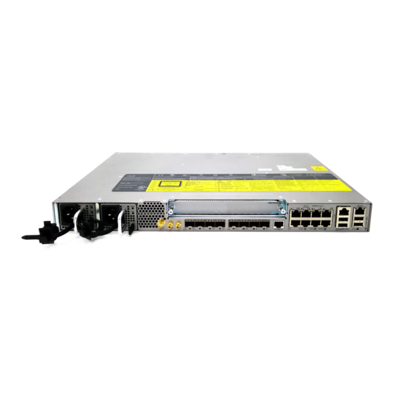
• Digital optical monitoring as specified by the optical transceiver module. • Any mix of SFPs is supported unless specifically noted. • Pause flow control as defined by the 802.3x standard. • Frame size of 9216 bytes. Cisco ASR-920-12SZ-IM Aggregation Services Router Hardware Installation Guide... - Page 16 SFP+ Ports The following figures show the port numbering for the Cisco ASR 920 router: Figure 1: Front Panel of Cisco ASR-920-12SZ-IM Router — With DC Power Supply Figure 2: Front Panel of Cisco ASR-920-12SZ-IM Router — With AC Power Supply...
-
Page 17: Cisco Asr-920-12Sz-Im Aggregation Services Router Hardware Installation Guide
SMB Snap-in connector USB Memory port (10MHZ) SMB Snap-in connector USB Console port (1PPS) Four 1G/10G SFP+ Zero Touch Provisioning button Interface Module RS232 Console port Four 1G SFP RS232 Aux Console port Cisco ASR-920-12SZ-IM Aggregation Services Router Hardware Installation Guide... -
Page 18: Cisco Asr-920-12Sz-Im Aggregation Services Router Hardware Installation Guide
Figure 3: Rear View of Cisco ASR-920-12SZ-IM Router Fan tray Air vents Grounding lug — The following table describes the other features of Cisco ASR-920-12SZ-IM (AC and DC) Router. Table 1: Cisco ASR-920-12SZ-IM Router Specifications Specification ASR-920-12SZ-IM DimensionWidth x Depth x Height 17.5 x 9.88 x 1.73 inches... -
Page 19: Cisco Asr-920-12Sz-Im Aggregation Services Router Hardware Installation Guide
Ports 12 to 15 are Dual Rate ports Copper/1G/10G Port LEDs Link/Activity/Fault Temperature Sensors Four temperature sensors 1PPS/ToD External ports for 1PPS/TOD Provides power over Ethernet GNSS Connects to the external GPS Cisco ASR-920-12SZ-IM Aggregation Services Router Hardware Installation Guide... -
Page 20: External Interfaces
PoE/PoE+/UPoE with overall power budget of 180 W. PoE is not supported when the system is powered with 24 V DC. Note • 10GE SFP+—supports 10G/1G mode depending on the SFP+/SFP in the network interface slot. Cisco ASR-920-12SZ-IM Aggregation Services Router Hardware Installation Guide... -
Page 21: Network Timing Interfaces
The RS232 console port provides transmission (Tx), reception (Rx), and ground (Gnd). Note The RS232 console port is enabled only through the Cisco-designed cable adapter USB type A cable to RJ-45 adapter cable. To use this port, disable the flow control on the terminal. -
Page 22: Usb Console
A single USB 2.0 Type-A receptacle on the front panel of the router provides console access to ROMMON, Cisco IOS-XE and diagnostics. While it uses the Type-A connector, it operates as a USB peripheral only for connection to an external host computer. This interface requires the use of a Type-A to Type-A connector instead of a standard USB cable. -
Page 23: Led Indicators
Table 3: PWR and STAT LED Indications PWR LED State STAT LED state Indication Comment Amber Power in the system is all Permanent Amber/Off right and FPGA indicates FPGA configuration is taking configuration failure. place. Cisco ASR-920-12SZ-IM Aggregation Services Router Hardware Installation Guide... -
Page 24: Cisco Asr-920-12Sz-Im Aggregation Services Router Hardware Installation Guide
Green Amber A minor alarm or — synchronization is in Holdover or free-running mode Green A major or critical alarm — (high temperature reported for any sensor) or multiple fan failure. Cisco ASR-920-12SZ-IM Aggregation Services Router Hardware Installation Guide... -
Page 25: Cpu Management Port Leds
Labeled same as the SFP port Green Link up in number 1000Base-X/100Base-FX Blinking Green Activity in 1000 Base-X/100Base-FX Amber Fault/Error/Link down Administratively down SFP+ LEDs Each SFP+ port has an LED indicator. Cisco ASR-920-12SZ-IM Aggregation Services Router Hardware Installation Guide... -
Page 26: Rj-45 Leds
FAIL LED Power Supply Condition Green Power Supply ON; valid input/output Yellow 1Hz blinking Red 1Hz blinking PSU Warning due to OCP, OTP, UV, OV, OP, abnormal fan operation PSU continues to operate Cisco ASR-920-12SZ-IM Aggregation Services Router Hardware Installation Guide... -
Page 27: System-Interface Led Behavior
Dual Rate (1G/10G) Port LEDs ROMMON IOS Shut IOS No shut (cable disconnect) Amber IOS No shut (Link Up) Green Table 11: Management Port LED Indication Event Management Port LEDs (Link/Duplex) ROMMON Green/Off IOS Shut Off/Off Cisco ASR-920-12SZ-IM Aggregation Services Router Hardware Installation Guide... -
Page 28: Online Insertion And Removal
• Feature licensing The following methods are used to activate the above licenses: • Cisco Software Licensing—The Cisco Software License Activation feature is a set of processes and components to activate Cisco software feature sets by obtaining and validating fee-based Cisco software licenses. - Page 29 Cisco ASR 920 Series Aggregation Services Router Overview Licensing Licenses generated by the Cisco Software Licensing are tied to the UDI of the chassis and a corresponding Note watchtower device certificate (WDC) is stored in the system. • Cisco Smart Licensing—Smart Licensing is usage-based licensing where devices register with the Cisco Secure server.
- Page 30 Cisco ASR 920 Series Aggregation Services Router Overview Licensing Cisco ASR-920-12SZ-IM Aggregation Services Router Hardware Installation Guide...
-
Page 31: Preparing For Installation
• Installation Checklist, page 31 • Creating a Site Log, page 32 • Chassis-Lifting Guidelines, page 33 • Tools and Equipment, page 33 • Unpacking and Verifying the Shipped Contents, page 34 Cisco ASR-920-12SZ-IM Aggregation Services Router Hardware Installation Guide... -
Page 32: Safety Guidelines
Statement 43 For other standard warning messages and their translations, see the Regulatory Compliance and Safety Information for the Cisco ASR 920 Series Aggregation Services Router document. Safety Guidelines for Personal Safety and Equipment Protection The following guidelines help ensure your safety and protect the equipment. -
Page 33: Safety Precautions For Module Installation And Removal
Information for the Cisco ASR 920 Series Aggregation Services Router document. Safety with Electricity To see the safety with electricity, see the Regulatory Compliance and Safety Information for the Cisco ASR 920 Series Aggregation Services Router document. When working on equipment powered by electricity, follow these guidelines: •... -
Page 34: Power Supply Considerations
• Never attempt to remove the printed circuit board from the metal carrier. Note For the safety of your equipment, periodically check the resistance value of the antistatic wrist strap. It should be between 1 and 10 Mohm. Cisco ASR-920-12SZ-IM Aggregation Services Router Hardware Installation Guide... -
Page 35: Site Planning
Preparing for Installation Site Planning Site Planning The sections describe how to plan for the installation of the Cisco ASR 920 Series Router. General Precautions Observe the following general precautions when using and working with your router:: • Keep your system components away from radiators and heat sources and do not block cooling vents. -
Page 36: Site Selection Guidelines
The routers are designed to meet the industry EMC, safety, and environmental standards described in the Regulatory Compliance and Safety Information for the Cisco ASR 920 Series Router document. Environmental Requirements Environmental monitoring of the Cisco ASR 920-24SZ-IM, ASR-920-24SZ-M, ASR-920-24TZ-M Router protects the system and components from damage caused by excessive voltage and temperature conditions. - Page 37 Air Flow Guidelines The direction of air flow is from front-to-back. Figure 5: Air Flow in the Cisco ASR 920 Series Routers To ensure adequate air flow through the equipment rack, it is recommended that you maintain a minimum clearance distance as mentioned below, at all times.
-
Page 38: Air Flow Guidelines For Etsi Rack Installation
Air Flow Guidelines for ETSI Rack Installation To install a Cisco ASR 920 Series Router in a 2-post or 4-post rack, the front and rear doors of the cabinet must be removed. It is recommended that you maintain a minimum clearance distance as mentioned below, at all times. -
Page 39: Site Power Guidelines
This section contains guidelines for wiring and cabling at your site. When preparing your site for network connections to the router, consider the type of cable required for each component, and the cable limitations. Cisco ASR-920-12SZ-IM Aggregation Services Router Hardware Installation Guide... -
Page 40: Asynchronous Terminal Connections
Strong EMI can destroy the signal drivers and receivers in the router and even create an electrical hazard by causing power surges through the power lines into installed equipment. These problems are rare, but could be catastrophic. Cisco ASR-920-12SZ-IM Aggregation Services Router Hardware Installation Guide... -
Page 41: Radio Frequency Interference
If you have previously experienced such problems, you should consult with RFI and EMI experts to ensure that you have adequate electrical surge suppression and shielding of signal cables in your Cisco ASR 920 Series Router operating environment. -
Page 42: Rack Selection Guidelines
Locating for Safety If the Cisco ASR 920 Series Router is the heaviest or the only piece of equipment in the rack, consider installing it at or near the bottom to ensure that the rack’s center of gravity is as low as possible. -
Page 43: Locating For Proper Airflow
To assist you with your installation and to provide a record of what was done by whom and when, photocopy the Cisco ASR 920 Series Router Installation Checklist shown in the table below. Use this to record the completion and verification of each procedure. After the checklist is completed, place it in your Site Log along with the other records pertaining to your new Cisco router. -
Page 44: Creating A Site Log
The Site Log provides a record of all the actions related to installing and maintaining the router. Keep it in an accessible place near the chassis so that anyone who performs tasks has access to it. Cisco ASR-920-12SZ-IM Aggregation Services Router Hardware Installation Guide... -
Page 45: Chassis-Lifting Guidelines
• Console terminal (an ASCII terminal or a PC running terminal emulation software) that is configured for 9600 baud, 8 data bits, no parity, no flow control, and 1stop bit • Console cable for connecting to the console port Cisco ASR-920-12SZ-IM Aggregation Services Router Hardware Installation Guide... -
Page 46: Unpacking And Verifying The Shipped Contents
Use the table below to check the contents of the Cisco ASR 920-24SZ-IM, ASR-920-24SZ-M, ASR-920-24TZ-M Router shipping container. Do not discard the shipping container. You will need the container if you move or ship the Cisco ASR 920-24SZ-IM, ASR-920-24SZ-M, ASR-920-24TZ-M Router in the future. - Page 47 Note Most Cisco documentation is available online. The Cisco ASR 920 Series Aggregation Services Router Pointer Card that is shipped with your Cisco ASR 920 Series Router contains links and information about the various documents that are available online. Cisco ASR-920-12SZ-IM Aggregation Services Router Hardware Installation Guide...
- Page 48 Preparing for Installation Unpacking and Verifying the Shipped Contents Cisco ASR-920-12SZ-IM Aggregation Services Router Hardware Installation Guide...
-
Page 49: Installing The Cisco Asr 920 Series Router
Connecting to the Copper Ports, page 55 • Installing the Chassis Ground Connection, page 57 • Installing and Removing the Fan Tray, page 60 • Interface Module Installation, page 63 • Installing the Power Supply, page 65 Cisco ASR-920-12SZ-IM Aggregation Services Router Hardware Installation Guide... -
Page 50: Prerequisites
For more instructions on how to prepare for the installation of the router, see Preparing for Installation section. Installing the Router in a Rack Each Cisco ASR 920 Series Aggregation Services Router router includes rack-mounting brackets. Using the rack-mounting brackets, you can mount the router in a 19-inch, 23-inch, or an ETSI rack that conforms to the EIA-310-D specification. -
Page 51: Attaching Brackets To The Router
The bracket mounting screws are pre-installed on the router. Depending on the bracket mounting position of the chassis, you must remove the appropriate screws, fix the bracket, and install the screws again. Cisco ASR-920-12SZ-IM Aggregation Services Router Hardware Installation Guide... -
Page 52: Attaching Brackets For 19-Inch Racks
Installing the Cisco ASR 920 Series Router Attaching Brackets to the Router Attaching Brackets for 19-Inch Racks The following figure shows how to attach brackets for 19-inch racks on the router. Figure 7: Attaching Brackets for 19-Inch Racks Cisco ASR-920-12SZ-IM Aggregation Services Router Hardware Installation Guide... - Page 53 Installing the Cisco ASR 920 Series Router Attaching Brackets to the Router Phillips flat-head screws Front-mounting position Mid-mounting position Rear-mounting position Cisco ASR-920-12SZ-IM Aggregation Services Router Hardware Installation Guide...
-
Page 54: Attaching Brackets For 23-Inch Racks
Installing the Cisco ASR 920 Series Router Attaching Brackets to the Router Attaching Brackets for 23-Inch Racks The following figure shows how to attach brackets for 23-inch racks on the router. Figure 8: Attaching Brackets for 23-Inch Racks Cisco ASR-920-12SZ-IM Aggregation Services Router Hardware Installation Guide... - Page 55 Installing the Cisco ASR 920 Series Router Attaching Brackets to the Router Phillips flat-head screws Front-mounting position Mid-mounting position Rear-mounting position Cisco ASR-920-12SZ-IM Aggregation Services Router Hardware Installation Guide...
-
Page 56: Attaching Brackets For Etsi Racks
Installing the Cisco ASR 920 Series Router Attaching Brackets to the Router Attaching Brackets for ETSI Racks The following figure shows how to attach brackets for ETSI racks on the router. Figure 9: Attaching Brackets for ETSI Racks Cisco ASR-920-12SZ-IM Aggregation Services Router Hardware Installation Guide... -
Page 57: Mounting The Router In A Rack
#6-32 x 0.25-inch mounting screws (two on each side). 9. Tighten the screws using a 1/4-inch flat-blade screwdriver (each side). The recommended maximum torque is 10 in.-lb. Cisco ASR-920-12SZ-IM Aggregation Services Router Hardware Installation Guide... -
Page 58: Installing The Router Chassis In The Rack
4. Use a tape measure and level to verify that the chassis is installed straight and level. DETAILED STEPS Step 1 Position the chassis in the rack as follows: Cisco ASR-920-12SZ-IM Aggregation Services Router Hardware Installation Guide... -
Page 59: Attaching The Cable Guides
Use a tape measure and level to verify that the chassis is installed straight and level. Attaching the Cable Guides The Cisco ASR 920 Series Router supports the following cable guides: • A920-CBL-GUIDE (left and right)—help in routing the cables from all components on the front panel thereby enabling a proper cable-bending radius. - Page 60 Position the cable guide-left and cable guide-right against the front of the chassis and align the four screw holes, as shown in the following figure. Figure 11: Cable Guide Installation For 19-inch Rack Brackets Figure 12: Cable Guide Installation For ETSI Rack Brackets Cisco ASR-920-12SZ-IM Aggregation Services Router Hardware Installation Guide...
-
Page 61: Wall Mounting The Router
To install the router on a wall, follow the instructions in these procedures: Attaching the Brackets to the Router for Wall-Mounting While wall mounting the router, always ensure that the power supplies are at the top position. Note Cisco ASR-920-12SZ-IM Aggregation Services Router Hardware Installation Guide... -
Page 62: Mounting Router On The Wall
For the best support of the router and cables, ensure the router is attached securely to wall studs or to a firmly attached plywood mounting backboard. Suitable for mounting on and over a concrete or other non-combustible surface only. Statement 345 Warning Cisco ASR-920-12SZ-IM Aggregation Services Router Hardware Installation Guide... - Page 63 Mount the router with the front panel as shown in the following figure. Figure 15: Mounting the Router on the Wall Caution When mounting the router vertically, ensure that the power supplies are at the top. Cisco ASR-920-12SZ-IM Aggregation Services Router Hardware Installation Guide...
-
Page 64: Installing And Removing Sfp Modules
Use only Cisco SFP modules on the Cisco router. Each SFP module has an internal serial EEPROM that is encoded with security information. This encoding provides a way for Cisco to identify and validate that the SFP module meets the requirements for the router. - Page 65 Insert the cable connector into the SFP module: • For fiber-optic SFP modules, insert the LC cable into the SFP module. • For copper 1000BASE-T SFP modules, insert the RJ-45 cable connector into the SFP module. Cisco ASR-920-12SZ-IM Aggregation Services Router Hardware Installation Guide...
-
Page 66: Removing Sfp Modules
Disconnect the cable from the SFP module, and insert a dust plug into the cable end. For reattachment, note which cable connector plug is send (TX) and which is receive (RX). Step 3 Unlock and remove the SFP module, as shown in the following figure. Cisco ASR-920-12SZ-IM Aggregation Services Router Hardware Installation Guide... -
Page 67: Connecting To The Copper Ports
Connecting devices that do not autonegotiate or that have their speed and duplex parameters manually set can reduce performance or result in no linkage. Cisco ASR-920-12SZ-IM Aggregation Services Router Hardware Installation Guide... -
Page 68: Connecting To Sfp Modules
For instructions about how to install or remove an SFP module, see the Installing and Removing SFP Modules section. Connecting to Fiber-Optic SFP Modules Follow these steps to connect a fiber-optic cable to an SFP module: Cisco ASR-920-12SZ-IM Aggregation Services Router Hardware Installation Guide... -
Page 69: Installing The Chassis Ground Connection
Before you connect the power or turn on the power to the router, you must provide an adequate chassis ground (earth) connection to your router. This section describes how to ground the chassis. The grounding lug location is on the back panel of the router. Cisco ASR-920-12SZ-IM Aggregation Services Router Hardware Installation Guide... - Page 70 Statement 1024 Use copper conductors only. Statement 1025 Warning When installing the unit, the ground connection must always be made first and disconnected last. Statement Warning Cisco ASR-920-12SZ-IM Aggregation Services Router Hardware Installation Guide...
- Page 71 Step 1 If your ground wire is insulated, use a wire-stripping tool to strip the ground wire to 0.5 inch ± 0.02 inch (12.7 mm ±0.5 mm). Figure 20: Stripping a Ground Wire Cisco ASR-920-12SZ-IM Aggregation Services Router Hardware Installation Guide...
-
Page 72: Installing And Removing The Fan Tray
Electric Shock Hazard: This fan tray has to be serviced by trained personnel only. Always wear the ESD wrist strap when installing or uninstalling the fan tray. Caution Unplug all power sources before performing this procedure. Caution Cisco ASR-920-12SZ-IM Aggregation Services Router Hardware Installation Guide... - Page 73 Push the fan assembly into the chassis until the power connector seats in the backplane and the captive installation screws make contact with the chassis. Step 3 Tighten the captive installation screws, using a flat-blade or number 2 Phillips-head screwdriver. Cisco ASR-920-12SZ-IM Aggregation Services Router Hardware Installation Guide...
-
Page 74: Removing The Fan Tray
3. Grasp the fan assembly with both hands, and pull it outward; rock it gently, if necessary, to unseat the fan assembly power connector from the backplane. 4. Pull the fan assembly clear of the chassis, and set it aside. Cisco ASR-920-12SZ-IM Aggregation Services Router Hardware Installation Guide... -
Page 75: Interface Module Installation
Step 4 Pull the fan assembly clear of the chassis, and set it aside. Interface Module Installation The following sections describe the various tasks of associated with interface module installation: Cisco ASR-920-12SZ-IM Aggregation Services Router Hardware Installation Guide... -
Page 76: Installing An Interface Module
Slide the interface module out of the router slot by pulling on the handles. If you are removing a blank filler plate, pull the blank filler plate completely out of the router slot using the captive screws. Cisco ASR-920-12SZ-IM Aggregation Services Router Hardware Installation Guide... -
Page 77: Installing The Power Supply
Installing the Power Supply Installing the Power Supply The Cisco ASR 920 Router router provides the choice of two different power supplies: • DC power—The DC power supply uses 2-position terminal block-style connector with positive latching/securing and labeled connections for +24/48V, GRD, -24/48V. The terminal block connector is of suitable size to carry the appropriate AWG wire size to handle the input current of the power supply. -
Page 78: Guidelines For Dc-Powered Systems
• In some systems, you can use an UPS to protect against power failures at your site. Avoid UPS types that use ferroresonant technology. These UPS types can become unstable with systems such as the Cisco ASR 920 Series Router, which can have substantial current-draw fluctuations due to bursty data traffic patterns. -
Page 79: Installing The Dc Power Supply Module
Installing the Cisco ASR 920 Series Router Installing the DC Power Supply Module Use the information in the Cisco ASR-920-12SZ-IM Router Specifications table to estimate the power requirements and heat dissipation of the router based on a given configuration of the router. Determining power requirements is useful for planning the power distribution system needed to support the router. - Page 80 Make sure that the power supply is fully seated in the bay. Step 5 Tighten the captive installation screws of the power supply. The recommended maximum torque is 5.5 in.-lb (0.62 N-m). Figure 24: Installing the DC Power Supply Module Cisco ASR-920-12SZ-IM Aggregation Services Router Hardware Installation Guide...
-
Page 81: Activating A Dc Power Supply Module
Installing the DC Power Cables Note When installing DC power supply, use 14 AWG, 90°C wires. Always ensure that the building’s installation for short-circuit (overcurrent) protection does not exceed 15A. Cisco ASR-920-12SZ-IM Aggregation Services Router Hardware Installation Guide... - Page 82 2. Insert the DC-input power source wires into the terminal block plug. 3. Attach the DC supply wires using the designated screws. 4. Use a ratcheting torque screwdriver to torque the terminal block plug captive screw. See the following figure. Cisco ASR-920-12SZ-IM Aggregation Services Router Hardware Installation Guide...
-
Page 83: Removing The Dc Power Supply Module
Removing the DC Power Supply Module This section provides information about removing and replacing the DC power supply. Before performing any of the following procedures, ensure that power is removed from the DC circuit. Warning Statement 1003 Cisco ASR-920-12SZ-IM Aggregation Services Router Hardware Installation Guide... - Page 84 5. Loosen the captive screws on the DC power supply. 6. Grasp the power supply handle. Simultaneously press the power supply lock towards the left and pull the power supply out from the chassis while supporting it with the other hand. Cisco ASR-920-12SZ-IM Aggregation Services Router Hardware Installation Guide...
-
Page 85: Installing The Ac Power Supply Module
Figure 27: Removing the DC Power Supply Module Installing the AC Power Supply Module Follow these steps to install the AC power supply module: Cisco ASR-920-12SZ-IM Aggregation Services Router Hardware Installation Guide... - Page 86 4. Slide the AC power supply cord inside the tie of the tie-and-holder and tighten the tie around the power supply cord. 5. Plug the power supply cord into the AC power supply. Cisco ASR-920-12SZ-IM Aggregation Services Router Hardware Installation Guide...
- Page 87 Slide the AC power supply cord inside the tie of the tie-and-holder and tighten the tie around the power supply cord. Step 5 Plug the power supply cord into the AC power supply. Cisco ASR-920-12SZ-IM Aggregation Services Router Hardware Installation Guide...
-
Page 88: Installing The Ac Power Cables
Insert the power supply cord into the tie [1] and tighten the tie around the power supply cord as shown in [2] in the figure below. Figure 29: Attaching the AC Power Tie-and-Clip Cord Cisco ASR-920-12SZ-IM Aggregation Services Router Hardware Installation Guide... -
Page 89: Activating An Ac Power Supply Module
Only trained and qualified personnel should be allowed to install, replace, or service this equipment. Warning Statement 1030 Installation of the equipment must comply with local and national electrical codes. Statement 1074 Warning Follow these steps to remove and replace the AC power supply: Cisco ASR-920-12SZ-IM Aggregation Services Router Hardware Installation Guide... - Page 90 4. Grasp the power supply handle. Simultaneously press the power supply lock towards the left and pull the power supply out from the chassis while supporting it with the other hand. Cisco ASR-920-12SZ-IM Aggregation Services Router Hardware Installation Guide...
- Page 91 Grasp the power supply handle. Simultaneously press the power supply lock towards the left and pull the power supply out from the chassis while supporting it with the other hand. Figure 30: Removing the AC Power Supply Module Cisco ASR-920-12SZ-IM Aggregation Services Router Hardware Installation Guide...
-
Page 92: Powering On The Router
Install the USB device driver before establishing a physical connection between the router and the PC, by using the USB console cable plugged into the USB serial port. Otherwise, the connection will fail. For more information, see the Installing the Cisco USB Device Driver section. SUMMARY STEPS 1. -
Page 93: Connecting To The Console Port Using Mac Os X
Connect to the USB port with the following command followed by the router USB port speed: Example: macbook:user$ screen /dev/tty.usbmodem1a21 9600 To disconnect the OS X USB console from the terminal window, enter Ctrl-a followed by Ctrl-\ Cisco ASR-920-12SZ-IM Aggregation Services Router Hardware Installation Guide... -
Page 94: Connecting To The Console Port Using Linux
Tools and Resources Download Software site, USB Console Software category, at: https://software.cisco.com/download/ release.html?mdfid=286037604&flowid=71056&softwareid=282855122&release=3.13&relind=A V AILABLE&rellifecycle=&reltype=latest Note To download the driver, you must have a valid service contract associated to your Cisco.com profile. Cisco ASR-920-12SZ-IM Aggregation Services Router Hardware Installation Guide... - Page 95 Connect the USB cable to the PC and router USB console ports. Follow the on-screen instructions to complete the installation of the driver. Step 6 XR21V1401 USB UART Device driver successfully installed message is displayed. The USB console is ready for use. Cisco ASR-920-12SZ-IM Aggregation Services Router Hardware Installation Guide...
-
Page 96: Uninstalling The Cisco Usb Driver
Installing the Cisco ASR 920 Series Router Connecting Console Cables Uninstalling the Cisco USB Driver Figure 31: Connecting the USB Console Cable to the Cisco ASR 920 Series Router USB Type-A console port USB Type-A to USB Type-A console cable This procedure describes how to uninstall the Microsoft Windows USB device driver in Microsoft Windows XP, Windows Vista, Windows 2000, Windows 7, and Windows 8. -
Page 97: Connecting To The Eia Console Port
3. Connect the DB-9 end of the console cable to the DB-9 end of the terminal. 4. To communicate with the router, start a terminal emulator application, such as Microsoft Windows HyperTerminal. This software should be configured with the following parameters: Cisco ASR-920-12SZ-IM Aggregation Services Router Hardware Installation Guide... - Page 98 Connect the USB end of the USB-to RJ-45 cable to the EIA Console port. Step 2 Connect the RJ-45 end of the DB-9 adapter cable to the USB-to RJ-45 cable, as shown in the following figure. Figure 32: Connecting a Modem to the Cisco ASR 920 Series Router Label Component...
-
Page 99: Connecting A Management Ethernet Cable
Installing and Removing SFP and SFP+ Modules The Cisco ASR 920 Series Router supports a variety of SFP and SFP+ modules, including optical and Ethernet modules. For information on how to install and remove SFP and SFP+ modules, see the documentation for the SFP or SFP+ module at: http://www.cisco.com/en/US/partner/products/hw/modules/ps5455/prod_installation_guides_list.html... -
Page 100: Removing A Usb Flash Device
Step 2 To replace the Cisco USB Flash memory stick, simply insert the module into the USB port labeled USB MEM. The Flash memory module can be inserted only one way, and can be inserted or removed regardless of whether the router is powered up or not. -
Page 101: Connecting A Cable To The Input 10-Mhz Or 1-Pps Interface
Connect one end of a shielded mini-coax cable to the GPS unit. Step 2 Connect the other end of the shielded mini-coax cable to the 10-Mhz or 1-PPS port on the Cisco ASR 920 Series Router. Connecting a Cable to the Output 10-Mhz or 1-PPS Interface SUMMARY STEPS 1. -
Page 102: Connecting A Cable To The Gnss Antenna Interface
Connect one end of a straight-through Ethernet cable to the GPS unit. Step 2 Connect the other end of the straight-through Ethernet cable to the ToD or 1-PPS port on the Cisco ASR 920 Series Router. What to Do Next... -
Page 103: Connecting Ethernet Cables
Connecting Ethernet Cables Connecting Ethernet Cables The Cisco ASR 920 Series Router interface modules support RJ-45 and Ethernet SFP ports. For instructions on how to connect cables to Ethernet SFP ports, see the Connecting Cables to SFP Modules section. The RJ-45 port supports standard straight-through and crossover Category 5 unshielded twisted-pair (UTP) cables. - Page 104 Installing the Cisco ASR 920 Series Router Connector and Cable Specifications Cisco ASR-920-12SZ-IM Aggregation Services Router Hardware Installation Guide...
-
Page 105: Initial Configuration
Cisco IOS software configuration documentation set that corresponds to the software release installed on your Cisco hardware. To configure a Cisco ASR 920 Series Aggregation Services Router from a console, connect a terminal to the router console port. -
Page 106: Powering Up The Router
• show diag slot—Displays the IDPROM information for the assemblies in the chassis. Checking Hardware and Software Compatibility To check the minimum software requirements of Cisco IOS-XE software with the hardware installed on your router, Cisco maintains the Software Advisor tool on Cisco.com. The tool provides the minimum Cisco IOS requirements for individual hardware modules and components. -
Page 107: Configuring The Router At Startup
IOS Master Command List, All Releases guides. To configure a Cisco ASR 920 Series Router from the console, you must connect a terminal or terminal server to the console port on the Cisco ASR 920 Series Router. To configure the router using the management Ethernet port, you must have the router’s IP address. -
Page 108: Configuring Global Parameters
2. The first sections of the configuration script appear only at an initial system startup. On subsequent uses of the setup facility, the script begins with a System Configuration Dialog as shown below: When you are prompted about whether you want to enter the initial configuration dialog, enter yes. Cisco ASR-920-12SZ-IM Aggregation Services Router Hardware Installation Guide... -
Page 109: Checking The Running Configuration Settings
This ensures that the operating system cleans up all the file systems. After the reload operation is complete, the router can be powered off safely. To power off the router safely,: Cisco ASR-920-12SZ-IM Aggregation Services Router Hardware Installation Guide... - Page 110 3. Confirm the reload command. 4. After confirming the reload command, wait until the system bootstrap message is displayed before powering off the system: 5. Remove power cables, if any, from the Cisco ASR 920-24SZ-IM, ASR-920-24SZ-M, ASR-920-24TZ-M Router: DETAILED STEPS Step 1 Slip on the ESD-preventive wrist strap included in the accessory kit.
-
Page 111: Troubleshooting
C H A P T E R Troubleshooting This chapter provides information about troubleshooting issues, if any, on the Cisco ASR 920 Series Aggregation Services Router. • Pinouts, page 99 • LED Summary, page 103 Pinouts The sections describe the pinouts for the Cisco ASR 920 Series Router interfaces: GPS Port Pinouts The table below summarizes the GPS port pinouts. -
Page 112: Time-Of-Day Port Pinouts
Table 16: External Alarm Input Pinouts Signal Name Description ALARM0_IN Alarm input 0 ALARM1_IN Alarm input 1 — No connect ALARM2_IN Alarm input 2 ALARM3_IN Alarm input 3 — No connect — No connect Cisco ASR-920-12SZ-IM Aggregation Services Router Hardware Installation Guide... -
Page 113: Management Gigabitethernet Port Pinouts
TRP1- TRP3+ TRP3- USB Console Port Pinouts The table below summarizes the USB console port pinouts. Table 18: Single USB Console Port Pinouts Signal Name Description +5VDC Data - Data + Ground Cisco ASR-920-12SZ-IM Aggregation Services Router Hardware Installation Guide... -
Page 114: Usb Flash Or Mem Port Pinouts
Within the multimode category, only short reach is available. For information about optical SFP modules, see the documentation for the SFP module at: http://www.cisco.com/en/US/partner/products/hw/modules/ ps5455/prod_installation_guides_list.html Alarm Conditions The table below summarizes the meaning of the alarm conditions on the Cisco ASR 920 Series Router. Cisco ASR-920-12SZ-IM Aggregation Services Router Hardware Installation Guide... -
Page 115: Led Summary
PSU failure due to OCP, OTP, UV, OV, OP, abnormal fan operation. No valid output. Green 1Hz blinking Valid power present, shutdown by system. Yellow Input voltage low No valid power input. Cisco ASR-920-12SZ-IM Aggregation Services Router Hardware Installation Guide... -
Page 116: Fan Tray Leds
The table below summarizes the Fan Tray LEDs. Table 22: Fan Tray LEDs Color/State Description System is not powered on Green All the fans are working normally Single or multiple fan failures and critical error Cisco ASR-920-12SZ-IM Aggregation Services Router Hardware Installation Guide... -
Page 117: Site Log
• Upgrade, removal, and maintenance procedures—Use the Site Log as a record of ongoing router maintenance and expansion history. Each time a task is performed on the Cisco ASR 920 Series Router, update the Site Log to reflect the following: ◦... - Page 118 Site Log Date Description of Action Performed or Initials Symptom Observed Cisco ASR-920-12SZ-IM Aggregation Services Router Hardware Installation Guide...
Need help?
Do you have a question about the ASR-920-12SZ-IM and is the answer not in the manual?
Questions and answers