Cisco ASR-920-24SZ-IM Installation Manual
Router
Hide thumbs
Also See for ASR-920-24SZ-IM:
- Hardware installation manual (150 pages) ,
- Configuration manual (13 pages)
Table of Contents
Advertisement
Cisco ASR-920-24SZ-IM, ASR-920-24SZ-M,
ASR-920-24TZ-M Aggregation Services
Router Hardware Installation Guide
December 10, 2014
Cisco Systems, Inc.
www.cisco.com
Cisco has more than 200 offices worldwide.
Addresses, phone numbers, and fax numbers
are listed on the Cisco website at
www.cisco.com/go/offices.
Text Part Number: NA
Advertisement
Table of Contents

Related Manuals for Cisco ASR-920-24SZ-IM


Summary of Contents for Cisco ASR-920-24SZ-IM
- Page 1 Cisco ASR-920-24SZ-IM, ASR-920-24SZ-M, ASR-920-24TZ-M Aggregation Services Router Hardware Installation Guide December 10, 2014 Cisco Systems, Inc. www.cisco.com Cisco has more than 200 offices worldwide. Addresses, phone numbers, and fax numbers are listed on the Cisco website at www.cisco.com/go/offices. Text Part Number: NA...
- Page 2 CONNECTION WITH USER’S USE OF THE SOFTWARE. Cisco and the Cisco logo are trademarks or registered trademarks of Cisco and/or its affiliates in the U.S. and other countries. To view a list of Cisco trademarks, go to this URL: www.cisco.com/go/trademarks. Third-party trademarks mentioned are the property of their respective owners. The use of the word partner does not imply a partnership relationship between Cisco and any other company.
-
Page 3: Table Of Contents
SFP+ LEDs 1-15 8 T1/E1 Interface Module LEDs 1-15 RJ-45 LEDs 1-16 Power Supply Unit LEDs 1-16 System–Interface LED Behavior 1-17 Online Insertion and Removal 1-17 Licensing the Router 1-18 Cisco ASR-920-24SZ-IM, ASR-920-24SZ-M, ASR-920-24TZ-M Aggregation Services Router Hardware Installation Guide... - Page 4 C H A P T E R Prerequisites Installing the Router in a Rack Installing the Chassis Brackets Installing the Router Chassis in the Rack 3-11 Attaching the Cable Guides 3-13 Cisco ASR-920-24SZ-IM, ASR-920-24SZ-M, ASR-920-24TZ-M Aggregation Services Router Hardware Installation Guide...
- Page 5 Guidelines for AC-Powered Systems 3-47 Preventing Power Loss 3-47 Activating a DC Power Supply 3-48 Activating an AC Power Supply 3-48 Connecting a Router to the Network 3-48 Connecting Console Cables 3-49 Cisco ASR-920-24SZ-IM, ASR-920-24SZ-M, ASR-920-24TZ-M Aggregation Services Router Hardware Installation Guide...
- Page 6 4-11 Troubleshooting C H A P T E R Pinouts BITS Port Pinouts GPS Port Pinout Time-of-Day Port Pinouts Alarm Port Pinouts Management Ethernet Port Pinouts USB Console Port Pinouts Cisco ASR-920-24SZ-IM, ASR-920-24SZ-M, ASR-920-24TZ-M Aggregation Services Router Hardware Installation Guide...
- Page 7 USB Flash or MEM Port Pinouts RJ45C Port Pinouts Optical Fiber Specifications Alarm Conditions Site Log C H A P T E R Supported PIDs C H A P T E R Cisco ASR-920-24SZ-IM, ASR-920-24SZ-M, ASR-920-24TZ-M Aggregation Services Router Hardware Installation Guide...
- Page 8 Contents Cisco ASR-920-24SZ-IM, ASR-920-24SZ-M, ASR-920-24TZ-M Aggregation Services Router Hardware Installation Guide...
-
Page 9: Document Revision History
Cisco ASR 920 Series Aggregation Services Routers. It also lists sources for obtaining additional information and technical assistance from Cisco. This document covers the following variants of the Cisco ASR 920 Series Aggregation Services Routers: ASR-920-24SZ-IM— Twenty Four 1GE Fiber ports, Four 10G ports, and One slot for modular •... - Page 10 An exclamation point (!) or a pound sign (#) at the beginning of a line of code indicates a comment line. Means reader take note. Notes contain helpful suggestions or references to material not covered in the Note manual. Cisco ASR-920-24SZ-IM, ASR-920-24SZ-M, ASR-920-24TZ-M Aggregation Services Router Hardware Installation Guide...
-
Page 11: Obtaining Documentation And Submitting A Service Request
Subscribe to What’s New in Cisco Product Documentation, which lists all new and revised Cisco technical documentation as an RSS feed and delivers content directly to your desktop using a reader application. The RSS feeds are a free service. - Page 12 Cisco ASR-920-24SZ-IM, ASR-920-24SZ-M, ASR-920-24TZ-M Aggregation Services Router Hardware Installation Guide...
-
Page 13: Cisco Asr 920 Series Routers Features
C H A P T E R Overview The Cisco ASR 920 Series Aggregation Services Router is a family of modular and fixed configuration routers that enables Service Providers to provide business, residential, and mobile access services to their users. It is the Carrier Ethernet access platform providing Ethernet services. -
Page 14: Interface Modules
Frame size of 9216 bytes. • Interface Modules The Cisco ASR-920-24SZ-IM Router interface modules are field-replaceable units. In addition to the ports provided on an RSP, the Cisco ASR-920-24SZ-IM Router supports the following interface modules: Gigabit Ethernet RJ45 Interface Module (A900-IMA8T) •... -
Page 15: Gigabit Ethernet Rj45 Interface Module (A900-Ima8T)
“Installing the • Interface Module” section on page 3-19. To determine interfaces available on the RJ45 Gigabit Ethernet module, see the “Interface • Availability on Interface Modules” section on page 1-6. Cisco ASR-920-24SZ-IM, ASR-920-24SZ-M, ASR-920-24TZ-M Aggregation Services Router Hardware Installation Guide... -
Page 16: Gigabit Ethernet Xfp Interface Module (A900-Ima1X)
To determine interfaces available on the 10-Gigabit Ethernet XFP module, see the “Interface • Availability on Interface Modules” section on page 1-6. For information on supported SFPs, see the Cisco ASR 900 Series Aggregation Services Router • Interface Modules Data Sheet at http://www.cisco.com/c/en/us/products/routers/asr-903-series-aggregation-services-routers/datash eet-listing.html. -
Page 17: Port T1/E1 Interface Module (A900-Ima8D)
To determine interfaces available on the 2X10 GE SFP Gigabit Ethernet module, see the “Interface • Availability on Interface Modules” section on page 1-6. For information on supported SFPs, see the Cisco ASR 900 Series Aggregation Services Router • Interface Modules Data Sheet at http://www.cisco.com/c/en/us/products/routers/asr-903-series-aggregation-services-routers/datash eet-listing.html. -
Page 18: Interface Availability On Interface Modules
5-5. Interface Availability on Interface Modules Cisco ASR-920-24SZ-IM Router does not support over-subscription mode. You must disable the ports Note as appropriate to restrict the system usage to 64 Gbps. Enabling all the interfaces in over-subscription mode can result in an unpredictable system performance. -
Page 19: Front And Back Panel
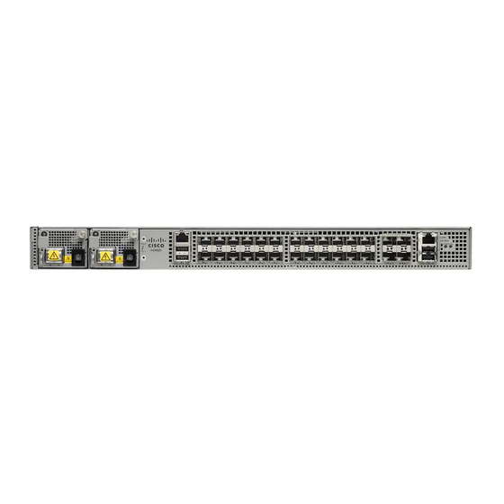
Chapter 1 Overview Cisco ASR 920 Series Routers Features Front and Back Panel The following figures show the port numbering for the Cisco ASR-920-24SZ-IM Router: Figure 1-5 Front Panel of Cisco ASR-920-24SZ-IM Router 17 18 14 15 Power Supply 0 (AC or DC) - Page 20 Console port (TIA/EIA-232F) USB Console port Management port Board power LED Auxiliary Console port System Status LED Figure 1-8 Back Panel of Cisco ASR-920-24SZ-M, ASR-920-24TZ-M Router Grounding lugs Fan status LED Cisco ASR-920-24SZ-IM, ASR-920-24SZ-M, ASR-920-24TZ-M Aggregation Services Router Hardware Installation Guide...
-
Page 21: Specifications
Overview Cisco ASR 920 Series Routers Features Specifications Table 1-3 describes the other features of Cisco ASR-920-24SZ-IM Router (AC and DC) and Cisco ASR-920-24SZ-M, ASR-920-24TZ-M Router (AC and DC) Routers. Table 1-3 Cisco ASR 920-24SZ-IM, ASR-920-24SZ-M, ASR-920-24TZ-M Router Specifications Specification... -
Page 22: External Interfaces
Network Interfaces The network interfaces are provided through fixed ports. GE SFP ports (fiber)—supports 100/1000 modes (ASR 920-24SZ-IM and ASR-920-24SZ-M) • GE SFP ports (copper)—supports 10/100/1000 operation (ASR-920-24TZ-M) • Cisco ASR-920-24SZ-IM, ASR-920-24SZ-M, ASR-920-24TZ-M Aggregation Services Router Hardware Installation Guide 1-10... -
Page 23: Network Timing Interfaces
GPS 1 PPS input and output—1 PPS input for GPS Synchronization. This connector on the front • panel can provide 1 PPS output as well from Cisco ASR-920-24SZ-IM Router. The direction can be configured using software. External Alarm Inputs The Cisco ASR 920-24SZ-IM, ASR-920-24SZ-M, ASR-920-24TZ-M Router supports four dry contact alarm inputs through an RJ-45 jack on the front panel. -
Page 24: Power Supply And Fans
RJ-45 adapter cable. To use this port, disable the flow control on the terminal. USB Console A single USB 2.0 Type-A receptacle is provided on the front panel of the Cisco ASR 920-24SZ-IM, ASR-920-24SZ-M, ASR-920-24TZ-M Router for providing console access to ROMMON, Cisco IOS-XE and diagnostics. -
Page 25: Led Indicators
For DC systems, if a surge of more than 1KV is expected, add an appropriate external surge protective device. The Cisco ASR 920-24SZ-IM, ASR-920-24SZ-M, ASR-920-24TZ-M Router have removable fan tray as part of the system. The fan tray is hot-swappable. The system is designed to operate at its maximum operating temperature of 70º... -
Page 26: Cpu Management Port Leds
Activity in 1000 Mbps Amber/Orange Link up in 100/10 Mbps Blinking Amber/Orange Activity in 100/10 Mbps Link down Right Green Link up in full duplex Link up in half duplex Cisco ASR-920-24SZ-IM, ASR-920-24SZ-M, ASR-920-24TZ-M Aggregation Services Router Hardware Installation Guide 1-14... -
Page 27: Sfp Leds
One or more configured ports are down Blinking amber One or more configured ports are down and at least one configured port is in a loopback state All ports disabled or shut down Cisco ASR-920-24SZ-IM, ASR-920-24SZ-M, ASR-920-24TZ-M Aggregation Services Router Hardware Installation Guide 1-15... -
Page 28: Rj-45 Leds
PSU LED Indication LED State Indication Green Power Supply is working and 12V output is alright. 12V output failure (Either input not present or fault in the power supply unit). Cisco ASR-920-24SZ-IM, ASR-920-24SZ-M, ASR-920-24TZ-M Aggregation Services Router Hardware Installation Guide 1-16... -
Page 29: Online Insertion And Removal
PSU could support the whole load. When a power supply is not working or the input cable is removed, the remaining power supply takes the entire load without disruption. Except for TDM IM, you can hot-swap an interface module with a similar interface module on Cisco •... -
Page 30: Licensing The Router
Cisco software feature sets by obtaining and validating fee-based Cisco software licenses. Licenses generated by the Cisco Software Licensing are tied to the UDI of the chassis and a Note corresponding watchtower device certificate (WDC) is stored in the system. -
Page 31: Preparing For Installation
C H A P T E R Preparing for Installation This chapter describe how to prepare for the installation of the Cisco ASR 920-24SZ-IM, ASR-920-24SZ-M, ASR-920-24TZ-M Router at your site, and contains the following sections: Safety Guidelines, page 2-1 •... -
Page 32: Safety Guidelines
Statement 340 This equipment is in compliance with the essential requirements and other relevant provisions of Warning Directive 1999/5/EC. Statement 287 Cisco ASR-920-24SZ-IM, ASR-920-24SZ-M, ASR-920-24TZ-M Aggregation Services Router Hardware Installation Guide... -
Page 33: Safety Guidelines For Personal Safety And Equipment Protection
Be sure to observe the following safety precautions when you work on the router. To see the translations of the warnings that appear in this publication, see the Regulatory Compliance and Safety Information for the Cisco ASR 920 Series Router document. Class 1 laser product. Statement 1008 Warning Do not stare into the beam or view it directly with optical instruments. - Page 34 Statement 1024 Warning Use copper conductors only. Statement 1025 This unit might have more than one power supply connection. All connections must be removed to Warning de-energize the unit. Statement 1028 Cisco ASR-920-24SZ-IM, ASR-920-24SZ-M, ASR-920-24TZ-M Aggregation Services Router Hardware Installation Guide...
- Page 35 Never perform any action that creates a potential hazard to people or makes the equipment unsafe. • If an electrical accident occurs, proceed as follows: • Use caution, and do not become a victim yourself. – Turn off power to the router. – Cisco ASR-920-24SZ-IM, ASR-920-24SZ-M, ASR-920-24TZ-M Aggregation Services Router Hardware Installation Guide...
- Page 36 Never install telephone jacks in wet locations unless the jack is specifically designed for it. • • Never touch uninsulated telephone wires or terminals unless the telephone line is disconnected at the network interface. When installing or modifying telephone lines, use caution. • Cisco ASR-920-24SZ-IM, ASR-920-24SZ-M, ASR-920-24TZ-M Aggregation Services Router Hardware Installation Guide...
-
Page 37: Power Supply Considerations
Never attempt to remove the printed circuit board from the metal carrier. • For the safety of your equipment, periodically check the resistance value of the antistatic wrist strap. It Note should be between 1 and 10 Mohm. Cisco ASR-920-24SZ-IM, ASR-920-24SZ-M, ASR-920-24TZ-M Aggregation Services Router Hardware Installation Guide... -
Page 38: Site Planning
Chapter 2 Preparing for Installation Site Planning Site Planning The following sections describe how to plan for the installation of the Cisco ASR 920 Series Router: “General Precautions” section on page 8 • “Site Planning Checklist” section on page 8 •... -
Page 39: Site Selection Guidelines
Table 1-3. For an outside plant installation (cell site cabinet, hut etc.), it is required that the Cisco ASR 920-24SZ-IM, ASR-920-24SZ-M, ASR-920-24TZ-M Router be protected against airborne contaminants, dust, moisture, insects, pests, corrosive gases, polluted air or other reactive elements present in the outside air. -
Page 40: Air Flow Guidelines
The direction of air flow is from front-to-back. Figure 2-1shows the direction of the air flow through the Cisco ASR-920-24SZ-IM Router. Figure 2-2shows the direction of the air flow through the Cisco ASR-920-24SZ-M, ASR-920-24TZ-M Router. - Page 41 10 cm air flow clearance between the two devices. Also ensure that the device behind the Cisco ASR 920-24SZ-IM, ASR-920-24SZ-M, ASR-920-24TZ-M Router is not installed in a way that t it blows air into the Cisco ASR 920-24SZ-IM, ASR-920-24SZ-M, ASR-920-24TZ-M Router. 10cm 12.7cm...
-
Page 42: Air Flow Guidelines For Etsi Rack Installation
70° C. Air Flow Guidelines for ETSI Rack Installation To install a Cisco ASR 920-24SZ-IM, ASR-920-24SZ-M, ASR-920-24TZ-M Router in a 2-post or 4-post rack, the front and rear doors of the cabinet must be removed. It is recommended that you maintain a minimum clearance distance as mentioned below, at all times. -
Page 43: Floor Loading Considerations
The Cisco ASR 920-24SZ-IM, ASR-920-24SZ-M, ASR-920-24TZ-M Router have specific power and electrical wiring requirements. Adhering to these requirements ensures reliable operation of the system. Follow these precautions and recommendations when planning your site power for the Cisco ASR 920-24SZ-IM, ASR-920-24SZ-M, ASR-920-24TZ-M Router: •... -
Page 44: Electrical Circuit Requirements
(CSU), or data service units (DSU). Before you install the Cisco ASR 920-24SZ-IM, ASR-920-24SZ-M, ASR-920-24TZ-M Router, have all the additional external equipment and cables on hand. For information about ordering, contact a Cisco customer service representative. -
Page 45: Asynchronous Terminal Connections
Lightning and AC Power Fault Interference If signal wires exceed the recommended cabling distances, or if signal wires pass between buildings, you should consider the effect that a lightning strike in your vicinity might have on the Cisco ASR 920-24SZ-IM, ASR-920-24SZ-M, ASR-920-24TZ-M Router. -
Page 46: Rack-Mounting Guidelines
Rack Selection Guidelines The Cisco ASR 920-24SZ-IM, ASR-920-24SZ-M, ASR-920-24TZ-M Router can be mounted in most two-post or four-post, 19-inch equipment racks that comply with the Electronic Industries Association (EIA) standard for equipment racks (EIA-310-D 19-inch). The rack must have at least two posts with mounting flanges to mount the chassis. -
Page 47: Equipment Rack Guidelines
Locating for Safety If the Cisco ASR 920-24SZ-IM, ASR-920-24SZ-M, ASR-920-24TZ-M Router is the heaviest or the only piece of equipment in the rack, consider installing it at or near the bottom to ensure that the rack’s center of gravity is as low as possible. -
Page 48: Installation Checklist
Site Planning Locating for Proper Airflow Ensure that the Cisco ASR 920-24SZ-IM, ASR-920-24SZ-M, ASR-920-24TZ-M Router location has enough airflow to keep the system operating within the environmental characteristics and the air temperature is sufficient to compensate for the heat dissipated by the system. For more information, see “Air Flow Guidelines”... -
Page 49: Receiving The Router
Chapter 2 Preparing for Installation Receiving the Router Receiving the Router Each Cisco ASR 920-24SZ-IM, ASR-920-24SZ-M, ASR-920-24TZ-M Router chassis is shipped in a container that is strapped to a pallet, as illustrated in Figure 2-3 Figure 2-3. Figure 2-3 Cisco ASR-920-24SZ-IM Router Packaged for Shipping... -
Page 50: Chassis-Lifting Guidelines
To prevent personal injury or damage to the chassis, never attempt to lift or tilt the chassis using the handles on modules (such as power supplies, fans, or cards); these types of handles are not designed to support the weight of the unit. Statement 1032 Cisco ASR-920-24SZ-IM, ASR-920-24SZ-M, ASR-920-24TZ-M Aggregation Services Router Hardware Installation Guide 2-20... -
Page 51: Tools And Equipment
Statement 1030 Unpacking and Verifying the Shipped Contents When you receive your chassis, perform the following steps: Inspect the box for any shipping damage. If there is obvious physical damage, contact your Cisco service Step 1 representative. Unpack the Cisco ASR 920-24SZ-IM, ASR-920-24SZ-M, ASR-920-24TZ-M Router. - Page 52 Power cord if an AC power supply was shipped. There are no cords for the DC • power supply units. Most Cisco documentation is available online. The Cisco ASR 920 Series Router Pointer Card that is Note shipped with your Cisco ASR 920-24SZ-IM, ASR-920-24SZ-M, ASR-920-24TZ-M Router contains links and information about the various documents that are available online.
-
Page 53: Installing
ASR-920-24SZ-M, ASR-920-24TZ-M Router. See “Tools and Equipment” section on page 2-21. For more instructions on how to prepare for the installation of the Cisco ASR 920-24SZ-IM, ASR-920-24SZ-M, ASR-920-24TZ-M Router, see Chapter 2, “Preparing for Installation.” Installing the Router in a Rack The procedures in this section apply to both horizontal and vertical mounting of the router in a rack: •... -
Page 54: Installing The Chassis Brackets
23-inch rack. 300-mm ETSI Rack Figure 3-5 shows how to attach the brackets on the Cisco ASR-920-24SZ-IM Router for a 300 mm ETSI rack Figure 3-7 shows how to attach the brackets on the Cisco ASR-920-24SZ-M, ASR-920-24TZ-M Router... - Page 55 Chapter 3 Installing Installing the Router in a Rack Cisco ASR-920-24SZ-IM, ASR-920-24SZ-M, ASR-920-24TZ-M Aggregation Services Router Hardware Installation Guide...
- Page 56 Chapter 3 Installing Installing the Router in a Rack Figure 3-2 Attaching Mounting Brackets to Cisco ASR-920-24SZ-M, ASR-920-24TZ-M Router for a 19-inch EIA Rack (Front, Middle, and Rear Positions) Cisco ASR-920-24SZ-IM, ASR-920-24SZ-M, ASR-920-24TZ-M Aggregation Services Router Hardware Installation Guide...
- Page 57 Chapter 3 Installing Installing the Router in a Rack Figure 3-3 Attaching Mounting Brackets to Cisco ASR-920-24SZ-IM Router for a 23-inch Rack (Front, Middle, and Rear Positions) Cisco ASR-920-24SZ-IM, ASR-920-24SZ-M, ASR-920-24TZ-M Aggregation Services Router Hardware Installation Guide...
- Page 58 Chapter 3 Installing Installing the Router in a Rack Cisco ASR-920-24SZ-IM, ASR-920-24SZ-M, ASR-920-24TZ-M Aggregation Services Router Hardware Installation Guide...
- Page 59 Chapter 3 Installing Installing the Router in a Rack Figure 3-4 Attaching Mounting Brackets to Cisco ASR-920-24SZ-M, ASR-920-24TZ-M Routerfor a 23-inch Rack (Front, Middle, and Rear Positions) Cisco ASR-920-24SZ-IM, ASR-920-24SZ-M, ASR-920-24TZ-M Aggregation Services Router Hardware Installation Guide...
- Page 60 Chapter 3 Installing Installing the Router in a Rack Figure 3-5 Attaching Mounting Brackets to Cisco ASR-920-24SZ-IM Router for a 300 mm ETSI Rack (Front, Middle, and Rear Positions) Cisco ASR-920-24SZ-IM, ASR-920-24SZ-M, ASR-920-24TZ-M Aggregation Services Router Hardware Installation Guide...
- Page 61 Chapter 3 Installing Installing the Router in a Rack Cisco ASR-920-24SZ-IM, ASR-920-24SZ-M, ASR-920-24TZ-M Aggregation Services Router Hardware Installation Guide...
- Page 62 Chapter 3 Installing Installing the Router in a Rack Figure 3-6 Attaching Mounting Brackets to Cisco ASR-920-24SZ-M, ASR-920-24TZ-M Router for a 300 mm ETSI Rack (Front, Middle, and Rear Positions) Cisco ASR-920-24SZ-IM, ASR-920-24SZ-M, ASR-920-24TZ-M Aggregation Services Router Hardware Installation Guide 3-10...
-
Page 63: Installing The Router Chassis In The Rack
Align the mounting holes in the bracket (and optional cable guide) with the mounting holes in the Step 2 equipment rack. The following figure shows how to install the Cisco ASR-920-24SZ-IM Router in a 19-inch EIA rack. Cisco ASR-920-24SZ-IM, ASR-920-24SZ-M, ASR-920-24TZ-M Aggregation Services Router Hardware Installation Guide 3-11... - Page 64 Installing Installing the Router in a Rack Figure 3-7 Installing the Cisco ASR-920-24SZ-IM Router in a 19-inch EIA Rack Figure 3-8 Installing the Cisco ASR-920-24SZ-M, ASR-920-24TZ-M Router in a 19-inch EIA Rack Install the four M6x12mm zinc-plated steel screws through the holes in the bracket and into the threaded Step 3 holes in the equipment rack posts.
-
Page 65: Attaching The Cable Guides
Secure the cable guides with the four M6x12mm screws supplied with the cable kit. The recommended Step 2 maximum torque is 3N-m. Figure 3-9 Cable Guide Installation On Cisco ASR-920-24SZ-IM Router For 19-inch Rack Brackets Cisco ASR-920-24SZ-IM, ASR-920-24SZ-M, ASR-920-24TZ-M Aggregation Services Router Hardware Installation Guide 3-13... - Page 66 Chapter 3 Installing Installing the Router in a Rack Figure 3-10 Installing the Cable Guides on Cisco ASR-920-24SZ-IM Router (As Per the Standard Kit) Cisco ASR-920-24SZ-IM, ASR-920-24SZ-M, ASR-920-24TZ-M Aggregation Services Router Hardware Installation Guide 3-14...
-
Page 67: Wall Mounting The Routers
Chapter 3 Installing Wall Mounting the Routers Wall Mounting the Routers To install the Cisco ASR 920-24SZ-IM, ASR-920-24SZ-M, ASR-920-24TZ-M Router on a wall, follow the instructions in these procedures: Attaching the Brackets to the Router for Wall-Mounting, page 3-15 •... -
Page 68: Mounting Routers On The Wall
Attaching 19-inch Brackets on Cisco ASR-920-24SZ-M, ASR-920-24TZ-M Router for Wall Mounting Mounting Routers on the Wall For the best support of the Cisco ASR 920-24SZ-IM, ASR-920-24SZ-M, ASR-920-24TZ-M Router and cables, ensure the router is attached securely to wall studs or to a firmly attached plywood mounting backboard. - Page 69 When mounting the Cisco ASR 920-24SZ-IM, ASR-920-24SZ-M, ASR-920-24TZ-M Router vertically, ensure that the power supplies are at the bottom. When mounting the ASR-920-24SZ-1M to a wall, you must install the drip tray (Cisco part number Caution 700-47267-01) as shown below to meet IEC 60950-1 product safety requirements.
-
Page 70: Installing And Removing The Interface Module
Figure 3-13 Mounting the Cisco ASR-920-24SZ-M, ASR-920-24TZ-M Router on the Wall Installing and Removing the Interface Module The following sections describe the installation and removal of interface module on the Cisco ASR-920-24SZ-IM Router: “Installing the Interface Module” section on page 3-19 •... -
Page 71: Installing The Interface Module
Carefully slide the interface module into the router slot until the interface module makes contact with the backplane. Figure 3-14 shows how to install the interface module on Cisco ASR-920-24SZ-IM Router. Figure 3-14 Inserting an Interface Module on Cisco ASR-920-24SZ-IM Router Tighten the locking thumbscrews on both sides of the interface module. -
Page 72: Removing The Interface Module
If you are removing a blank filler plate, pull the blank filler plate completely out of the router slot using the captive screws. If the interface module slot is to remain empty, install a blank filler plate (Cisco part number Note 800-35323-01) over the opening, and secure it with captive installation screws. -
Page 73: Hot-Swapping The Interface Module
Insertion and Removal (OIR), allows you to remove and replace an interface module without disrupting router operation. The Cisco ASR-920-24SZ-IM Router does not support hot-swapping or OIR of TDM IM. To activate a Caution TDM IM you must reload the router. Without reloading the router, the IM or associated front panel ports cannot be used. -
Page 74: Installing And Removing The Fan Tray
RSP. Installing and Removing the Fan Tray The following sections describe the installation and removal of fan tray on the Cisco ASR 920-24SZ-IM, ASR-920-24SZ-M, ASR-920-24TZ-M Router: “Installing the Fan Tray” section on page 3-22 •... - Page 75 Chapter 3 Installing Installing and Removing the Fan Tray Figure 3-16 Installing the Fan Tray on Cisco ASR-920-24SZ-IM Router Cisco ASR-920-24SZ-IM, ASR-920-24SZ-M, ASR-920-24TZ-M Aggregation Services Router Hardware Installation Guide 3-23...
-
Page 76: Removing The Fan Tray
2-10. Removing the Fan Tray The fan tray supports online insertion and removal (OIR). There is no need to power down the Cisco ASR 920-24SZ-IM, ASR-920-24SZ-M, ASR-920-24TZ-M Router to remove or replace the fan tray. However, the router will shut down if the fan tray is removed from the chassis for more than five minutes. - Page 77 Installing Installing and Removing the Fan Tray Follow these steps to remove and replace the fan tray on the Cisco ASR 920-24SZ-IM, ASR-920-24SZ-M, ASR-920-24TZ-M Router: Using a No. 2 Phillips screwdriver or your fingers, loosen the captive installation screws that secures the Step 1 fan tray to the chassis.
- Page 78 As the fan tray slides out of the chassis, support the bottom of the fan tray with one hand and Note keep your other hand on the fan tray handle. This completes the steps for removing the fan tray from the chassis. Cisco ASR-920-24SZ-IM, ASR-920-24SZ-M, ASR-920-24TZ-M Aggregation Services Router Hardware Installation Guide 3-26...
-
Page 79: Installing The Power Supply
To install a new fan tray, follow the steps in the “Installing the Fan Tray” section on page 3-22. Installing the Power Supply The Cisco ASR 920-24SZ-IM, ASR-920-24SZ-M, ASR-920-24TZ-M Router provides the choice of two different power supplies: DC power—-48 V/60 Vdc or 24 Vdc •... -
Page 80: Preventing Power Loss
Power Connection Guidelines This section provides guidelines for connecting the Cisco ASR 920-24SZ-IM, ASR-920-24SZ-M, ASR-920-24TZ-M Router power supplies to the site power source. This equipment is intended to be grounded to comply with emission and immunity requirements. -
Page 81: Installing A Dc Power Supply
Installing a DC Power Supply The following sections describe how to install a DC power supply in the Cisco ASR 920-24SZ-IM, ASR-920-24SZ-M, ASR-920-24TZ-M Router: “Installing a DC Power Supply Module” section on page 3-29 •... -
Page 82: Attaching Cables To The Dc Power Supply
(overcurrent) protection does not exceed 15A. To attach the DC power supplies: Step 1 Open the DC power supply guard. Step 2 Attach the DC supply wires in the designated screws. See Figure 3-21. Cisco ASR-920-24SZ-IM, ASR-920-24SZ-M, ASR-920-24TZ-M Aggregation Services Router Hardware Installation Guide 3-30... -
Page 83: Powering On The Router
Powering On the Router After the router is either rack mounted or mounted on the wall, perform these tasks to complete the installation: Power on the router. See Figure 3-22 Step 1 Cisco ASR-920-24SZ-IM, ASR-920-24SZ-M, ASR-920-24TZ-M Aggregation Services Router Hardware Installation Guide 3-31... -
Page 84: Removing And Replacing A Dc Power Supply
Step 2 installation. Removing and Replacing a DC Power Supply This section provides information about removing and replacing a DC power supply in the Cisco ASR 920-24SZ-IM, ASR-920-24SZ-M, ASR-920-24TZ-M Router. The Cisco ASR 920-24SZ-IM, ASR-920-24SZ-M, ASR-920-24TZ-M Router power supplies are Note hot-swappable. - Page 85 3-20. If the power supply bay is to remain Step 7 empty, install a blank filler plate (Cisco part number 800-39165-01) over the opening, and secure it with captive installation screws. Cisco ASR-920-24SZ-IM, ASR-920-24SZ-M, ASR-920-24TZ-M Aggregation Services Router Hardware Installation Guide...
-
Page 86: Installing An Ac Power Supply
Installing Installing the Power Supply Installing an AC power Supply The following sections describe how to install an AC power supply in the Cisco ASR 920-24SZ-IM, ASR-920-24SZ-M, ASR-920-24TZ-M Router: • “Installing an AC Power Supply Module” section on page 3-34 •... -
Page 87: Activating An Ac Power Supply
Lift the power retainer and plug in the AC power supply. Step 2 Push the retainer cord towards the power supply cord to lock it in place as shown in the figure below. Step 3 Cisco ASR-920-24SZ-IM, ASR-920-24SZ-M, ASR-920-24TZ-M Aggregation Services Router Hardware Installation Guide 3-35... -
Page 88: Removing And Replacing An Ac Power Supply
The Cisco ASR 920-24SZ-IM, ASR-920-24SZ-M, ASR-920-24TZ-M Router power supplies are Note hot-swappable. If you have installed redundant power supplies, you can replace a single power supply without interrupting power to the router. Cisco ASR-920-24SZ-IM, ASR-920-24SZ-M, ASR-920-24TZ-M Aggregation Services Router Hardware Installation Guide 3-36... - Page 89 Remove the power cord from the power connection on the power supply. Do not touch the metal prongs Step 2 embedded in the power supply. Loosen the captive installation screw as shown in the figure below. Step 3 Cisco ASR-920-24SZ-IM, ASR-920-24SZ-M, ASR-920-24TZ-M Aggregation Services Router Hardware Installation Guide 3-37...
-
Page 90: Installing And Removing Sfp Modules
For reliable communications, the cable must not exceed the stipulated cable length. Use only Cisco SFP modules on the Cisco router. Each SFP module has an internal serial EEPROM that is encoded with security information. This encoding provides a way for Cisco to identify and validate that the SFP module meets the requirements for the router. - Page 91 Figure 3-30 installing SFP Module without a Bale-Clasp Latch. Figure 3-29 Installing an SFP Module with a Bale-Clasp Latch into an SFP Module Slot on Cisco ASR 920-24SZ-IM, ASR-920-24SZ-M, ASR-920-24TZ-M Router Cisco ASR-920-24SZ-IM, ASR-920-24SZ-M, ASR-920-24TZ-M Aggregation Services Router Hardware Installation Guide...
- Page 92 Installing and Removing SFP Modules Figure 3-30 Installing an SFP Module without a Bale-Clasp Latch into an SFP Module Slot on Cisco ASR 920-24SZ-IM, ASR-920-24SZ-M, ASR-920-24TZ-M Router Do not remove the dust plugs from the fiber-optic SFP module port or the rubber caps from the Caution fiber-optic cable until you are ready to connect the cable.
-
Page 93: Removing Sfp Modules
SFP module without Bale-Clasp Latch—Use the extraction tool to remove the SFP by inserting the tool into the side of the SFP module and pulling it out of the module as shown in Figure 3-32. Cisco ASR-920-24SZ-IM, ASR-920-24SZ-M, ASR-920-24TZ-M Aggregation Services Router Hardware Installation Guide 3-41... - Page 94 Chapter 3 Installing Installing and Removing SFP Modules Figure 3-31 Removing a SFP Module with Bale-Clasp Latch From Cisco ASR 920-24SZ-IM, ASR-920-24SZ-M, ASR-920-24TZ-M Router Figure 3-32 Removing a SFP Module without Bale-Clasp Latch From Cisco ASR 920-24SZ-IM, ASR-920-24SZ-M, ASR-920-24TZ-M Router...
-
Page 95: Connecting To The 10/100/1000 Ports
SFP modules, see the Connecting to Fiber-Optic SFP Modules, page 3-44. For instructions about how to install or remove an SFP module, see the Installing and Removing SFP Modules, page 3-38. Cisco ASR-920-24SZ-IM, ASR-920-24SZ-M, ASR-920-24TZ-M Aggregation Services Router Hardware Installation Guide 3-43... -
Page 96: Connecting To Fiber-Optic Sfp Modules
Step 5 Installing the Chassis Ground Connection Before you connect the power or turn on the power to the Cisco ASR-920-24SZ-IM Router, you must provide an adequate chassis ground (earth) connection to your router. This section describes how to ground the Cisco ASR-920-24SZ-IM Router chassis. The grounding lug location is on the back panel of the router. - Page 97 Chapter 3 Installing Installing the Chassis Ground Connection Figure 3-34 Attaching a Grounding Lug to the Rear of the Cisco ASR-920-24SZ-M, ASR-920-24TZ-M Router Grounding lugs Fan status LED To ensure that the chassis ground connection that you provide is adequate, you need the following parts and tools: Ratcheting torque screwdriver with Phillips head that exerts up to 15 in.-lb (1.69 N-m) of torque for...
-
Page 98: Power Connection Guidelines
Connect the other end of the ground wire to a suitable grounding point at your site. Power Connection Guidelines This section provides guidelines for connecting the Cisco ASR 920 Series Aggregation Services Router power supplies to the site power source. -
Page 99: Guidelines For Dc-Powered Systems
Table 1-3 to estimate the power requirements and heat dissipation of a Cisco ASR 920 Series Router based on a given configuration of the router. Determining power requirements is useful for planning the power distribution system needed to support the router. -
Page 100: Activating A Dc Power Supply
Connecting a Router to the Network The following sections describe how to connect a Cisco ASR 920-24SZ-IM, ASR-920-24SZ-M, ASR-920-24TZ-M Router to the network: •... - Page 101 Connect only SELV services to all the Cisco ASR 920-24SZ-IM, ASR-920-24SZ-M, ASR-920-24TZ-M Note Router ports. Connecting Console Cables The following sections describe how to connect to the Cisco ASR 920-24SZ-IM, ASR-920-24SZ-M, ASR-920-24TZ-M Router using console cables: “Connecting to the USB Serial Port Using Microsoft Windows” section on page 3-49 •...
-
Page 102: Connecting To The Console Port Using Mac Os X
Chapter 3 Installing Connecting a Router to the Network Figure 3-37 Connecting the USB Console Cable to the Cisco ASR 920-24SZ-IM, ASR-920-24SZ-M, ASR-920-24TZ-M Router Label Cable Label Cable USB Type-A console port USB USB Type-A to USB Type-A console cable... -
Page 103: Installing The Cisco Usb Device Driver
Tools and Resources Download Software site, USB Console Software category, at: https://software.cisco.com/download/release.html?mdfid=286037604&flowid=71056&softwareid=282 855122&release=3.13&relind=AVAILABLE&rellifecycle=&reltype=latest To Download the driver, you must have a valid service contract associated to your Cisco.com profile. Note Unzip the file asr-9xx_usbconsole_drivers.zip. Step 1 Double-click xrusbser_ver2100_installer.exe in the XR21x141x-Win-DriversOnly-Vers2.1.0.0/EXE... -
Page 104: Uninstalling The Cisco Usb Device Driver
Step 3 Connecting to the EIA Console Port Note The US-to-RJ45 adapter cable and the DB9 console cable are not included with the Cisco ASR 920-24SZ-IM, ASR-920-24SZ-M, ASR-920-24TZ-M Router; they can be ordered separately from Cisco. The serial console cable kit is not included with the Cisco ASR 920-24SZ-IM, ASR-920-24SZ-M, Note ASR-920-24TZ-M Router;... -
Page 105: Connecting A Management Ethernet Cable
Chapter 3 Installing Connecting a Router to the Network Figure 3-38 Connecting a Modem to the Cisco ASR 920-24SZ-IM, ASR-920-24SZ-M, ASR-920-24TZ-M Router Label Component Label Component EIA Console port RJ-45 to DB-9 cable USB-to-RJ-45 adapter Desktop or system Connect the DB-9 end of the console cable to the DB-9 end of the terminal. -
Page 106: Installing And Removing Sfp And Sfp+ Modules
SFP. Connecting a USB Flash Device To connect a USB flash device to the Cisco ASR 920-24SZ-IM, ASR-920-24SZ-M, ASR-920-24TZ-M Router, insert the memory stick in the USB port labeled USB MEM. The Flash memory module can be inserted only one way, and can be inserted or removed regardless of whether the router is powered up or not. -
Page 107: Removing A Usb Flash Device
Step 1 Pull the memory stick from the USB port. Step 2 To replace the Cisco USB Flash memory stick, simply insert the module into the USB port labeled USB MEM, as shown in Figure 3-39 . The Flash memory module can be inserted only one way, and can be inserted or removed regardless of whether the router is powered up or not. - Page 108 Connect one end of a shielded mini-coax cable to the GPS unit. Connect the other end of the shielded mini-coax cable to the 10-Mhz or 1-PPS port on the RSP of the Step 2 Cisco ASR-920-24SZ-IM Router. Cisco ASR-920-24SZ-IM, ASR-920-24SZ-M, ASR-920-24TZ-M Aggregation Services Router Hardware Installation Guide 3-56...
-
Page 109: Connecting Ethernet Cables
Connect the other end of the straight-through Ethernet cable to the ToD or 1-PPS port on the RSP of the Step 2 Cisco ASR-920-24SZ-IM Router. For instructions on how to configure clocking, see the Cisco ASR 920 Series Aggregation Services Note Routers Configuration Guide. -
Page 110: Connecting Cables To Sfp Modules
Connect the other end to the BTS patch or demarcation panel at your site. Step 3 Connecting Cables to SFP Modules For information on connecting cables to Cisco optical and Ethernet SFP interfaces, see: http://www.cisco.com/en/US/partner/products/hw/modules/ps5455/prod_installation_guides_list.html. Connector and Cable Specifications For more information on cable specifications and pinouts, see Chapter 5, “Troubleshooting”. -
Page 111: Chapter 4 Initial Configuration
Complex configuration procedures are beyond the scope of this publication and can be found in the modular configuration and modular command reference publications in the Cisco IOS software configuration documentation set that corresponds to the software release installed on your Cisco hardware. -
Page 112: Powering Up The Router
Image size 266103444 inode num 13, bks cnt 64967 blk size 8*512 ########################################################################################## ########################################################################################## ########################################################################################## ########################################################################################## ########################################################################################## ########################################################################################## ########################################################################################## ########################################################################################## ########################################################################################## ########################################################################################## ########################################################################################## ########################################################################################## ########################################################################################## ########################################################################################## ########################################################################################## ########################################################################################## ########################################################################################## ########################################################################################## ########################################################################################## ########################################################################################## ########################################################################################## ########################################################################################## ########################################################################################## ########################################################################################## ########################################################################################## ########################################################################################## ########################################################################################## ########################################################################################## ############################################################################### Cisco ASR-920-24SZ-IM, ASR-920-24SZ-M, ASR-920-24TZ-M Aggregation Services Router Hardware Installation Guide... - Page 113 Importers, exporters, distributors and users are responsible for compliance with U.S. and local country laws. By using this product you agree to comply with applicable laws and regulations. If you are unable Cisco ASR-920-24SZ-IM, ASR-920-24SZ-M, ASR-920-24TZ-M Aggregation Services Router Hardware Installation Guide...
- Page 114 Powering Up the Router to comply with U.S. and local laws, return this product immediately. A summary of U.S. laws governing Cisco cryptographic products may be found at: http://www.cisco.com/wwl/export/crypto/tool/stqrg.html If you require further assistance please contact us by sending email to export@cisco.com.
- Page 115 Authentication passed *Sep 25 23:33:38.709: Error: Lic request failed for bundle count 1, Return code :Request failed due to no license *Sep 25 23:33:38.711: %SPA_OIR-6-ONLINECARD: SPA (24xGE-4x10GE-FIXED-C) online in subslot Cisco ASR-920-24SZ-IM, ASR-920-24SZ-M, ASR-920-24TZ-M Aggregation Services Router Hardware Installation Guide...
- Page 116 *Sep 25 23:33:40.857: %LINK-3-UPDOWN: Interface GigabitEthernet0/0/6, changed state to down *Sep 25 23:33:42.265: GigabitEthernet0/0/18: Port License not activated, activate license to use port. *Sep 25 23:33:42.361: GigabitEthernet0/0/19: Port License not activated, activate license to use port. Cisco ASR-920-24SZ-IM, ASR-920-24SZ-M, ASR-920-24TZ-M Aggregation Services Router Hardware Installation Guide...
-
Page 117: Verifying The Front Panel Leds
• Checking Hardware and Software Compatibility To check the minimum software requirements of Cisco IOS-XE software with the hardware installed on your Cisco ASR 920-24SZ-IM, ASR-920-24SZ-M, ASR-920-24TZ-M Router, Cisco maintains the Software Research tool on Cisco.com. The tool provides the minimum Cisco IOS-XE requirements for individual hardware modules and components. -
Page 118: Configuring The Router At Startup
Cisco IOS Master Command List, All Releases guides. To configure a Cisco ASR 920-24SZ-IM, ASR-920-24SZ-M, ASR-920-24TZ-M Router from the console, you must connect a terminal or terminal server to the console port on the Cisco ASR 920-24SZ-IM, ASR-920-24SZ-M, ASR-920-24TZ-M Router. To configure the Cisco ASR 920-24SZ-IM, ASR-920-24SZ-M, ASR-920-24TZ-M Router using the management Ethernet port, you must have the router’s IP address. -
Page 119: Configuring Global Parameters
System Configuration Dialog as shown below: When you are prompted about whether you want to enter the initial configuration dialog, enter yes. Would you like to enter the initial configuration dialog? [yes/no] yes Cisco ASR-920-24SZ-IM, ASR-920-24SZ-M, ASR-920-24TZ-M Aggregation Services Router Hardware Installation Guide... -
Page 120: Checking The Running Configuration Settings
Safely Powering Off the Router This section explains how to shut down the Cisco ASR 920-24SZ-IM, ASR-920-24SZ-M, ASR-920-24TZ-M Router. We recommend that before turning off all power to the chassis, you issue the reload command. -
Page 121: Automatic Shutdown Of The Router
Copyright (c) 2012 by cisco Systems, Inc. Current image running: Boot ROM0 Last reset cause: RSP-Board UEA platform with 2097152 Kbytes of main memory Remove power cables, if any, from the Cisco ASR 920-24SZ-IM, ASR-920-24SZ-M, ASR-920-24TZ-M Step 5 Router: •... - Page 122 Chapter 4 Initial Configuration Automatic Shutdown of the Router Cisco ASR-920-24SZ-IM, ASR-920-24SZ-M, ASR-920-24TZ-M Aggregation Services Router Hardware Installation Guide 4-12...
-
Page 123: Troubleshooting
C H A P T E R Troubleshooting This chapter provides information about troubleshooting issues, if any, on the Cisco ASR 920-24SZ-IM, ASR-920-24SZ-M, ASR-920-24TZ-M Router: Pinouts, page 5-1 • Pinouts The following sections describe the pinouts for the Cisco ASR 920-24SZ-IM, ASR-920-24SZ-M,... -
Page 124: Gps Port Pinout
GPS port pinouts. GPS port is supported only on Cisco ASR-920-24SZ-IM Router. Note The 10 Mhz and 1 PPS interfaces can be configured as input or output using Cisco IOS CLI commands. Note For more information, see the Cisco ASR 920 Series Aggregation Services Router Configuration Guide. -
Page 125: Alarm Port Pinouts
No connect — No connect COMMON Alarm common Management Ethernet Port Pinouts Table 5-5 summarizes the Management Ethernet port pinouts. Table 5-5 Fan Alarm Port Pinout Signal Name TRP0+ TRP0- TRP1+ Cisco ASR-920-24SZ-IM, ASR-920-24SZ-M, ASR-920-24TZ-M Aggregation Services Router Hardware Installation Guide... -
Page 126: Usb Console Port Pinouts
USB flash or MEM port pinouts. Table 5-7 Single USB Flash or MEM Port Pinouts Signal Name Description +5VDC (500mA) Data - Data + Ground Note USB TYPE-A receptacle is used. Cisco ASR-920-24SZ-IM, ASR-920-24SZ-M, ASR-920-24TZ-M Aggregation Services Router Hardware Installation Guide... -
Page 127: Rj45C Port Pinouts
Chapter 5 Troubleshooting Pinouts The USB flash or MEM port +5VDC is output. Cisco ASR 920-24SZ-IM, ASR-920-24SZ-M, Note ASR-920-24TZ-M Router provides power for USB flash or MEM port. This port operates as a USB host device. RJ45C Port Pinouts Table 5-6 summarizes the RJ45C port pinouts on the 8 Port T1/E1 Interface Module. - Page 128 Chapter 5 Troubleshooting Pinouts Cisco ASR-920-24SZ-IM, ASR-920-24SZ-M, ASR-920-24TZ-M Aggregation Services Router Hardware Installation Guide...
-
Page 129: Chapter A Site Log
Upgrade, removal, and maintenance procedures—Use the Site Log as a record of ongoing router maintenance and expansion history. Each time a task is performed on the Cisco ASR 920-24SZ-IM, ASR-920-24SZ-M, ASR-920-24TZ-M Router, update the Site Log to reflect the following: Removal or replacement of interface modules –... - Page 130 Make copies of the sample, or design your own site log to meet the requirements of your site and equipment. Table A-1 Site Log Date Description of Action Performed or Symptom Observed Initials Cisco ASR-920-24SZ-IM, ASR-920-24SZ-M, ASR-920-24TZ-M Aggregation Services Router Hardware Installation Guide...
-
Page 131: Chapter B Supported Pids
Cisco ASR920 Series - 12 ports GE license Paper PAK ASR920-10G-2= Cisco ASR920 Series - 2 ports 10GE license Paper PAK ASR920-12G-2-10G Cisco ASR920 Series - 12 ports 1GE and 2 ports 10GE license ASR920-S-I-A= ASR 920 Metro IP to Advanced Metro IP Access Paper PAK ASR920-S-M-I=... - Page 132 ETSI Rack mount Option for the Cisco ASR 920, Spare A920-RCKMT-19 EIA 19in Rack mount Option for the Cisco ASR 920 A920-RCKMT-19= EIA 19in Rack mount Option for the Cisco ASR 920, Spare A920-RCKMT-23 EIA 23in Rack mount Option for the Cisco ASR 920 A920-RCKMT-23=...
- Page 133 If the RJ-45 ports are unused, install the RJ-45 dust Note cap for the unused ports. A900-DCAP-USB-L= ASR 920 USB dust cap, Spare If the USB ports are unused, install the USB dust cap Note for the unused ports. Cisco ASR-920-24SZ-IM, ASR-920-24SZ-M, ASR-920-24TZ-M Aggregation Services Router Hardware Installation Guide...
- Page 134 Appendix B Supported PIDs Cisco ASR-920-24SZ-IM, ASR-920-24SZ-M, ASR-920-24TZ-M Aggregation Services Router Hardware Installation Guide...
Need help?
Do you have a question about the ASR-920-24SZ-IM and is the answer not in the manual?
Questions and answers