Keysight U1242C Service Manual
Handheld digital multimeter
Hide thumbs
Also See for U1242C:
- User manual (143 pages) ,
- Quick start manual (310 pages) ,
- Quick start manual (30 pages)

Related Manuals for Keysight U1242C


Summary of Contents for Keysight U1242C
- Page 1 Keysight U1241C/U1242C Handheld Digital Multimeter Service Guide...
-
Page 2: Safety Information
Conformity. understood and met. where in the EULA. Keysight shall be under no obligation to update, revise or otherwise modify the Software. With WARNING respect to any technical data as defined by FAR 2.101, pursuant to FAR... -
Page 3: Safety Symbols
Warning or Caution Earth (ground) terminal information) Equipment protected throughout by CAT III Category III 1000 V overvoltage double insulation or reinforced 1000 V protection insulation CAT IV Category IV 600 V overvoltage 600 V protection Keysight U1241C/U1242C Service Guide... -
Page 4: Safety Considerations
Failure to comply with these precautions or with specific warnings elsewhere in this manual violates safety standards for design, manufacture, and intended use of the instrument. Keysight Technologies assumes no liability for the customer’s failure to comply with these requirements. - Page 5 – To prevent damage to the multimeter from battery leakage: – Always remove dead batteries immediately. – Always remove the batteries and store them separately if the multimeter is not going to be used for a long period. Keysight U1241C/U1242C Service Guide...
-
Page 6: Measurement Category
Measurement Category The U1241C/U1242C has safety ratings of CAT III 1000 V and CAT IV 600 V. Measurement CAT I Measurements performed on circuits not directly connected to the AC mains. Examples are measurements on circuits not derived from the AC mains and specially protected (internal) mains-derived circuits. -
Page 7: Environmental Conditions
Environmental Conditions The U1241C/U1242C is designed for indoor use and in an area with low condensation. The table below shows the general environmental requirements for this instrument. Environmental cond ition Requirement Operating condition – –20 °C to 55 °C, 0 to 80% RH... -
Page 8: Safety And Regulatory Information
Safety and Regulatory Information The U1241C/U1242C complies with the following safety and Electromagnetic Compatibility (EMC) compliances: Safety compliance – IEC/EN 61010-1 – IEC/EN 61010-2-033 – Canada: CAN/CSA-C22.2 No. 61010-1, CAN/CSA-C22.2 No. 61010-033 – USA: ANSI/UL Std. No. 61010-1, ANSI/UL Std. No. 61010-033 EMC compliance –... -
Page 9: Regulatory Markings
Forty years is the expected useful life domestic household waste. of the product. This symbol is a South Korean Class A EMC Declaration. This is a Class A instrument suitable for professional use and in electromagnetic environment outside of the home. Keysight U1241C/U1242C Service Guide... -
Page 10: Waste Electrical And Electronic Equipment (Weee) Directive 2002/96/ Ec
To return this unwanted instrument, contact your nearest Keysight Service Center, or visit http://about.keysight.com/en/companyinfo/environment/takeback.shtml for more information. Sales and Technical Support To contact Keysight for sales and technical support, refer to the support links on the following Keysight websites: – www.keysight.com/find/U1241C www.keysight.com/find/U1242C... -
Page 11: Table Of Contents
.......35 To change the calibration security code ..... .38 Keysight U1241C/U1242C Service Guide... - Page 12 ....... . 61 Obtaining Repair Service (Worldwide) ......62 Keysight U1241C/U1242C Service Guide...
- Page 13 ..49 Figure 1-10 Calibration count mode ......53 Keysight U1241C/U1242C Service Guide...
- Page 14 THIS PAGE HAS BEEN INTENTIONALLY LEFT BLANK. Keysight U1241C/U1242C Service Guide...
-
Page 15: List Of Tables
......54 Table 2-1 Operating checklist ......56 Keysight U1241C/U1242C Service Guide... - Page 16 THIS PAGE HAS BEEN INTENTIONALLY LEFT BLANK. Keysight U1241C/U1242C Service Guide...
-
Page 17: Recommended Test Equipment
Keysight U1241C/U1242C Handheld Digital Multimeter Service Guide Calibration Procedures Calibration Overview Recommended Test Equipment Basic Operating Tests Calibration Process Test Considerations Performance Verification Tests Calibration Security Unsecuring the Multimeter for Calibration Using the Front Panel for Adjustments Calibration Count Calibration Error Codes This chapter helps you to verify the multimeter’s performance and to make... -
Page 18: Calibration Procedures
The nonvolatile EEPROM calibration memory is retained even when power is switched off. Keysight calibration services When your multimeter is due for calibration, contact your local Keysight Service Center to enquire about recalibration services. Calibration interval A 1-year interval is adequate for most applications. Accuracy specifications are warranted only if adjustment is made at regular calibration intervals. -
Page 19: Recommended Adjustment
Recommended adjustment Specifications are only guaranteed within the period stated from the last adjustment. Keysight recommends that re-adjustment should be performed during the calibration process for best performance. This will ensure that the multimeter will remain within the specifications for the next calibration interval. -
Page 20: Recommended Test Equipment
1-1). If the exact instrument is not available, substitute with another calibration standard of equivalent accuracy. A suggested alternative method is to use the Keysight 3458A 8½-Digit Digital Multimeter to measure less accurate but stable sources. The output value measured from the source can be entered into the instrument as the target calibration value. -
Page 21: Basic Operating Tests
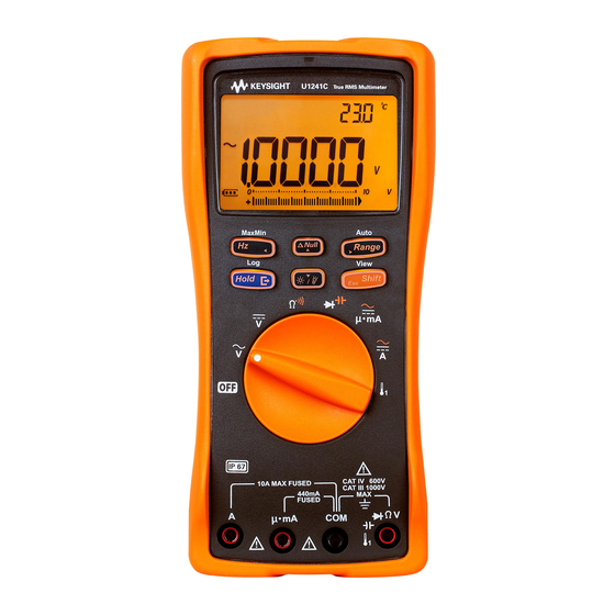
It will momentarily toggle the backlight on and off. Display test Press and turn on the multimeter to view all annunciators of the display. Hold Compare the display with the example in Figure 1-1. Figure 1-1 Display screen Keysight U1241C/U1242C Service Guide... -
Page 22: Input Warning Test (A Terminal)
CAT IV 600V 10A MAX FUSED CAT III 1000V 440mA FUSED Figure 1-2 Example of A-Er for wrong terminal input Before conducting this test, make sure the beep alert function is enabled in the NOTE Setup mode. Keysight U1241C/U1242C Service Guide... -
Page 23: Input Warning Test ( Terminal)
CAT IV 600V 10A MAX FUSED CAT III 1000V 440mA FUSED Figure 1-3 Example of μAEr for wrong terminal input Before conducting this test, make sure the beep alert function is enabled in the NOTE Setup mode. Keysight U1241C/U1242C Service Guide... -
Page 24: Calibration Process
– Use a shielded twisted pair of PTFE-insulated cables to reduce settling and noise errors. Keep the input cables as short as possible. Long test leads can also act as antennas which may pick up AC signals. – Connect the input cable shields to earth ground. Keysight U1241C/U1242C Service Guide... -
Page 25: Performance Verification Tests
Performance Verification Tests Use the performance verification tests to verify the measurement performance of the multimeter. The performance verification tests use the multimeter’s specifications listed in the U1241C/U1242C datasheet (http://literature.cdn.keysight.com/litweb/pdf/5992-0848EN.pdf). The performance verification tests are recommended as acceptance tests when you first receive the multimeter. -
Page 26: Dc V (V) Performance Verification Tests
Null function is used to subtract the thermal effect (by shorting the test leads) before measuring the signal. [b] Before turning the rotary switch, you must enable the mV measurement function from the Setup menu first. For enabling the mV measurement function from the Setup menu, refer to the U1241C/U1242C User’s Guide. Keysight U1241C/U1242C Service Guide... -
Page 27: Ac V (V) True Rms Performance Verification Tests
[a] The impedance may be set to >1 GΩ from the Setup mode; the default value is 10 MΩ in parallel with 100 pF (nominal). [b] Before turning the rotary switch, you must enable the mV measurement function from the Setup menu first. For enabling the mV measurement function from the Setup menu, refer to the U1241C/U1242C User’s Guide. Keysight U1241C/U1242C Service Guide... -
Page 28: Ac V (V) Averaging Sense Performance Verification Tests
[a] The impedance may be set to >1 GΩ from the Setup mode; the default value is 10 MΩ in parallel with 100 pF (nominal). [b] Before turning the rotary switch, you must enable the mV measurement function from the Setup menu first. For enabling the mV measurement function from the Setup menu, refer to the U1241C/U1242C User’s Guide. Keysight U1241C/U1242C Service Guide... -
Page 29: Dc Current (Μa.ma) Performance Verification Tests
[b] 10 A continuous, and the signal greater than 10 A ~ 19.999 A for 30 seconds maximum. After measuring current of >10 A, cool down the multimeter for the same measuring time you applied before performing low current measurement. Connect the calibrator outputs to the multimeter’s A and COM terminals CAUTION before applying 10 A. Keysight U1241C/U1242C Service Guide... -
Page 30: Ac Current (A) True Rms Performance Verification Tests
[b] 10 A continuous, and the signal greater than 10 A ~ 19.999 A for 30 seconds maximum. After measuring current of >10 A, cool down the multimeter for the same measuring time you applied before performing low current measurement. Connect the calibrator outputs to the multimeter’s A and COM terminals CAUTION before applying 10 A. Keysight U1241C/U1242C Service Guide... -
Page 31: Ac Current (A) Averaging Sense Performance Verification
Connect the calibrator outputs to the multimeter’s A and COM terminals CAUTION before applying 10 A. Table 1-9 Diode performance verification test Error from nominal 1 year 5520A/5522A Test function Range output U1241C U1242C Diode ±0.020 V ±0.020 V Turn the rotary switch to the position. Keysight U1241C/U1242C Service Guide... -
Page 32: Capacitance Performance Verification Tests
±0.41 MΩ 100 MΩ 100 MΩ ±3.03 MΩ ±3.03 MΩ Ω [a] The accuracy of the 1000 range is specified after Math Null, which is used to subtract the test lead resistance and the thermal effect. Keysight U1241C/U1242C Service Guide... -
Page 33: Frequency Performance Verification Tests
– To perform the measurement, connect one end of the K-type thermocouple (with miniature TC connector on both ends) to the 5520A TC output, and the other end to the multimeter via a TC-to-banana adapter. Allow at least 1 hour for the multimeter to stabilize. Keysight U1241C/U1242C Service Guide... -
Page 34: Calibration Security
The security code is stored in nonvolatile memory, and does not change when power has been turned off or after a remote interface reset. The security code may contain up to four numeric characters. Keysight U1241C/U1242C Service Guide... -
Page 35: Unsecuring The Multimeter For Calibration
Calibration security code 2 Enter the default security code to unsecure the multimeter. MaxMin Auto – Press to move the cursor to the left or right Range respectively. Vsense – Press to increment or decrement the digit respectively. Keysight U1241C/U1242C Service Guide... - Page 36 View 4 Exit the unsecured mode by pressing both together for Shift Hold more than 1 second to secure the multimeter again. Figure 1-5 for the multimeter’s display. Keysight U1241C/U1242C Service Guide...
- Page 37 Calibration Procedures View Press for >1 sec. Shift Hold Vsense MaxMin Auto Press , and Range to enter the values. After appearing briefly Press to confirm. Hold Fail Pass After appearing briefly Figure 1-5 Unsecuring the multimeter Keysight U1241C/U1242C Service Guide...
-
Page 38: To Change The Calibration Security Code
5 Record down your new calibration security code and store it in a safe location. View 6 Exit the unsecured mode by pressing both together for Shift Hold more than 1 second to secure the multimeter again. Figure 1-6 for the multimeter’s display. Keysight U1241C/U1242C Service Guide... - Page 39 View Press for >1 sec. Shift Vsense MaxMin Auto Press , and Range to enter the values. After appearing briefly Press to confirm. Hold Fail Pass After appearing briefly Figure 1-6 Changing the calibration security code Keysight U1241C/U1242C Service Guide...
-
Page 40: To Reset The Calibration Security Code To Its Factory Default
– To enter a new security code, see “To change the calibration security code” on page 38. Ensure that you record down the new security code. Figure 1-7 for the multimeter’s display. Keysight U1241C/U1242C Service Guide... - Page 41 >1 sec. Shift Vsense MaxMin Auto Press , and Range to enter the values. After appearing briefly Press to confirm. Hold Fail Pass After appearing briefly Figure 1-7 Resetting the calibration security code to its factory default Keysight U1241C/U1242C Service Guide...
-
Page 42: Using The Front Panel For Adjustments
Calibration error messages are described in “Calibration Error Codes” on page 54. Never turn off the multimeter during an adjustment. This may delete the CAUTION calibration memory for the present function. Keysight U1241C/U1242C Service Guide... -
Page 43: Rotary Switch Position For Calibration
Turn the rotary switch to the positions as indicated above for the following calibration functions: Table 1-14 Rotary switch positions for calibration Rotary switch position Calibration function AC V or Vsense DC V Resistance Diode or capacitance DC/AC μ.mA DC/AC A DC/AC mV or temperature Keysight U1241C/U1242C Service Guide... -
Page 44: Valid Adjustment Input Values
1000.0 V (1 kHz) 0.9 to 1.1 x Reference value 1000.0 V (10 kHz) 0.9 to 1.1 x Reference value Hi.10 V 10 V (55 Hz) High sense Vsense Lo.30 V 30 V (55 Hz) Low sense Keysight U1241C/U1242C Service Guide... - Page 45 100.00 kΩ 0.9 to 1.1 x Reference value 10.000 kΩ 10.000 kΩ 0.9 to 1.1 x Reference value 1000.0 Ω 1000.0 Ω 0.9 to 1.1 x Reference value Short SHor Short V Ω / COM terminals Keysight U1241C/U1242C Service Guide...
- Page 46 0.9 to 1.1 x Reference value 100.00 mA 100.00 mA (55 Hz) 0.9 to 1.1 x Reference value 030.0 mA (55 Hz) 0.7 to 1.3 x Reference value 1000.0 mA 300.0 mA (55 Hz) 0.9 to 1.1 x Reference value Keysight U1241C/U1242C Service Guide...
-
Page 47: Vsense (Non-Contact Voltage) Calibration
4 Ensure the top of the multimeter is vertically and horizontally centered to contact the banana plug's Hi terminal. 5 Set the source output to 10 V/55 Hz. 6 Press to start the calibration. If the calibration is successful, Hold will be displayed. Keysight U1241C/U1242C Service Guide... - Page 48 Calibration Procedures 7 Set the source output to 30 V/55 Hz. 8 Press to start the calibration. Hold 9 When the calibration has completed, set the calibrator to the standby mode. Figure 1-9 for the multimeter’s display. Keysight U1241C/U1242C Service Guide...
-
Page 49: Figure 1-9 Vsense (Non-Contact Voltage) Calibration
Calibration Procedures Press to start calibration. Hold Fail Pass After appearing briefly After appearing briefly Figure 1-9 Vsense (non-contact voltage) calibration Keysight U1241C/U1242C Service Guide... -
Page 50: Adjustment Procedure
54. 6 Repeat step 4 step 5 until calibration has completed for all calibration values. View 7 Press or turn the rotary switch to select other values to be calibrated. Shift Repeat step 6 step Keysight U1241C/U1242C Service Guide... -
Page 51: Exiting The Adjustment Mode
1 Remove all the shorting plugs and connectors from the multimeter. 2 Record the new calibration count. View 3 Press both together for more than 1 second to exit the Shift Hold calibration mode. 4 Cycle the multimeter’s power. The multimeter will then be secured. Keysight U1241C/U1242C Service Guide... -
Page 52: Calibration Count
1 second in the adjustment mode to view the calibration count. 2 Take note of the calibration count to keep track of the number of calibrations that have been performed. MaxMin 3 Press for more than 1 second to exit the calibration count mode. Keysight U1241C/U1242C Service Guide... -
Page 53: Figure 1-10 Calibration Count Mode
Calibration Procedures MaxMin Press for >1 sec. Figure 1-10 Calibration count mode Keysight U1241C/U1242C Service Guide... -
Page 54: Calibration Error Codes
Calibration error: calibration aborted 005/E005 Calibration error: value out of range, or signal measurement out of range 006/E006 Calibration error: signal measurement out of range 007/E007 Calibration error: frequency out of range 008/E008 EEPROM write failure Keysight U1241C/U1242C Service Guide... - Page 55 Keysight U1241C/U1242C Handheld Digital Multimeter Service Guide Service and Maintenance Troubleshooting Fuse Replacement Returning the Multimeter for Service Replaceable Parts Types of Service Available Obtaining Repair Service (Worldwide) This chapter will help you troubleshoot a failing multimeter. It also describes how...
-
Page 56: Service And Maintenance
✔ Verify the fuses health and replace the fuses as necessary. ✔ Verify the optical side of the IR-USB cable connected to the multimeter — the Keysight logo should be facing up. Failed on remote control ✔ Verify the baud rate, data bit, and parity settings in the multimeter’s Setup mode. -
Page 57: Fuse Replacement
OFF position. 1 Lift the tilt stand as shown on the right. 2 Loosen and remove the two screws with a suitable Phillips screwdriver as shown on the right. Keysight U1241C/U1242C Service Guide... - Page 58 Fuse 1 protecting terminal 7 Ensure that the inner cover is positioned properly. 8 Close the inner cover of the fuse compartment. 9 Place the fuse cover back in its original position and tighten the screws. Keysight U1241C/U1242C Service Guide...
-
Page 59: Returning The Multimeter For Service
Returning the Multimeter for Service Before shipping your multimeter for repair or replacement, Keysight recommends that you acquire the shipping instructions from the Keysight Service Center. A clear understanding of the shipping instructions is necessary to secure your multimeter for shipment. -
Page 60: Replaceable Parts
To order replaceable parts from Keysight, do the following: 1 Contact your nearest Keysight Sales Office or Service Center. 2 Identify the parts by the Keysight part number shown in the support parts list. 3 Provide the multimeter’s model number and serial number. -
Page 61: Types Of Service Available
Service and Maintenance Types of Service Available If your multimeter fails during the warranty period, Keysight will repair or replace it under the terms of your warranty. After your warranty expires, Keysight offers repair services at competitive prices. Extended service contracts Many Keysight products are available with optional service contracts that extend the covered period after the standard warranty expires. -
Page 62: Obtaining Repair Service (Worldwide)
Obtaining Repair Service (Worldwide) To obtain service for your multimeter (in-warranty, under service contract, or post-warranty), contact your nearest Keysight Service Center. They will arrange to have your unit repaired or replaced, and can provide warranty or repair-cost information where applicable. - Page 63 This information is subject to change without notice. Always refer to the Keysight website for the latest revision. © Keysight Technologies 2016-2017 Edition 5, April 21, 2017 Printed in Malaysia *U1241-90104* U1241-90104 www.keysight.com...
Need help?
Do you have a question about the U1242C and is the answer not in the manual?
Questions and answers