Winmate R15IB3S-PCC3-PoE User Manual
15 inch s-series hmi
intel celeron bay trail-m n2930 1.83 ghz
Hide thumbs
Also See for R15IB3S-PCC3-PoE:
- Quick start manual (36 pages) ,
- User manual (96 pages) ,
- User manual (92 pages)

Related Manuals for Winmate R15IB3S-PCC3-PoE


Summary of Contents for Winmate R15IB3S-PCC3-PoE
- Page 1 15"S-Series HMI Intel ® Celeron ® Bay Trail-M N2930 1.83 GHz Slim-line R15IB3S-PCC3-PoE User Manual Version 1.1 9152111I100T...
-
Page 2: Preface
USER MANUAL PREFACE PREFACE Copyright Notice No part of this document may be reproduced, copied, translated, or transmitted in any form or by any means, electronic or mechanical, for any purpose, without the prior written permission of the original manufacturer. Trademark Acknowledgement Brand and product names are trademarks or registered trademarks of their respective owners. - Page 3 USER MANUAL PREFACE Customer Service We provide a service guide for any problem by the following steps: First, visit the website of our distributor to find the update information about the product. Second, contact with your distributor, sales representative, or our customer service center for technical support if you need additional assistance.
- Page 4 USER MANUAL PREFACE Advisory Conventions Four types of advisories are used throughout the user manual to provide helpful information or to alert you to the potential for hardware damage or personal injury. These are Notes, Important, Cautions, and Warnings. The following is an example of each type of advisory.
-
Page 5: Safety Information
USER MANUAL PREFACE Safety Information WARNING! / AVERTISSEMENT! Always completely disconnect the power cord from your chassis whenever you work with the hardware. Do not make connections while the power is on. Sensitive electronic components can be damaged by sudden power surges. Only experienced electronics personnel should open the PC chassis. - Page 6 USER MANUAL PREFACE Safety Precautions For your safety carefully read all the safety instructions before using the device. Keep this user manual for future reference. Always disconnect this equipment from any AC outlet before cleaning. Do not use liquid or spray detergents for cleaning. Use a damp cloth. ...
- Page 7 USER MANUAL PREFACE *Let service personnel to check the equipment in case any of the following problems appear: o The power cord or plug is damaged. o Liquid has penetrated into the equipment. o The equipment has been exposed to moisture. o The equipment does not work well or you cannot get it to work according to the user manual.
- Page 8 USER MANUAL PREFACE Cover workstations with approved anti-static material. Use a wrist strap connected to a work surface and properly grounded tools and equipment. Use anti-static mats, heel straps, or air ionizer for added protection. Handle electrostatic-sensitive components, PCB’s and assemblies by the case or the edge of the board.
-
Page 9: Important Information
USER MANUAL PREFACE Important Information Countries/ Symbol This equipment complies with essential Area requirements of: FCC Part 15 Subpart B Regulations Class B European Electromagnetic Compatibility Union Directive(2014/30/EU) Low Voltage Directive (2014/35/EU) Restrictions of the use of certain hazardous substances (RoHS) Directive (2011/65/EU) Federal Communications Commission Radio Frequency Interface Statement This device complies with part 15 FCC rules. -
Page 10: Ec Declaration Of Conformity
USER MANUAL PREFACE EC Declaration of Conformity This equipment is in conformity with the requirement of the following EU legislations and harmonized standards. Product also complies with the Council directions. Electromagnetic Compatibility Directive (2014/30/EU) EN55024: 2010/ A1: 2015 o IEC61000-4-2: 2009 o IEC61000-4-3: 2006+A1: 2007+A2: 2010 o IEC61000-4-4: 2012 o IEC61000-4-5: 2014... -
Page 11: About This User Manual
ABOUT THIS USER MANUAL ABOUT THIS USER MANUAL This User Manual provides information about using the Winmate® Intel ® Celeron ® Bay Trail-M N2930 1.83GHz processor. The documentation set for the S -Series HMI provides information for specific user needs, and includes: ... -
Page 13: Table Of Contents
USER MANUAL CONTENTS CONTENTS PREFACE ........................ii ABOUT THIS USER MANUAL ..................i CHAPTER 1: INTRODUCTION ..................2 1.1 Product Features ....................2 1.2 Package Contents ....................3 1.3 Product Overview ....................5 1.4 Physical Buttons and LED Indicators ..............6 CHAPTER 2: GETTING STARTED ..................8 2.1 Powering On ....................... - Page 14 USER MANUAL CONTENTS 3.3 Using HF RFID Reader ..................20 3.4 How to Enable Watchdog ................23 3.5 Adjusting the LCD Display Brightness .............. 25 4 Driver Installation ....................27 4.1 Chipset Driver Installation ................27 4.2 Graphics Driver Installation ................29 4.3 Intel Sideband Fabric Device (Intel MBI) Driver Installation (Windows 8) ..
- Page 15 USER MANUAL CHAPTER 1 INTRODUCTION INTRODUCTION This chapter gives you product overview, describes features and hardware specification. You will find all accessories that come with the HMI device in the packing list. Mechanical dimensions and drawings included in this chapter. 15”...
-
Page 16: Chapter 1: Introduction
CHAPTER 1: INTRODUCTION Interactive and smart automation systems of intelligent buildings are in a fast growing phase. Winmate® S-Series HMI is suitable for home automation and room management systems. Flat surface is easy-to-clean and delivers aesthetically pleasing look for any interior. -
Page 17: Package Contents
USER MANUAL CHAPTER 1 INTRODUCTION 1.2 Package Contents Carefully remove the box and unpack your HMI device. Please check if all the items listed below are inside your package. If any of these items are missing or damaged contact us immediately. - Page 18 USER MANUAL CHAPTER 1 INTRODUCTION Package may include optional accessories based on your order: Front Side VESA Desk Stand VESA Wall Mount Bracket Wall Mount Kit LA-100 LA-106 PCFW-V2 9B0000000128 9B0000000412 99K000A00006. 15” S-SERIES HMI...
-
Page 19: Product Overview
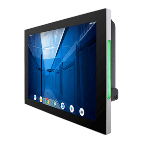
USER MANUAL CHAPTER 1 INTRODUCTION 1.3 Product Overview This section describes 15” S-Series HMI appearance and LED Indicators behavior. Unit: mm № Description № Description ① RJ-45 (LAN) ⑥ Digital I/O (Optional) ② USB 3.0 x 1 , USB 2.0 x 1 ⑦... -
Page 20: Physical Buttons And Led Indicators
USER MANUAL CHAPTER 1 INTRODUCTION 1.4 Physical Buttons and LED Indicators Physical buttons and LED indicators located on the rear side of the HMI. Physical Buttons Icon Button Description Reset Press to reset the system Power On/ Off Press to power on or power off the device LED Indicators LED Type Status... -
Page 21: Getting Started
USER MANUAL CHAPTER 2 GETTING STARTED Getting Started This chapter tells you important information on power supply, adapter and precautions tips. Pay attention to power considerations. 15” S-SERIES HMI... -
Page 22: Chapter 2: Getting Started
USER MANUAL CHAPTER 2 GETTING STARTED CHAPTER 2: GETTING STARTED This chapter provides information on how to connect the HMI device to the source of power, connector pinouts and the guideline to turn on/off the HMI device. 2.1 Powering On 2.1.1 AC Adapter Components Terminal Block to DC AC Adapter... -
Page 23: Power Considerations
USER MANUAL CHAPTER 2 GETTING STARTED ALTERNATING CURRENT / MISE À LE TERRE! This product must be grounded. Use only a grounded AC outlet. Install the additional PE ground wire if the local installation regulations require it. *If you do not use a grounded outlet while using the device, you may notice an electrical tingling sensation when the palms of your hands touch the device. -
Page 24: Connecting The Power
USER MANUAL CHAPTER 2 GETTING STARTED 2.1.3 Connecting the Power Installation Instruction: Connect HMI device (1) to a the AC adapter (2) Connect the AC adapter (2) to the power cord (3) Plug in the power cord (3) to a working AC wall outlet (4). The device will boot automatically. -
Page 25: Connector Pinouts
USER MANUAL CHAPTER 2 GETTING STARTED 2.2 Connector Pinouts 2.2.1 Power Connector DC power source input is a 3 pin terminal block connector. Minimum Voltage 11.4V Maximum Voltage 12.6V Maximum Current 4.2A Voltage 2.2.2 Ethernet Connector The 7” S-Series HMI has two RJ45 connectors that support 10/100/1000 Mbps Ethernet interface for connecting to the internet. -
Page 26: Usb 2.0 And Usb 3.0 Connector
USER MANUAL CHAPTER 2 GETTING STARTED 2.2.4 USB 2.0 and USB 3.0 Connector Pin № Signal Name Pin № Signal Name USB_D- USB_D+ STDA_SSRX- STDA_SSRX+ GND_DRAIN STDA_SSTX- STDA_SSTX+ USB_D- USB_D+ 2.2.5 Digital I/O Connector Notice that Digital I/O is an optional connector and may not be present in your model. Pin №... -
Page 27: Configuring Serial Port Settings
USER MANUAL CHAPTER 2 GETTING STARTED 2.6 Configuring Serial Port Settings Serial port COM1 can be configured for RS-232, RS-422 or RS-485.Jumpers are located on the motherboard. You need to open the housing in order to access the jumpers. CAUTION/ ATTENTION It is recommended to use factory jumper settings. -
Page 28: Turning On And Off
USER MANUAL CHAPTER 2 GETTING STARTED 2.7 Turning On and Off To Power ON the device: 1. Connect the AC adapter to the power cord. 2. Plug the power cord to an electrical outlet. 3. Press the Power button right above the device to turn on it. You can Turn OFF the HMI device with the Windows power settings. - Page 29 USER MANUAL CHAPTER 3 OPERATING THE DEVICE OPERATING THE DEVICE This chapter provides detailed information on how to operate the device. If you have been using touch-screen Panel PCs before, the interface may look familiar. Sections include system settings parameters. 15”...
-
Page 30: Chapter 3: Operating The Device
USER MANUAL CHAPTER 3 OPERATING THE DEVICE CHAPTER 3: OPERATING THE DEVICE In this chapter you will find instructions on how to operate the HMI device with Hot Tab. 3.1 Operating System S-series HMI support several versions of Windows OS: Windows 10 IoT, Windows Embedded 8.1 Industry Pro, Windows Embedded 8 Standard, Windows 7 Pro for Embedded Systems, and Windows Embedded Standard 7 –... -
Page 31: Utilities
USER MANUAL CHAPTER 3 OPERATING THE DEVICE 3.2.2 Utilities Utilities category allows automatically changing orientation from landscape to portrait mode or rotating the desktop to a different degree as 0°,90°, 180°, and 270°. 3.2.3 Brightness Tap Brightness button to show current brightness level. To reduce the brightness, drag by touch to the left. -
Page 32: Led Light Bar
USER MANUAL CHAPTER 3 OPERATING THE DEVICE 3.2.5 LED Light Bar Notice that LED Light Bar is an optional feature for 10.1” S-Series HMI and may not be present in your device. Tap Light Bar to access the LED light bar control panel, and select Red / Green / Blue/ Orange color to be displayed on the LED Bar. -
Page 33: Touch Lock
USER MANUAL CHAPTER 3 OPERATING THE DEVICE 3.2.7 Touch Lock To LOCK touch screen, double-click the Hot Tab icon on the Windows desktop, and tap Touch Lock. To UNLOCK the touch screen, tap button to the right. 15” S-SERIES HMI... -
Page 34: Using Hf Rfid Reader
USER MANUAL CHAPTER 3 OPERATING THE DEVICE 3.3 Using HF RFID Reader Notice that HF RFID Reader is an optional feature for 10.1” S-Series HMI and may not be present in your device. HF RFID is commonly used for ticketing, payment, and data transfer applications. The RFID Reader is located on the bottom right front side of the HMI device. - Page 35 USER MANUAL CHAPTER 3 OPERATING THE DEVICE Reader Demo Version 1.04 3.3.1 Reading Mode Select the default RFID Reader COM14or press Search on the upper left corner of the screen. The system will automatically find RFID COM port, show the Version. Item №...
- Page 36 USER MANUAL CHAPTER 3 OPERATING THE DEVICE UID0 Menu The system will read the data once the card will be near. You can select different reader modes. Each mode is described below. Item № Key button Function A0- Continuous The RFID Reader will perform a series of multiple Read (default) scanning operations A1- Once Read...
-
Page 37: How To Enable Watchdog
OPERATING THE DEVICE 3.4 How to Enable Watchdog To enable Watchdog, you need to download Winmate Watchdog utility. Find more information on Watchdog in “Watchdog Guide” that you can download from Winmate Download Center or File Share. Refer to the User Manual for more details. - Page 38 USER MANUAL CHAPTER 3 OPERATING THE DEVICE Settings Description The system automaticity restarts when this countdown time reaches zero. Watchdog Countdown Time Default: 10 min To set a cycle time to automatically reset watchdog Periodically Feed Time timer. Default: 9 min Enable / Disable Enable or disable watchdog.
-
Page 39: Adjusting The Lcd Display Brightness
USER MANUAL CHAPTER 3 OPERATING THE DEVICE 3.5 Adjusting the LCD Display Brightness 1. Open the All Control Panel Items, and click/tap on the Power Options. 2. At the bottom of Power Options, move the Screen brightness slider right (brighter) and left (dimmer) to adjust the screen brightness to whatever level you like. - Page 40 USER MANUAL CHAPTER 4 DRIVER INSTALLATION DRIVER INSTALLATION This chapter describes how to install all necessary drivers. 15” S-SERIES HMI...
-
Page 41: Driver Installation
USER MANUAL CHAPTER 4 DRIVER INSTALLATION 4 Driver Installation This chapter describes how to install all necessary drivers. 4.1 Chipset Driver Installation 1. Insert the CD that comes with the motherboard. Open the file document “Chipset Driver” and click “infinst_auto.exe” to install driver. 2. - Page 42 USER MANUAL CHAPTER 4 DRIVER INSTALLATION Click Yes to agree the license terms. 4. Click Next to install the driver. 5. Software setup progress window will appear, click Next to continue. 6. Click “Yes, I want to restart this computer now” to finish the installation. 15”...
-
Page 43: Graphics Driver Installation
USER MANUAL CHAPTER 4 DRIVER INSTALLATION 4.2 Graphics Driver Installation 1. Insert the CD that comes with the motherboard. Open the file document “Graphics Driver” and click Setup to execute the setup. 2. Setup Welcome Window will appear, click Next to continue the process. 1. -
Page 44: Intel Sideband Fabric Device (Intel Mbi) Driver Installation (Windows 8)
USER MANUAL CHAPTER 4 DRIVER INSTALLATION 4.3 Intel Sideband Fabric Device (Intel MBI) Driver Installation (Windows 8) 1. Insert the CD that comes with the motherboard. Open the file document “MBI” and click “Setup.exe” to install the driver. 2. Welcome to the setup program window will appear, click Next to start the installation. -
Page 45: Intel Trusted Engine Interface (Intel Txe) Driver Installation
USER MANUAL CHAPTER 4 DRIVER INSTALLATION 4.4 Intel Trusted Engine Interface (Intel TXE) Driver Installation 1. Insert the CD that comes with the motherboard. Open the file document “TXE” and click “Setup TXE.exe” to install the driver. 2. Welcome to the setup program window will appear, click Next to start the installation. -
Page 46: Intel Network Connections Installation
USER MANUAL CHAPTER 4 DRIVER INSTALLATION 4.5 Intel Network Connections Installation User must confirm the type of operating system is being used before installing Intel Network Connections. Follow the steps below to complete the installation. 1. Click “PROWin64.exe” 2. Click Yes to start the installation. 3. -
Page 47: Audio Driver Installation
USER MANUAL CHAPTER 4 DRIVER INSTALLATION 4.6 Audio Driver Installation The ALC886 series are high-performance 7.1+2 channel high definition audio codecs that provide ten DAC channels for simultaneous support of 7.1 sound playback, plus 2 channels of independent stereo sound output (multiple streaming) through the front panel stereo outputs. -
Page 48: Usb 3.0 Driver (Windows 7) Installation
USER MANUAL CHAPTER 4 DRIVER INSTALLATION 4.7 USB 3.0 Driver (Windows 7) Installation NOTE: If your operation system is Windows Embedded 8.1 Industry or Windows Embedded 8 Standard, you should skip the USB 3.0 driver installation. This HMI features Intel Celeron Trail-M N2930 CPU with the Intel®... -
Page 49: Bios Setup
USER MANUAL CHAPTER 5 BIOS SETUP BIOS SETUP BIOS Setup Utility is a program for configuration basic Input / Output system settings of the HMI for optimum use. This chapter provides information on how to use BIOS setup, its functions and menu. 15”... -
Page 50: Chapter 5: Bios Setup
USER MANUAL CHAPTER 5 BIOS SETUP CHAPTER 5: BIOS SETUP 5.1 When and How to Use BIOS Setup To enter the BIOS setup, you need to connect an external USB keyboard, press <Del> key when the prompt appears on the screen during start up. The prompt screen shows only few seconds, you need to press <Del>... -
Page 51: Bios Functions
USER MANUAL CHAPTER 5 BIOS SETUP 5.2 BIOS Functions BIOS Navigation Keys BIOS navigation keys for keyboard control are listed below. The following keys are enabled during POST: Function Enters the BIOS setup menu. Display the boot menu. Lists all bootable devices that are connected to the system. -
Page 52: Main Menu
USER MANUAL CHAPTER 5 BIOS SETUP 5.2.1 Main Menu When you enter BIOS setup, the first menu that appears on the screen is the main menu.It contains the system information including BIOS version, processor RC version, system language, time, and date. Immediately after the [DEL] key is pressed during startup, the main BIOS setup menu appears: BIOS Setting... -
Page 53: Advanced Menu
USER MANUAL CHAPTER 5 BIOS SETUP 5.2.2 Advanced Menu The advanced menu also uses to set configuration of the CPU and other system devices. There are sub menus on the left frame of the screen. IMPORTANT: Handle advanced BIOS settings page with caution. Any changes can affect the operation of your computer. - Page 54 USER MANUAL CHAPTER 5 BIOS SETUP BIOS Setting Description Setting Option Effect ACPI Settings Configures ACPI Enter Opens submenu settings F81866 Super IO Configures IO Enter Opens submenu Configuration settings Hardware Monitor Configures Enter Opens submenu Hardware Monitor settings S5 RTC Wake Configures RTC Enter Opens submenu...
- Page 55 USER MANUAL CHAPTER 5 BIOS SETUP 5.2.2.1 ACPI Settings Advanced Configuration and Power Interface (ACPI) settings allow to control how the power switch operates. The power supply can be adjusted for power requirements. You can use the screen to select options of ACPI configuration. A description of the selected items will appear on the right side of the screen.
- Page 56 USER MANUAL CHAPTER 5 BIOS SETUP 5.2.2.2 F81866 Super IO Configuration You can use the screen to select options for Super IO Configuration, and change the value of the option selected. A description of the selected item appears on the right side of the screen.
- Page 57 USER MANUAL CHAPTER 5 BIOS SETUP GPI0 Port Configuration You can use the screen to change GPI0 Port setting. Use these items to set parameters related to PIN3-PIN14 Control. 5.2.2.3 Hardware Monitor You can check PC Health Status parameters such as system temperature, fan speed etc. 15”...
- Page 58 USER MANUAL CHAPTER 5 BIOS SETUP 5.2.2.4 S5 RTC Wake Settings Wake system from S5 enables or disables system wake on alarm event. It allows you to wake up the system in a certain time. 15” S-SERIES HMI...
- Page 59 USER MANUAL CHAPTER 5 BIOS SETUP Wake System from S5 with fixed time setting Select Fixed Time to set the system to wake on the specified time. Use Navigation Keys to switch among the items: Day, Hour, Minute and Second. Type the desired value in the selected item. For example: If you want the system to start up automatically at 15:30:30, the 10th day of each month, then you should enter 10, 15, 30, and 30 from top to bottom.
- Page 60 USER MANUAL CHAPTER 5 BIOS SETUP Wake system from S5 after dynamic time setting Select Dynamic Time to set the system to wake on the current time + increase minute (s). 15” S-SERIES HMI...
- Page 61 USER MANUAL CHAPTER 5 BIOS SETUP 5.2.2.5 CPU Configuration BIOS Setting Description Setting Option Effect Socket CPU This item contains Enter Open sub-menu Information socket specific CPU information. CPU Thermal Thermal control Enter Open sub-menu Configuration Limit CPUID Limits CPIID Disabled/Enabled Enable/Disable this Maximum...
- Page 62 USER MANUAL CHAPTER 5 BIOS SETUP 5.2.2.6 PPM Configuration BIOS Setting Description Setting Option Effect CPU C State Report Shows CPU C State Enabled/ Enable or Disable Report Disabled CPU C state report to OS Max CPU C-State Allows to enter C1E, C3, C6, C7, Enable or Disable power-saving...
- Page 63 USER MANUAL CHAPTER 5 BIOS SETUP 5.2.2.7 Thermal Configuration This menu allows controlling thermal settings of the computer. Refer to the descriptions on the top right side of the screen for detailed information about each setting. BIOS Setting Description Setting Option Effect Critical Trip Point Specifies the...
- Page 64 USER MANUAL CHAPTER 5 BIOS SETUP 5.2.2.8 IDE Configuration BIOS Setting Description Setting Option Effect Serial- ATA (SATA) Responsible for Enabled/ Enable or disable supporting chipset Disabled this function drives with SATA interface. SATA Speed Allows forcing the Gen1 The maximum Support speed limit SATA II speed will be...
- Page 66 USER MANUAL CHAPTER 5 BIOS SETUP SATA Mode This option specifies [AHCI] Selecting this the operation mode option allows you of modern IDE / to take full SATA-controller advantage of the chipset extended host controller SATA II [IDE] SATA controller will operate in a mechanism similar to a...
- Page 67 USER MANUAL CHAPTER 5 BIOS SETUP 5.2.2.9 Miscellaneous Configuration OS Selection This item allows users to select the proper Operating System. BIOS Setting Description Setting Option Effect Windows 8.X Allows user to Enter Use Windows 8.X choose the proper Windows 7 Allows user to Enter Use Windows 7...
- Page 68 USER MANUAL CHAPTER 5 BIOS SETUP 5.2.2.10 CSM Configuration 15” S-SERIES HMI...
- Page 69 USER MANUAL CHAPTER 5 BIOS SETUP BIOS Setting Description Setting Option Effect CSM Support The Compatibility Support Enabled/ Enable or disable Module (CSM) is a Disabled the Compatibility component of the UEFI Support Module firmware that provides legacy BIOS compatibility by emulating a BIOS environment, allowing legacy operating systems and some...
- Page 70 USER MANUAL CHAPTER 5 BIOS SETUP 5.2.2.11 USB Configuration BIOS Setting Description Setting Option Effect Legacy USB Support User can enable or Disable Will keep USB disable USB port. devices available only for EFI applications. Enable Enable all the USB devices USB 3.0 Support User can enable or...
- Page 72 USER MANUAL CHAPTER 5 BIOS SETUP XHCI Hand‐off This is a Disable Disables this workaround for function OSs without XHCI Enable Enables this hand‐ off support. function EHCI Hand‐off This is a Disable Disables this workaround for function OSs without ECHI Enable Enables this hand‐...
- Page 73 USER MANUAL CHAPTER 5 BIOS SETUP 5.2.2.12 Platform Trust Technology BIOS Setting Description Setting Option Effect fTPM Trusted Platform Enabled/Disabled Enables or Module parameters disables this function 15” S-SERIES HMI...
- Page 74 USER MANUAL CHAPTER 5 BIOS SETUP 5.2.2.13 Security Configuration BIOS Setting Description Setting Option Effect Trusted Execution Enabled/Disabled Enables or disables Technology this function parameters TXE HMRFPO TXE HMRFPO Enabled/Disabled Enables or disables parameters this function TXE Firmware TXE Firmware Enabled/Disabled Enables or disables Update...
-
Page 75: Chipset Menu
USER MANUAL CHAPTER 5 BIOS SETUP 5.2.3 Chipset Menu BIOS Setting Description Setting Option Effect High Precious Allow to set up Enabled/ Enables/Disables Timer High Precious Disabled this function Timer settings Restore AC Power This function allows Power on/ Boot automatically Loss to set up booting Power off... -
Page 76: Security Menu
USER MANUAL CHAPTER 5 BIOS SETUP 5.2.4 Security Menu In the Security menu, users can set administrator password, user password, and HDD security configuration. BIOS Setting Description Setting Option Effect Administrator Displays whether Enter Enter password Password or not an administrator password has been set. -
Page 77: Boot Configuration
USER MANUAL CHAPTER 5 BIOS SETUP 5.2.5 Boot Configuration The Boot menu sets the sequence of the devices to be searched for the operating system. The bootable devices will be automatically detected during POST and shown here, allowing you to set the sequence that the BIOS uses to look for a boot device from which to load the operating system. - Page 78 USER MANUAL CHAPTER 5 BIOS SETUP BIOS Setting Description Setting Option Effect Setup Prompt Allows user to Enter Set the prompt Timeout configure the timeout number of seconds to stay in BIOS setup prompt screen. Boot NumLock Enables or disables Remains On State NumLock feature...
-
Page 79: Save & Exit
USER MANUAL CHAPTER 5 BIOS SETUP 5.2.6 Save & Exit The Exit menu displays a way how to exit BIOS Setup utility. After finishing your settings, you must save and exit for changes to be applied. 15” S-SERIES HMI... - Page 80 USER MANUAL CHAPTER 5 BIOS SETUP BIOS Setting Description Setting Option Effect Save Changes and This saves the Enter <YES> Save changes Exit changes to the CMOS and exits the BIOS Setup program. Discard Changes This exits the BIOS Enter <YES> Saves the changes and Exit Setup without...
-
Page 81: Using Recovery Wizard To Restore Computer
USER MANUAL CHAPTER 5 BIOS SETUP 5.3 Using Recovery Wizard to Restore Computer Note: Before starting the recovery process, make sure to backup all user data. The data will be lost after the recovery process. To enable quick one-key recovery procedure: ... - Page 82 USER MANUAL CHAPTER 6 MOUNTING MOUNTING This chapter provides step-by-step mounting guide for all available mounting options. 15” S-SERIES HMI...
-
Page 83: Chapter 6: Mounting
USER MANUAL CHAPTER 6 MOUNTING CHAPTER 6: MOUNTING This chapter provides mounting guide for all available mounting options. Pay attention to cautions and warning to avoid any damages. 6.1 Cable Mounting Considerations For a nice look and safe installation, make sure cables are neatly hidden behind the HMI device. -
Page 84: Mounting Guide
USER MANUAL CHAPTER 6 MOUNTING 6.3 Mounting Guide S-series HMI devices come with different mounting options suitable for most of the industrial and commercial applications. S-series HMI devices come with different mounting options suitable for most of the industrial and commercial applications. 6.3.1 Panel Mounting Wall cutout Screw hole diameter... -
Page 85: Vesa Mounting
USER MANUAL CHAPTER 6 MOUNTING 6.3.2 VESA Mounting 6.3.2.1 VESA Desk Stand LA-100 The HMI device can be installed on a desk with the stand. You can purchase desk stand as an optional accessory. Mounting Instruction Use provided Philips M4x5 screws to fix the desk stand to VESA holes on the back cover of the device. - Page 86 USER MANUAL CHAPTER 6 MOUNTING 6.3.2.2 VESA Wall Mount Bracket LA-106 The HMI device can be installed on a desk with the stand. You can purchase desk stand as an optional accessory. Model Name: LA-106 Part Number: 9B0000000412 Mounting Instruction Accessories 15”...
- Page 87 USER MANUAL CHAPTER 6 MOUNTING Dimensions 15” S-SERIES HMI...
-
Page 88: Front Side Wall Mounting
USER MANUAL CHAPTER 6 MOUNTING 6.3.3 Front Side Wall Mounting You can purchase Front Side Wall Mount Bracket from Winmate as an optional accessory for 15” S-Series HMI. Model Name:PCFW-V2 Part Number: 99K000A00006. Mounting Instruction 1. Attach one part of the mounting bracket to the device; fix the bezel with Philips M4x5 screws. - Page 89 USER MANUAL CHAPTER 6 MOUNTING Dimensions 15” S-SERIES HMI...
-
Page 90: Technical Support
USER MANUAL CHAPTER 7 TECHNICAL SUPPORT Technical Support This chapter includes Technical Support and Software Development Kit (SDK). 15” S-SERIES HMI... -
Page 91: Chapter 7: Technical Support
7.1 Software Developer Support We provide the SDK in the User Manual and SDK CD, or you can download the SDK from Winmate Download Center Winmate File Share. -
Page 92: Problem Report Form
USER MANUAL CHAPTER 7 TECHNICAL SUPPORT 7.2 Problem Report Form 15" S-Series HMI (Slim-line) Customer name: Company: Tel.: Fax: E-mail: Date: Product Serial Number: ____________________________________________________ Problem Description: Please describe the problem as clearly as possible. Detailed description of the occurred problem will allow us to find the best solution to solve the problem as soon as possible. -
Page 93: Product Specifications
USER MANUAL APPENDIX A PRODUCT SPECIFICATIONS PRODUCT SPECIFICATIONS This section includes product specifications. Appendix 15” S-SERIES HMI... -
Page 94: Appendix A: Product Specifications
USER MANUAL APPENDIX A PRODUCT SPECIFICATIONS APPENDIX A: PRODUCT SPECIFICATIONS HMI Device Specifications Model Name R15IB3S-PCC3-PoE Size 15" TFT (Widescreen) Resolution 1024 x 768 Brightness 250 nits Display Max Colors 262K (6 bit) Touch Projected Capacitive Multi-Touch (P-CAP) Intel ® Celeron ® Bay Trail-M N2930 1.83GHz System Chipset Intel®... - Page 95 USER MANUAL APPENDIX A PRODUCT SPECIFICATIONS 1 x RJ 45-10/100/1000 Mbps (LAN) Ethernet Port 1 x RJ 45-10/100/1000 Mbps (LAN/ PoE) Digital I/O Digital /O Terminal Block 10-pin (Optional) Audio Output 1 Watt Speaker x 2 LED Status Light Built-in RGB LED Light Bar Peripheral (Optional) RFID Reader...
- Page 96 Winmate Inc. 9F, No.111-6, Shing-De Rd., San-Chung District, New Taipei City 24158, Taiwan, R.O.C Tel: 886-2-8511-0288 Fax: 886-2-8511-0211 Email: sales@winmate.com.tw Official website: www.winmate.com...
Need help?
Do you have a question about the R15IB3S-PCC3-PoE and is the answer not in the manual?
Questions and answers