Table of Contents

Related Manuals for Winmate G-WIN GC Series


Summary of Contents for Winmate G-WIN GC Series
- Page 1 7”~23.8” G-WIN Panel PC Intel® Celeron® N2930 GC Series User Manual Document Version 1.1 Document Part No. 91521110105A Please read these instructions carefully before using this product, and save this manual for future use.
-
Page 2: Table Of Contents
G-WIN GC Series Panel PC Contents Preface About This User Manual Chapter 1: Introduction 1.1 Overview 1.2 Features 1.3 Package Content 1.4 Product Overview Chapter 2: Getting Started 2.1 Turning On and Off Your Device 2.2 Operating the Panel PC 2.3 How to Enable Watchdog... -
Page 3: Preface
Preface Preface Copyright Notice No part of this document may be reproduced, copied, translated, or transmitted in any form or by any means, electronic or mechanical, for any purpose, without the prior written permission of the original manufacturer. Trademark Acknowledgement Brand and product names are trademarks or registered trademarks of their respective owners. -
Page 4: Safety Information
G-WIN GC Series Panel PC Advisory Conventions Four types of advisories are used throughout the user manual to provide helpful information or to alert you to the potential for hardware damage or personal injury. These are Notes, Important, Cautions, and Warnings. The following is an example of each type of advisory. - Page 5 Preface For your safety carefully read all the safety instructions before using the device. Keep this user manual for future reference. Always disconnect this equipment from any AC outlet before cleaning. Do not use liquid or spray detergents for cleaning. Use a damp cloth. ...
-
Page 6: Important Information
G-WIN GC Series Panel PC Turn off power and input signals before connecting test equipment. Keep the work area free of non-conductive materials, such as ordinary plastic assembly aids and Styrofoam. Use filed service tools, such as cutters, screwdrivers that are conductive. -
Page 7: About This User Manual
About This User Manual About This User Manual This User Manual provides information about using the Winmate® G-WIN GC Series Panel PC. This User Manual applies to the GC Series Panel PC. The documentation set for the GC Series Panel PC provides information for specific user needs, and includes: ... -
Page 8: Chapter 1: Introduction
G-WIN GC Series Panel PC Chapter 1: Introduction This chapter gives you product overview, describes features and hardware specification. You will find all accessories that come with the panel PC in the packing list. Mechanical dimensions and drawings included in this... -
Page 9: Overview
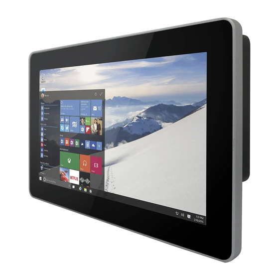
1.1 Overview Congratulations on purchasing Winmate® GC65 Panel PC. The elegantly designed, yet rugged, industrial grade G-WIN GC series is designed for heavy duty applications. With rugged construction, ultimate computing power, GC65 series are guaranteed to meet "heavy duty" needs. This series feature high computing power and user-friendly interface with projected capacitive multi-touch (PCAP) technology and support Windows®... -
Page 10: Product Overview
G-WIN GC Series Panel PC 1.4 Product Overview 7”, W07IB3S-GCO1 Unit: mm № № Description Description ① ⑤ 1x RS232/422/485 (Default RS232) 12V DC in Power Jack ② ⑥ 1 x USB 3.0, 1 x USB 2.0 OSD Control Panel ③... - Page 11 Chapter 1: Introduction 10.4”, R10IB3S-GCT2(HB) Unit: mm № № Description Description ① ④ 1x RS232/422/485 (Default RS232) 2 x RJ 45-10/100/1000 Mbps ② ⑤ 1 x USB 3.0, 1 x USB 2.0 12V DC in Power Jack ③ ⑥ 1 x HDMI 1.4a OSD Control Panel 12.1”, R12IB3S-GCM2(HB) Unit: mm...
- Page 12 G-WIN GC Series Panel PC 15”, R15IB3S-GCC3(HB) Unit: mm № № Description Description ① ⑤ 1x RS232/422/485 (Default RS232) 12V DC in Power Jack ② 1 x USB 3.0, 1 x USB 2.0 ⑥ OSD Control Panel ③ ⑦ 1 x HDMI 1.4a 2 Watt Speaker ④...
- Page 13 Chapter 1: Introduction 21.5”, W22IB3S-GCA3 Unit: mm № № Description Description ① ⑤ 1x RS232/422/485 (Default RS232) 12V DC in Power Jack ② ⑥ 1 x USB 3.0, 1 x USB 2.0 OSD Control Panel ③ ⑦ 1 x HDMI 1.4a 2 Watt Speaker ④...
-
Page 14: Chapter 2: Getting Started
G-WIN GC Series Panel PC Chapter 2: Getting Started This chapter tells you important information on power supply, adapter and precautions tips. Pay attention to power considerations. -
Page 15: Turning On And Off Your Device
Chapter 2: Getting Started 2.1 Turning On and Off Your Device Follow the following steps to turn on your device: 1. Connect the Panel PC to a thermal block (3-pin). 2. Connect the other side of the thermal block to the AC adapter. 3. -
Page 16: Operating The Panel Pc
OS settings. 2.3 How to Enable Watchdog To enable Watchdog, you need to download Winmate Watchdog utility. Find more information on Watchdog in “Watchdog Guide” that you can download from Winmate Download Center or File Share. -
Page 17: Configuring Serial Port Settings
Chapter 2: Getting Started Settings Description The system automaticity restarts when this countdown time reaches zero. Watchdog Countdown Time Default: 10 min To set a cycle time to automatically reset watchdog timer. Periodically Feed Time Default: 9 min Enable or disable watchdog. Enable / Disable Default: Enable 2.4 Configuring Serial Port Settings... -
Page 18: Chapter 3: Installation
G-WIN GC Series Panel PC Chapter 3: Installation This chapter provides instructions how to connect the panel PC to external interfaces. -
Page 19: Wiring Requirements
Chapter 3: Installation 3.1 Wiring Requirements The following common safety precautions should be observed before installing any electronic device: Strive to use separate, non-intersecting paths to route power and networking wires. If power wiring and device wiring paths must cross make sure the wires are perpendicular at the intersection point. - Page 20 G-WIN GC Series Panel PC Terminal Block Panel PC has DC power source input is a 3 pin terminal block connector. Minimum Voltage 11.4V Maximum Voltage 12.6V Maximum Current 4.2A Voltage 3.2.2 Serial Port Connector Use COM1 serial port connector to connect your Panel PC to external devices such as modem or printer.
- Page 21 Chapter 3: Installation 3.2.4 USB 2.0 and USB 3.0 Connector Use USB 2.0 and USB 3.0 connector to connect your GC65 Panel PC to other USB 2.0/ USB 3.0 compatible devices. USB2.0 and USB 3.0 Pin № Pin № Signal Name Signal Name USB_D- USB_D+...
-
Page 22: Chapter 4: Mounting
G-WIN GC Series Panel PC Chapter 4: Mounting This chapter provides mounting guide for all available mounting options. Pay attention to cautions and warning to avoid any damages. -
Page 23: Ram Mount
Chapter 4: Mounting 4.1 RAM Mount Notice that only 7” model support RAM Mounting to fit any vehicle application. *The picture is for demonstration purposes only. RAM Mounting accessories are not supplied by Winmate. -
Page 24: Vesa Mount
G-WIN GC Series Panel PC 4.2 VESA Mount This device supports VESA Mounting and provides various types of mounting options to fit any industrial use or vehicle. Size VESA Plate 7”, 10.1”, 10.4”, 12.1” 75x75 mm 10.4”, 15”, 19”, 21.5”, 23.8”... -
Page 25: Panel Mount
Chapter 4: Mounting 4.3 Panel Mount Panel Mount mounting solutions is suitable for many applications where Panel PC should be embedded. With this mounting solution flat surface leave no bezel in the front. Size Wall Cutout Screw Hole Diameter 7” 174.4 x 130.4, mm M4x4, mm 10.1”... -
Page 26: Chapter 5: Bios Setup
G-WIN GC Series Panel PC Chapter 5: BIOS Setup BIOS Setup Utility is a program for configuration basic Input/ Output system settings of the Panel PC for optimum use. This chapter provides information on how to use BIOS setup, its functions and menu. -
Page 27: When And How To Use Bios Setup
Chapter 5: BIOS Setup 5.1 When and How to Use BIOS Setup To enter the BIOS setup, you need to connect an external USB keyboard, press <Del> key when the prompt appears on the screen during start up. The prompt screen shows only few seconds, you need to press <Del>... -
Page 28: Bios Settings
G-WIN GC Series Panel PC 5.3 BIOS Settings 5.3.1 Main Menu When you enter BIOS setup, the first menu that appears on the screen is the main menu.It contains the system information including BIOS version, processor RC version, system language, time, and date. -
Page 29: Advanced Menu
Chapter 5: BIOS Setup 5.3.2 Advanced Menu The advanced menu also uses to set configuration of the CPU and other system devices. There are sub menus on the left frame of the screen. Important: Handle advanced BIOS settings page with caution. Any changes can affect the operation of your computer. - Page 30 G-WIN GC Series Panel PC BIOS Setting Description Setting Effect Option ACPI Settings Configures ACPI settings Enter Opens submenu F81866 Super IO Configures IO settings Enter Opens Configuration submenu Hardware Monitor Configures Hardware Monitor settings Enter Opens submenu S5 RTC Wake Settings...
- Page 31 Chapter 5: BIOS Setup 5.3.2.1 ACPI Settings Advanced Configuration and Power Interface (ACPI) settings allow to control how the power switch operates. The power supply can be adjusted for power requirements. You can use the screen to select options of ACPI configuration. A description of the selected items will appear on the right side of the screen.
- Page 32 G-WIN GC Series Panel PC 5.3.2.2 F81866 Super IO Configuration You can use the screen to select options for Super IO Configuration, and change the value of the option selected. A description of the selected item appears on the right side of the screen.
- Page 33 Chapter 5: BIOS Setup Watch Dog Time Select You can either disable Watch Dog Timer or set up the time.Use <Arrow> keys to navigate and please press <Enter>to select the item. GPI0 Port Configuration You can use the screen to change GPI0 Port setting. Use these items to set parameters related to PIN3-PIN14 Control.
- Page 34 G-WIN GC Series Panel PC 5.3.2.3 Hardware Monitor You can check PC Health Status parameters such as system temperature, fan speed etc. 5.3.2.4 S5 RTC Wake Settings Wake system from S5 enables or disables system wake on alarm event. It allows you to wake up the system in a certain time.
- Page 35 Chapter 5: BIOS Setup Wake System from S5 with fixed time setting Select Fixed Time to set the system to wake on the specified time. or example: If you want the system to start up automatically at 15:30:30, the 10th day of each month, then you should enter 10, 15, 30, and 30 from top to bottom.
- Page 36 G-WIN GC Series Panel PC 5.3.2.5 CPU Configuration BIOS Setting Description Setting Effect Option Socket CPU This item contains socket specific Enter Open sub-menu Information CPU information. CPU Thermal Thermal control Enter Open sub-menu Configuration Limit CPUID Limits CPIID Maximum...
- Page 37 Chapter 5: BIOS Setup 5.3.2.6 PPM Configuration BIOS Setting Description Setting Effect Option CPU C State Shows CPU C State Report Enabled/ Enable or Disable CPU Report Disabled C state report to OS Max CPU C-State Allows to enter power-saving C1E, C3, C6, Enable or Disable CPU mode in order to save energy...
- Page 38 G-WIN GC Series Panel PC 5.3.2.7 Thermal Configuration This menu allows controlling thermal settings of the computer. Refer to the descriptions on the top right side of the screen for detailed information about each setting. BIOS Setting Description Setting Option...
- Page 39 Chapter 5: BIOS Setup 5.3.2.8 IDE Configuration...
- Page 40 G-WIN GC Series Panel PC BIOS Setting Description Setting Effect Option Serial- ATA Responsible for Enabled/ Enable or disable this (SATA) supporting chipset drives Disabled function with SATA interface. SATA Speed Allows forcing the speed Gen1 The maximum speed will be...
- Page 41 Chapter 5: BIOS Setup 5.3.2.9 Miscellaneous Configuration OS Selection This item allows users to select the proper Operating System. BIOS Setting Description Setting Option Effect Windows 8.X Allows user to choose the Enter Use Windows 8.X proper OS. Windows 7 Allows user to choose the Enter Use Windows 7...
- Page 42 G-WIN GC Series Panel PC 5.3.2.10 CSM Configuration BIOS Setting Description Setting Effect Option CSM Support The Compatibility Support Module is a Enabled/ Enable or disable the component of the UEFI firmware that Disabled Compatibility Support provides legacy BIOS compatibility by...
- Page 43 Chapter 5: BIOS Setup 5.3.2.11 USB Configuration BIOS Setting Description Setting Effect Option Legacy USB User can enable or disable USB Disable Will keep USB devices Support port. available only for EFI applications. Enable Enable all the USB devices USB 3.0 Support User can enable or disable USB 3.0 Enable Enable USB 3.0 is enable...
- Page 44 G-WIN GC Series Panel PC 5.3.2.12 Security Configuration BIOS Setting Description Setting Effect Option Trusted Execution Technology Enabled/Di Enables or disables parameters sabled this function TXE HMRFPO TXE HMRFPO parameters Enabled/Di Enables or disables sabled this function TXE Firmware TXE Firmware Update parameters...
-
Page 45: Chipset Menu
Chapter 5: BIOS Setup 5.3.3 Chipset Menu For items marked with ►, please press <Enter> for more options. BIOS Setting Description Setting Option Effect High Precious Allow to set up High Precious Timer Enabled/ Enables/Disables Timer settings Disabled this function Restore AC This function allows to set up booting Power on/... -
Page 46: Security Menu
G-WIN GC Series Panel PC 5.3.4 Security Menu In the Security menu, users can set administrator password, user password, and HDD security configuration. BIOS Setting Description Setting Effect Option Administrator Displays whether or not an Enter Enter Password administrator password has been set. - Page 47 Chapter 5: BIOS Setup BIOS Setting Description Setting Effect Option Setup Prompt Allows user to configure the number of Enter Set the prompt timeout Timeout seconds to stay in BIOS setup prompt screen. Boot NumLock Enables or disables NumLock feature on Remains On State the numeric keypad of the keyboard after...
- Page 48 G-WIN GC Series Panel PC 5.3.6 Save& Exit The Exit menu displays a way how to exit BIOS Setup utility. After finishing your settings, you must save and exit for changes to be applied.
- Page 49 Chapter 5: BIOS Setup BIOS Setting Description Setting Effect Option Save Changes This saves the changes to the CMOS Enter <YES> Save changes and Exit and exits the BIOS Setup program. Discard This exits the BIOS Setup without Enter <YES> Saves the changes Changes and saving the changes made in BIOS...
-
Page 50: Using Recovery Wizard To Restore Computer
G-WIN GC Series Panel PC 5.4 Using Recovery Wizard to Restore Computer Note: Before starting the recovery process, make sure to backup all user data. The data will be lost after the recovery process. To enable quick one-key recovery procedure: ... -
Page 51: Chapter 6: Driver Installation
Chapter 6: Driver Installation Chapter 6: Driver Installation This chapter describes how to install all necessary drivers. -
Page 52: Installing Chipset Driver
G-WIN GC Series Panel PC 4.1 Installing Chipset Driver Step 1 Insert the CD that comes with the motherboard. Open the file document “Chipset Driver” and click “infinst_auto.exe” to install driver. Step 2 Click Next to continue. - Page 53 Chapter 6: Driver Installation Step 3 Click Yes to agree the license terms. Step 4 Click Next to install the driver. Step 5 Software setup progress window will appear, click Next to continue. Step 6 Click “Yes, I want to restart this computer now” to finish the installation.
-
Page 54: Installing Graphics Driver
G-WIN GC Series Panel PC 4.2 Installing Graphics Driver Step 1 Insert the CD that comes with the motherboard. Open the file document “Graphics Driver” and click Setup to execute the setup. Step 2 Setup Welcome Window will appear, click Next to continue the process. -
Page 55: Installing Intel Sideband Fabric Device (Intel Mbi)
Chapter 6: Driver Installation 4.3 Installing Intel Sideband Fabric Device (Intel MBI) Only for Windows 8 OS. Step 1 Insert the CD that comes with the motherboard. Open the file document “MBI” and click “Setup.exe” to install the driver. Step 2 Welcome to the setup program window will appear, click Next to start the installation. Step 3 Carefully read the License Agreement terms and click Yes to agree. -
Page 56: Installing Intel Trusted Engine Interface (Txe) Driver
G-WIN GC Series Panel PC 4.4 Installing Intel Trusted Engine Interface (TXE) Driver Step 1 Insert the CD that comes with the motherboard. Open the file document “TXE” and click “Setup TXE.exe” to install the driver. Step 2 Welcome to the setup program window will appear, click Next to start the installation. -
Page 57: Installing Intel Network Connections
Chapter 6: Driver Installation 4.5 Installing Intel Network Connections User must confirm the type of operating system is being used before installing Intel Network Connections. Follow the steps below to complete the installation. Step 1 Click “PROWin64.exe” Step 2 Click Yes to start the installation. Step 3 Welcome window will appear, click Next to install the driver. -
Page 58: Installing Audio Driver
G-WIN GC Series Panel PC 4.6 Installing Audio Driver The ALC886 series are high-performance 7.1+2 channel high definition audio codecs that provide ten DAC channels for simultaneous support of 7.1 sound playback, plus 2 channels of independent stereo sound output (multiple streaming) through the front panel stereo outputs. -
Page 59: Installing Usb 3.0 Driver
Chapter 6: Driver Installation 4.7 Installing USB 3.0 Driver Only for Windows 7 OS. NOTE: If your operation system is Windows Embedded 8.1 Industry or Windows Embedded 8 Standard, you should skip the USB 3.0 driver installation. This Panel PC features Intel Celeron Bay Trail-M N2930 CPU with the Intel® USB 3.0 extensible Host Controller. -
Page 60: Appendix
G-WIN GC Series Panel PC Appendix Appendix A: Specifications Model Name W07IB3S- W10IB3S- R10IB3S- R12IB3S- R15IB3S- GCO1 GCH1(HB) GCT2(HB) GCM2(HB) GCC3(HB) Display 10.1” TFT (Wide) 10.4” TFT 12.1” TFT 15” TFT Size/Type 7" TFT (Wide) Resolution 1024 x 600 1024 x 600... - Page 61 Appendix Model Name R19IB3S-GCM1 W22IB3S-GCA3 W24IB3S-GCA2 Display 21.5” TFT 23.8” TFT Size/Type 19" TFT Resolution 1280x1024 1920x1080 1920x1080 Brightness 250cd/m2 (typ.) 250cd/m2 (typ.) 250cd/m2 (typ.) Contrast Ratio 1000 : 1 (typ.) 3000 : 1 (typ.) 3000 : 1 (typ.) Viewing Angle -85~85(H);-80~80(V) -89~89(H);-89~89(V) -89~89(H);-89~89(V)
-
Page 62: Appendix B: Cleaning The Monitor
G-WIN GC Series Panel PC Appendix B: Cleaning the Monitor Before cleaning: Make sure the device is turned off. Disconnect the power cable from any AC outlet. When cleaning: Never spray or pour any liquid directly on the screen or case. -
Page 63: Appendix C: Winmate Software Development Kit
Appendix Appendix C: Winmate Software Development Kit Winmate® provides Software Development Kit (SDK). The table below lists SDK provided by Winmate for GC Series Panel PC with Intel ® Celeron ® Bay Trail-M N2930 processor: Item File Type Description Watchdog SDK... - Page 64 Winmate Inc. 9F, No.111-6, Shing-De Rd., San-Chung District, New Taipei City 24158, Taiwan, R.O.C www.winmate.com Copyright © Winmate Inc. All rights reserved.
Need help?
Do you have a question about the G-WIN GC Series and is the answer not in the manual?
Questions and answers