Table of Contents
Advertisement
Quick Links
Download this manual
See also:
User Manual
Advertisement
Table of Contents

Related Manuals for Extron electronics DP DA2


Summary of Contents for Extron electronics DP DA2
- Page 1 User Guide DisplayPort DP DA2 Distribution Amplifier 68-2154-01 Rev. A 07 12...
- Page 2 Safety Instructions • English Warning Power sources • This equipment should be operated only from the power source indicated on the product. This This symbol is intended to alert the user of important operating and mainte- equipment is intended to be used with a main power system with a grounded (neutral) conductor. The third nance (servicing) instructions in the literature provided with the equipment.
-
Page 3: Specifications Availability
Specifications Availability www.extron.com Product specifications are available on the Extron website, Copyright © 2012 Extron Electronics. All rights reserved. Trademarks All trademarks mentioned in this guide are the properties of their respective owners... -
Page 4: Conventions Used In This Guide
Conventions Used in this Guide Notifications the following are used: ATTENTION: Attention indicates a situation that may damage or destroy the product or associated equipment. NOTE: A note draws attention to important information. TIP: A tip provides a suggestion to make working with the application easier. Software Commands Commands are written in the fonts shown here: ^AR Merge Scene,,Op1 scene 1,1 ^B 51 ^W^C... -
Page 5: Table Of Contents
Downloading and Installing Firmware Loader ..16 Downloading DP DA2 Firmware ......17 Introduction ............1 Loading the Firmware to the DP DA2 ....18 About the DP DA2 ..........1 Resetting Firmware to the Application Diagram ........... 1 Factory Default Version ........21 DP DA2 Features .......... - Page 6 DP DA2 • Contents...
-
Page 7: Introduction
2560x1600 @ 60 Hz on each output. Input and output signals can each be carried a maximum of 25 feet (7.62 m). In Extend mode, the DP DA2 outputs an image with a resolution of up to 3840x1080 @ 60 Hz extended over two output displays. -
Page 8: Dp Da2 Features
Source Support (input) — Thunderbolt sources are backward compatible with ™ the DP DA2 input with respect to both audio and video. Thunderbolt devices are not supported on the DP DA2 outputs. Signals up to 10.8 Gbps — supports data rates of either 1.62 Gbps (reduced bit rate) or 2.7 Gbps (high bit rate), using one, two, or four lanes. -
Page 9: Panel Features
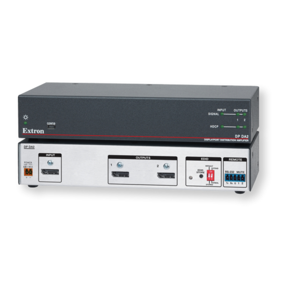
Panel Features This section describes the panel features and connections of the DP DA2. Rear Panel DP DA2 INPUT OUTPUTS EDID REMOTE DEFAULT POWER EXTEND EDID RS-232 MUTE STORE 0.6A MAX NORMAL STORED d e f Figure 2. DP DA2 Rear Panel Power —... -
Page 10: Rear Panel Features
Do not tin the wires. Tinned wire does not hold its shape and comes loose over time. Connect the AC power cord of the power supply unit to a 110 or 220 VAC electrical source. When the unit is receiving power, the front panel LED shows a green light. DP DA2 • Panel Features... -
Page 11: Display Port Connectors
Power for adapters (3.3 V 500 mA) The DP DA2 supports data rates of either 1.62 Gbps (reduced bit rate) or 2.7 Gbps (high bit rate), using either one, two, or four lanes. The DP DA2 supports mini DisplayPort and Dual Mode DisplayPort through the use of the appropriate adapters and cables (not provided). -
Page 12: Edid Minder
EDID is recorded, it overwrites the existing data and is available with DIP switch 1 in the Stored position. NOTE: If the EDID for a display device is corrupted or cannot be read, the DP DA2 will continue to use the currently stored EDID. EDID Minder LED The LED shows the status of the EDID recording process: •... -
Page 13: Dip Switches
2560x1600 @ 60Hz and multi-channel audio. If the DIP switch is in the Extend (up) position, the DP DA2 provides an image with a resolution of up to 3840x1080 @ 60 Hz and 2-ch audio extended over two output displays. -
Page 14: Rs-232 Control
They are labelled Tx, Rx, and G. The Ground (G) is RS-232 MUTE shared with the mute controls. Alternatively, the front panel USB port may be used. Connect the DP DA2 to a control PC, as follows: RS-232 REMOTE DP DA2... -
Page 15: Config Usb Port
Config USB Port Connecting to the USB Port The mini Type B USB port is located on the DP DA2 front panel. It can be used to connect the distribution amplifier to a host computer to update firmware or for configuration using RS-232 captive screw connectors SIS commands. - Page 16 The wizard appears only on the first occasion you connect the DP DA2 to that USB port. The wizard will reappear if you connect the DP DA2 to a different USB port or if you connect a different piece of equipment, requiring a different driver, to the same USB port.
-
Page 17: Signal And Hdcp Leds
Output HDCP LED — lights green when the connected display device is HDCP compliant. NOTE: The HDCP LEDs will not light if the source device does not require HDCP encryption or if the display devices are not HDCP compliant. DP DA2 • Panel Features... -
Page 18: Setup
If necessary, connect the DP DA2 to a control PC using either the rear panel RS-232 captive screw connectors or the front panel USB mini B connector. Power on the DP DA2 and the PC and configure the DP DA2 as required, using SIS commands. -
Page 19: Sis Commands
• Introduction to SIS The DP DA2 accepts SIS commands from a host device such as a computer running the Extron DataViewer utility or other control system. The host device can be connected to the 3-pin captive screw connector on the rear panel or to the config port on the front panel. To connect to the config port, use the optional Extron USB CFG cable (part number 26-654-06). -
Page 20: Symbols Used In This Manual
The last character must not be a minus sign (hyphen). Error Messages E01 — Invalid input channel number (too large) E10 — Invalid command E13 — Invalid value (too large) E14 — Not valid for this configuration DP DA2 • SIS Commands... -
Page 21: Command And Response Table For Sis Commands
The last character must not be a minus sign/hyphen. Other Request part number 60-1221-01 Query firmware version Firmware version (with 2 decimals) Reset ZXXX ...go Upload firmware During upload process Upload When upload is complete DP DA2 • SIS Commands... -
Page 22: Updating Firmware
Updating Firmware Updates to the DP DA2 firmware are released periodically on the Extron website. You can find the version that is currently loaded on your DA using SIS commands. Compare this with the latest release on the Extron website and decide whether to update your firmware. -
Page 23: Downloading Dp Da2 Firmware
Figure 9. Firmware Link on the Download Tab On the next Download Center screen, locate the section for the DP DA2 firmware (Optional) click Release Notes. These notes show the issues that have been addressed by the latest update. If these issues do not affect you, you may decide not to upgrade the firmware. -
Page 24: Loading The Firmware To The Dp Da2
If you have not already done so, download and install the Firmware Loader executable “Downloading and Installing Firmware installer file to your computer (see Loader” on page 16). If necessary, download the latest version of DP DA2 firmware and install it on your computer (see “Downloading DP DA2 Firmware” on page 17). - Page 25 NOTES: • The original factory-installed firmware is permanently available on the DP DA2. If the attempted firmware upload fails for any reason, the switcher reverts to the factory version. • When downloaded from the Extron website, by default the...
- Page 26 Devices section of the Firmware Loader window and the Add Device window closes. If you will be uploading the firmware to multiple DP DA2 units that are connected to your computer, do the following:...
-
Page 27: Resetting Firmware To The Factory Default Version
Use a screwdriver with a fine blade to press the reset button for 10 seconds while powering on the DP DA2. The front panel power LED blinks amber three times, then lights solid amber, and finally blinks amber three more times while the reset occurs. When the reset is complete, it lights solid green. -
Page 28: Reference Information
RSU 126: 6 inch deep, 1U rack shelf kit 60-190-10 RSB 126: 6 inch deep, 1U basic rack shelf 60-604-11 RSU 129: 9.5 inch deep, 1U rack shelf kit 60-190-01 RSB 129: 9.5 inch deep, 1U basic rack shelf 60-604-02 DP DA2 • Reference Information... -
Page 29: Mounting
RSU 129: 9.5 inch deep, 1U rack shelf kit (part number 60-190-01) • RSB 129: 9.5 inch deep, 1U basic rack shelf (part number 60-604-02) To mount the scaler on a rack shelf, follow the instructions provided with the shelf accessories. DP DA2 • Mounting... -
Page 30: Extron Warranty
Extron Electronics makes no further warranties either expressed or implied with respect to the product and its quality, performance, merchantability, or fitness for any particular use. In no event will Extron Electronics be liable for direct, indirect, or consequential damages resulting from any defect in this product even if Extron Electronics has been advised of such damage.
Need help?
Do you have a question about the DP DA2 and is the answer not in the manual?
Questions and answers