Extron electronics DVI DA2 User Manual
Digital visual interface distribution amplifier
Hide thumbs
Also See for DVI DA2:
- User manual (20 pages) ,
- Setup manual (2 pages) ,
- User manual (5 pages)

Related Manuals for Extron electronics DVI DA2


Summary of Contents for Extron electronics DVI DA2
- Page 1 User’s Manual DVI DA2 and DVI DA4 Digital Visual Interface Distribution Amplifier 68-1376-01 Rev. B 08 08...
- Page 2 Safety Instructions • English This symbol is intended to alert the user of important operating and maintenance (servicing) instructions in the literature provided with the equipment. This symbol is intended to alert the user of the presence of uninsulated dangerous voltage within the product’s enclosure that may present a risk of electric shock.
- Page 3 安全须知 • 中文 这个符号提示用户该设备用户手册中 有重要的操作和维护说明。 这个符号警告用户该设备机壳内有暴 露的危险电压,有触电危险。 注意 阅读说明书 • 用 户 使 用 该 设 备 前 必 须 阅 读 并 理 解 所 有 安 全 和 使 用 说 明 。 保存说明书 • 用户应保存安全说明书以备将来使 用。 遵守警告 • 用户应遵守产品和用户指南上的所有安 全和操作说明。...
- Page 5 To install, cable, and power on the DVI DA2 and DVI DA4: Step 1 Installation Install the DVI DA2 or DVI DA4 on a desk, mount it under a desk, or mount it in a rack. Step 2 DVI Cable Connections Connect a DVI cable from the Input connector to the video source device.
- Page 6 Quick Start Guide — DVI DA2 and DA4, cont’d Step 3 Power Cable Connections Check the polarity of the cable. Smooth Connect the 12 VDC power supply to the unit's power receptacle. Connect the 12 VDC power cord to an AC power outlet.
-
Page 7: Table Of Contents
Appendix A • Reference Information Specifications Included Parts Accessories ...A-4 All trademarks mentioned in this manual are the properties of their respective owners. DVI DA2 and DVI DA4 • Table of Contents ... 1-1 ... 1-2 ... 1-3 ... 2-2 ... 2-6 ... - Page 8 Table of Contents, cont’d DVI DA2 and DVI DA4 • Table of Contents...
-
Page 9: Chapter One • Introduction
DVI DA2 and DVI DA4 Chapter One Introduction About this manual About the DVI DA2 and DVI DA4 DVI DA2 and DVI DA4 Features... -
Page 10: About This Manual
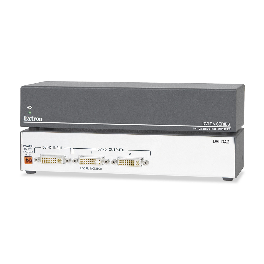
(DAs) have one input and either two (DVI DA2) or four (DVI DA4) outputs. Both distribution amplifiers accept one single link DVI-D input and drive two (DVI DA2) or four (DVI DA4) single link DVI-D output signals. In both models, Output 1, is used for Digital Display Channel (DDC) reference. -
Page 11: Dvi Da2 And Dvi Da4 Features
DVI DA2 and DVI DA4 Features External power supply — The DVI DA2 and DVI DA4 are powered by external 12 VDC power supply (provided with the units). DVI-D input — link DVI-D input, with a resolution range up to 1920 x 1200 or 1080p @ 60 Hz. - Page 12 Introduction, cont’d DVI DA2 and DVI DA4 • Introduction...
-
Page 13: Chapter Two • Installation And Operation
DVI DA2 and DVI DA4 Chapter Two Installation and Operation Installation Overview Mounting the Distribution Amplifier Front Panel Features Rear Panel Features Cable Connections Operation Troubleshooting... -
Page 14: Installation Overview
Circuit overloading — Connect the equipment to the supply circuit and consider the effect that circuit overloading might have on overcurrent protection and supply wiring. Give appropriate consideration to the equipment nameplate ratings when addressing this concern. DVI DA2 and DVI DA4 • Installation and Operation... -
Page 15: Rack Mounting Procedure
4-40 x 3/16" screws to secure the unit on the shelf. Install other unit(s) or false faceplate(s) on the rack shelf. DVI DA2 and DVI DA4 • Installation and Operation ® rack shelf kit 1/2 Rack Width Front False Faceplate (2) 4-40 x 3/16"... -
Page 16: Under-Desk Mounting
Attach the shelf to the rack with the four provided 10-32 x 3.4" screws. Under-desk mounting The DVI DA2 and DVI DA4 can be mounted under furniture using the optional Extron MBU 125 under-desk mounting kit (part # 70-077-01). Under furniture mounting... - Page 17 DVI DA2 and DVI DA4 • Installation and Operation...
-
Page 18: Front Panel Features
Installation and Operation, cont’d Front Panel Features Front panel features LED indicator — On both the DVI DA2 and DVI DA4, the LED indicator illuminates green when the unit is receiving power. DVI DA2 and DVI DA4 • Installation and Operation... -
Page 19: Rear Panel Features
DDC reference. For the input device to provide a signal at the correct resolution and refresh rate, there must be a display device connected to output 1. DVI DA2 and DVI DA4 • Installation and Operation INPUT LOCAL OUTPUT... -
Page 20: Cable Connections
1. DVI DA2 and DVI DA4 • Installation and Operation Although DVI-I connectors are used, these distribution amplifiers are only compatible with single-link DVI-D video signals. -
Page 21: Dvi Connector Pin Assignments
The illustration below shows the pin assignments for the DVI-I male and female connectors. Although DVI-I dual link connectors are used, the DVI DA2 and DVI DA4 are only compatible with single-link DVI-D video signals. DVI-I Dual Link - Female... -
Page 22: Power Connections
Connecting the power supply Connect the AC power cord of the power supply unit to a 110 or 220 VAC electrical source. DVI DA2 and DVI DA4 • Installation and Operation 2-10 Ensure the cable is connected with the correct polarity. -
Page 23: Operation
Connect and power on any other output displays (see page 2-8). Connect and power on the source device (see page 2-8). DVI DA2 and DVI DA4 • Installation and Operation Output 1 (LOCAL OUTPUT) is used as a DDC reference and must be connected to the distribution amplifier before the source device. -
Page 24: Troubleshooting
— A device that is not HDCP compliant may be receiving HDCP-encrypted signals. The DVI DA2 and DVI DA4 are not High-Bandwidth Digital Content Protection (HDCP) compliant. They will only pass HDCP-encrypted signals to the local output device. -
Page 25: Appendix A • Reference Information
DVI DA2 and DVI DA4 A ppendix A Reference Information Specifications Included Parts Accessories... - Page 26 Connectors ... 1 female DVI-I Video Output Numbers/signal type DVI DA2 ... 2 single link DVI-D (or HDMI*): 1 main, 1 Local output is used for DDC communications and hot plug detection DVI DA4 ... 4 single link DVI-D (or HDMI*) Connectors ...
- Page 27 Warranty... 3 years parts and labor All nominal levels are at ±10% Specifications are liable to change without notice DVI DA2 and DVI DA4 • Reference Information Mounting Kit, #70-077-01 (1U high, half rack wide) (4.4 cm H x 22.2 cm W x 7.6 cm D) (Depth excludes connectors.)
- Page 28 RSU 126 (6" deep, 1U rack shelf kit) RSB 126 (6" deep, 1U basic rack shelf) RSU 129 (9.5" deep, 1U rack shelf kit) RSB 129 (9.5" deep, 1U basic rack shelf) DVI DA2 and DVI DA4 • Reference Information Replacement part number 60-886-01...
- Page 29 Extron Electronics warrants this product against defects in materials and workmanship for a period of three years from the date of purchase. In the event of malfunction during the warranty period attributable directly to faulty workmanship and/or materials, Extron Electronics will, at its option, repair or replace said products or components, to whatever extent it shall deem necessary to restore said product to proper operating condition, provided that it is returned within the warranty period, with proof of purchase and description of malfunction to:...
- Page 30 Extron USA - West Extron USA - East Headquarters +800.633.9876 +800.633.9876 Inside USA / Canada Only Inside USA / Canada Only +1.919.863.1794 +1.714.491.1500 +1.919.863.1797 FAX +1.714.491.1517 FAX © 2008 Extron Electronics. All rights reserved. Extron Europe Extron Asia Extron Japan +800.3987.6673 +800.7339.8766 +81.3.3511.7655...
Need help?
Do you have a question about the DVI DA2 and is the answer not in the manual?
Questions and answers