Sign In
Upload
Download
Table of Contents
Contents
Add to my manuals
Delete from my manuals
Share
URL of this page:
HTML Link:
Bookmark this page
Add
Manual will be automatically added to "My Manuals"
Print this page
×
Bookmark added
×
Added to my manuals
Manuals
Brands
AEMC Manuals
Measuring Instruments
670
User manual
AEMC 670 User Manual
Clamp-on meter
Hide thumbs
1
2
Table Of Contents
3
4
5
6
7
8
9
10
11
12
13
14
15
16
17
18
19
20
21
22
23
24
25
26
27
28
29
30
31
32
page
of
32
Go
/
32
Contents
Table of Contents
Bookmarks
Table of Contents
Table of Contents
1 Introduction
International Electrical Symbols
Definition Of Measurement Categories
Receiving Your Shipment
Ordering Information
Accessories/Replacement Parts
2 Product Features
Description
Model 670/675 Control Features
Lcd Display
Button Functions
Hold Button
Correction Of Zero In
DC Measurement
Auto Power Off
Display Button
Min/Max Function (500Ms)
Peak Function (1Ms)
Backlight Button
4 Specifications
Electrical Specifications
Mechanical Specifications
Environmental Specifications
Safety Specifications
Operation
Ac Current Measurement
Ac Voltage And Current
Measurement Simultaneously
DC Current Measurement (675 Only)
Ac Volt Measurement
DC Volt Measurement
Resistance Measurement
Continuity Measurement
Temperature Measurement
Frequency Measurement Using
Voltage Input
Frequency Measurement Using Current Input
5 Maintenance
Warning
Cleaning
Battery Replacement
Repair And Calibration
Technical And Sales Assistance
Limited Warranty
Warranty Repairs
Advertisement
Quick Links
Download this manual
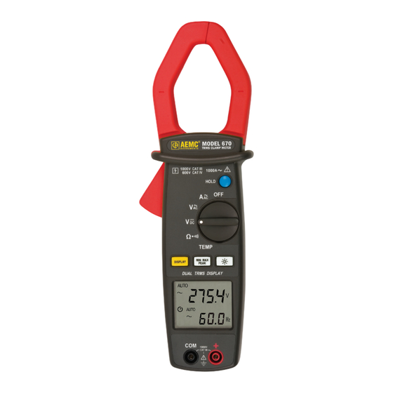
670
CLAMP-ON METER
675
E N G L I S H
User Manual
Table of
Contents
Previous
Page
Next
Page
1
2
3
4
5
Advertisement
Table of Contents
Need help?
Do you have a question about the 670 and is the answer not in the manual?
Ask a question
Questions and answers
Related Manuals for AEMC 670
Measuring Instruments AEMC 675 User Manual
Clamp-on meter (32 pages)
Measuring Instruments AEMC 6550 Quick Start User Manual
(13 pages)
Measuring Instruments AEMC 6550 User Manual
10kv and 15kv megohmmeters (72 pages)
Measuring Instruments AEMC 6470-b User Manual
Digital ground resistance and soil resistivity tester (76 pages)
Measuring Instruments AEMC 6527 User Manual
Megohmmeter (32 pages)
Measuring Instruments AEMC 6608 User Manual
Phase rotation meter (24 pages)
Measuring Instruments AEMC 6250 User Manual
Micro-ohmmeter (64 pages)
Measuring Instruments AEMC 6240 User Manual
Micro-ohmmeter (32 pages)
Measuring Instruments AEMC 6536 User Manual
Megohmmeter (48 pages)
Measuring Instruments AEMC 6526 User Manual
Megohmmeter (48 pages)
Measuring Instruments AEMC 6526 Quick Start Manual
Megohmmeter (17 pages)
Measuring Instruments AEMC 6505 User Manual
Megohmmeter (32 pages)
Measuring Instruments AEMC 607 User Manual
Clamp-on meter (72 pages)
Measuring Instruments AEMC 6422 User Manual
Ground tester (44 pages)
Measuring Instruments AEMC 6424 User Manual
Ground tester (44 pages)
Measuring Instruments AEMC 603 User Manual
Clamp-on meter (44 pages)
This manual is also suitable for:
675
Table of Contents
Print
Rename the bookmark
Delete bookmark?
Delete from my manuals?
Login
Sign In
OR
Sign in with Facebook
Sign in with Google
Upload manual
Upload from disk
Upload from URL


Need help?
Do you have a question about the 670 and is the answer not in the manual?
Questions and answers