
Subscribe to Our Youtube Channel
Related Manuals for AXIOMTEK MPC152-832


Summary of Contents for AXIOMTEK MPC152-832
- Page 1 MPC152-832 All-in-One 15” XGA TFT Fanless Medical Touch ® PanelComputer with Intel Atom D2550 Processor Onboard User’s Manual...
- Page 2 Axiomtek does not make any commitment to update the information in this manual. Axiomtek reserves the right to change or revise this document and/or product at any time without notice. No part of this document may be reproduced, stored in a retrieval system, or transmitted, in any form or by any means, electronic, mechanical, photocopying, recording, or otherwise, without the prior written permission of Axiomtek Co., Ltd.
-
Page 3: Safety Precautions
Most electronic components are sensitive to static electrical charge. Disconnect the power cords from the MPC152-832 Series before making any installation. Be sure both the system and the external devices are turned OFF. Sudden surge of power could ruin sensitive components. Make sure the MPC152-832 Series is properly grounded. -
Page 4: Table Of Contents
Table of Contents Disclaimers ..................... ii Safety Precautions ..................iii Chapter 1 Introduction ..........1 General Description ................1 Specifications ..................2 Dimensions ..................4 I/O Outlets .................... 6 Packing List ..................7 Chapter 2 Hardware and Installation ...... 9 CF card Installation ................ - Page 5 Security Menu ..................38 Save & Exit Menu ................39 Chapter 4 Drivers Installation ......41 System ....................41 Touch Screen ..................41 Embedded O.S................... 43...
- Page 6 This page is intentionally left blank.
-
Page 7: Chapter 1 Introduction
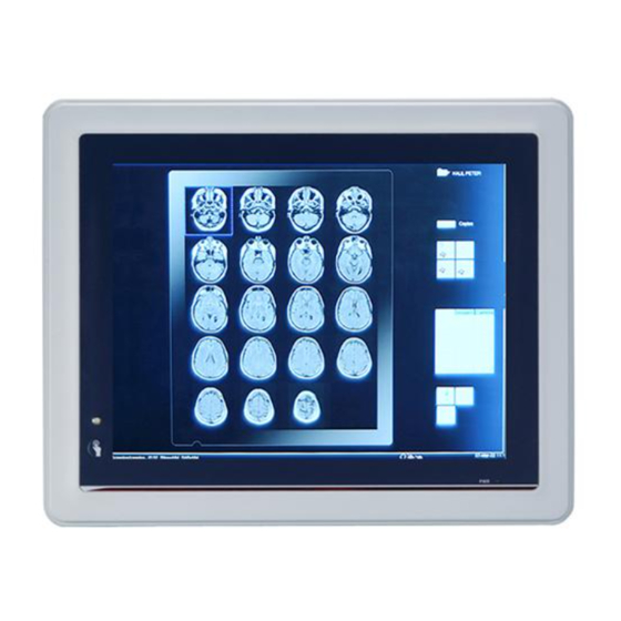
Dimensions I/O Outlets Package List General Description The MPC152-832 is a fan-less and compact-size medical touch panel computer, equipped with ○ a 15” TFT LCD display and low power consumption Intel Atom D2550 1.86GHz processor. ® ®... -
Page 8: Specifications
One PCIe Mini card Storage One slot for CF card One 2.5” SATA HDD Power connector MPC152-832-DC: 10VDC to 30VDC with phoenix power connector MPC152-832-J: External 60W Medical AC Adapter with screw type connector Introduction... - Page 9 — Power Output: 12VDC, Max. 5A — NOTE All specifications and images are subject to change without notice. NOTE The DC power source to be used with MPC152-832 must be galvanically isolated according to IEC60601-1 safety of medical devices! Introduction...
-
Page 10: Dimensions
MPC152-832 User’s Manual Dimensions This diagram shows you dimensions and outlines of the MPC152-832. Introduction... - Page 11 MPC152-832 User’s Manual Introduction...
-
Page 12: I/O Outlets
MPC152-832 User’s Manual I/O Outlets Please refer to the following illustration for I/O locations of the MPC152-832. Function Function POWER SWITCH (ATX) COM 1 (RS-232/422/485) Power Input connector (Screw) Display Port Power Input connector (Phoenix) Ethernet (RJ-45) Dual USB 2.0 ports Dual USB 2.0 ports... -
Page 13: Packing List
Panel Mount Kit x 10 (optional) Phoenix connector x 1 (for MPC152-832-DC) Power Adapter & power cord (for MPC152-832-J) If you can not find the package or any items are missing, please contact Axiomtek distributors immediately. Introduction... - Page 14 MPC152-832 User’s Manual This page is intentionally left blank. Introduction...
-
Page 15: Hardware And Installation
MPC152-832 User’s Manual Chapter 2 Hardware and Installation The MPC152-832 provides rich I/O ports and flexible expansions for you to meet different demand, for example, CF card. The chapter will show you how to install the hardware. It includes: ™... -
Page 16: Cf Card Installation
MPC152-832 User’s Manual CF card Installation ™ The MPC152-832 provides one CF slot for users to install CompactFlash card. Please refer to the following instructions for installation: Step 1 Turn off the system, and unplug the power cord. Step 2 Remove the cover of CF socket. -
Page 17: Jumper And Switch Setting & Com Port Connector
And remove jumper clip from 2 jumper pins to open. The following illustration shows how to set up jumper. Before applying power to MPC152-832, please make sure all of the jumpers and switch are in factory default position. Below you can find a summary table and onboard default settings. -
Page 18: Com1 Configuration(Jp7, Jp8, Jp9)
2.2.1 COM1 Configuration(JP7, JP8, JP9) The COM1~3 are a standard DB-9 connector. Those connectors are equipped with The MPC152-832 has three serial ports. COM1 is RS-232/422/485, while COM2 and COM3 are RS-232. The following table shows you set COM1 port mode:... -
Page 19: Auto Power On (Jp4)
MPC152-832 User’s Manual 2.2.3 Auto Power On (JP4) If JP4 is enabled for power input, the system will be automatically power on without pressing soft power button. If JP4 is disabled for power input, it is necessary to manually press soft power button to power on the system. -
Page 20: Ethernet
MPC152-832 User’s Manual Ethernet The MPC152-832 is equipped with two high performance Plug and Play Ethernet interfaces, full compliant with IEEE 802.3 standard, and can be connected with a RJ-45 LAN connector. Please refer to detailed pin assignment list below:... -
Page 21: Mountings - Panel/Wall/Desktop/Vesa
There are several mounting ways for the MPC152-832, Panel, Wall, Desktop and VESA mountings. 2.4.1 Panel Mounting (Optional) The MPC152-832 is designed for panel mount application. A set of standard mounting kit are bundled with the system package that you can use it to mount the MPC152-832. Step 1 Remove rubbers on panel mount holes. -
Page 22: Wall-Mounting
MPC152-832 User’s Manual 2.4.2 Wall-Mounting The MPC152-832 is designed for Wall mounting application. Please refer to the following steps: Fix wall mount bracket on the back of the unit. 2.4.3 Desktop-Mounting The MPC152-832 is designed for desktop mounting application. Please refer to the following... - Page 23 MPC152-832 User’s Manual Step 2 Assemble the desktop stand to the chassis, and fix the screws. : CAUTION USE RECOMMENDED/SUITABLE MOUNTING APPARATUS TO AVOID RISK OF INJURY. Hardware and Installation...
-
Page 24: Vesa-Arm Mounting
MPC152-832 User’s Manual 2.4.4 VESA-ARM Mounting : CAUTION USE RECOMMENDED/SUITABLE MOUNTING APPARATUS TO AVOID RISK OF INJURY. Step 1 Find out the screws as marked on the back side of chassis. Step 2 Assemble the VESA-ARM to the back side of the chassis, and fix the screws. -
Page 25: Hdd Installation
MPC152-832 User’s Manual HDD Installation The MPC152-832 provides a convenient Hard Disk Drive (HDD) bracket for users to install 2.5” SATA HDD. Please follow the steps: Step 1 Unscrew eight screws to remove the back cover. Hardware and Installation... - Page 26 MPC152-832 User’s Manual Screw the 2.5” HDD to the HDD bracket. Step 2 Step 3 Fix the HDD bracket into the system, and plug the data and power cable to HDD. Installation complete. Hardware and Installation...
-
Page 27: Dram Installation
MPC152-832 User’s Manual DRAM Installation The MPC152-832 provides one 204-pin DDR3 SODIMM socket that support system memory up to 4GB. Please follow steps below to install the memory modules: Step 1 Open the back cover and find out the DIMM socket on main board(SBC87832). - Page 28 MPC152-832 User’s Manual Step 3 Install the memory module into the socket and push it firmly down until it is fully seated. The socket latches are levered upwards and clipped on to the edges of the DIMM. Hardware and Installation...
-
Page 29: Wireless Lan Card Installation
MPC152-832 User’s Manual Wireless LAN Card Installation The MPC152-832 provides one Mini card slot for user to install one wireless LAN card. When installing the wireless LAN card, refer to the following instructions and illustration: Step 1 Open the back cover and find out the mini-card slot on main board. -
Page 30: Power Input (Phoenix Type)
Connect antenna cable to MAIN connector on wireless LAN card. Power Input (Phoenix type) MPC152-832 equips with a phoenix type power connector. It adopts 10VDC to 30VDC. Please follow the signs on power connector to connect DC power source. -
Page 31: Ami Bios Setup Utility
MPC152-832 User’s Manual Chapter 3 AMI BIOS Setup Utility This chapter provides users with detailed description how to set up basic system configuration through the AMIBIOS8 BIOS setup utility. Starting To enter the setup screens, follow the steps below: Turn on the computer and press the <Del> key immediately. -
Page 32: Main Menu
MPC152-832 User’s Manual Main Menu When you first enter the Setup Utility, you will enter the Main setup screen. You can always return to the Main setup screen by selecting the Main tab. There are two Main Setup options. They are described in this section. The Main BIOS Setup screen is shown below. -
Page 33: Advanced Menu
MPC152-832 User’s Manual Advanced Menu Launch PXE OpROM Use this item to enable or disable the boot ROM function of the onboard LAN chip when the system boots up. Launch Storage OpROM This item can enable or disable boot option for legacy mass storage devices with option ROM. - Page 34 MPC152-832 User’s Manual ACPI Settings You can use this screen to select options for the ACPI Configuration, and change the value of the selected option. A description of the selected item appears on the right side of the screen.
- Page 35 MPC152-832 User’s Manual CPU Configuration This screen shows the CPU Configuration, and you can change the value of the selected option. Hyper-Threading Use this item to enable or disable Hyper-Threading Technology, which makes a single physical processor perform multi-tasking function as two logical ones.
- Page 36 MPC152-832 User’s Manual IDE Configuration SATA Controller(s) The optional settings are: [Disabled]; [Enabled]. Configure SATA as The optional settings are: [IDE]; [AHCI]. AMI BIOS Setup Utility...
- Page 37 MPC152-832 User’s Manual USB Configuration You can use this screen to select options for the USB Configuration, and change the value of the selected option. A description of the selected item appears on the right side of the screen.
- Page 38 MPC152-832 User’s Manual NCT6627UD Super IO Configuration You can use this screen to select options for the Super IO Configuration, and change the value of the selected option. A description of the selected item appears on the right side of the...
- Page 39 MPC152-832 User’s Manual PC Health Status This screen shows the Hardware Health Configuration, and a description of the selected item appears on the right side of the screen. AMI BIOS Setup Utility...
-
Page 40: Chipset Menu
MPC152-832 User’s Manual Chipset Menu The Chipset menu allows users to change the advanced chipset settings. You can select any of the items in the left frame of the screen to go to the sub menus: ► Host Bridge Host Bridge For items marked with “”, please press <Enter> for more options. - Page 41 MPC152-832 User’s Manual Memory Frequency and Timing This item is for memory frequency and timing settings. Press <Enter> to go to the sub menu. AMI BIOS Setup Utility...
- Page 42 MPC152-832 User’s Manual Intel IGD Configuration You can use this screen to select options for the Intel IGD Configuration, and change the value of the selected option. A description of the selected item appears on the right side of the screen.
-
Page 43: Boot Menu
MPC152-832 User’s Manual Boot Menu The Boot menu allows users to change boot options of the system. Boot Settings Configuration Setup Prompt Timeout Use this item to set number of seconds to wait for setup activation key. Bootup NumLock State Use this item to select the power-on state for the NumLock.. -
Page 44: Security Menu
MPC152-832 User’s Manual Security Menu The Security menu allows users to change the security settings for the system. Administrator Password This item indicates whether an administrator password has been set. If the password has been installed, Installed displays. If not, Not Installed displays. -
Page 45: Save & Exit Menu
MPC152-832 User’s Manual Save & Exit Menu The Save & Exit menu allows users to load your system configuration with optimal or fail-safe default values. Save Changes and Exit When you have completed the system configuration changes, select this option to leave Setup and reboot the computer so the new system configuration parameters can take effect. - Page 46 MPC152-832 User’s Manual Discard Changes Select this option to quit Setup without making any permanent changes to the system configuration. Select Discard Changes from the Save & Exit menu and press <Enter>. Select Yes to discard changes. Restore Defaults It automatically sets all Setup options to a complete set of default settings when you select this option.
-
Page 47: Chapter 4 Drivers Installation
Chapter 4 Drivers Installation System MPC152-832 supports Windows 7 32-bit, WES and WES 7 32-bit. To facilitate the installation of system driver, please carefully read the instructions in this chapter before start installing. Insert Driver CD and select the “\Drivers”. - Page 48 Driver Installation- Windows 7 The MPC152-832 provides a touch screen driver that users can install it under the operating system Winodrws 7. To facilitate installation of the touch screen driver, you should read the instructions in this chapter carefully before you attempt installation.
-
Page 49: Embedded O.s
WIN 7. NOTE: For the better system performance, please close the Windows AERO or change to Windows Basic mode. Embedded O.S. The MPC152-832 provides the Windows 7 Embedded. The O.S. is supported devices which are listed below. WES/WES 7 Here are supported onboard devices: ... - Page 50 MPC152-832 User’s Manual PenMount Touch screen Before you can use and calibrate it, here is what you should do: Set up Penmount touch device driver by executing C:\Penmount\ Windows 2000-XP V5.0\setup.exe. When the installation is finished, an icon “PM” appears on the Taskbar.
Need help?
Do you have a question about the MPC152-832 and is the answer not in the manual?
Questions and answers