
Subscribe to Our Youtube Channel
Related Manuals for AXIOMTEK MIRU130


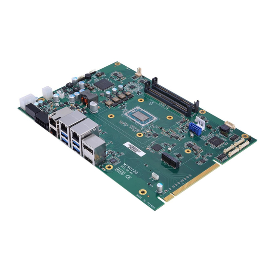
Summary of Contents for AXIOMTEK MIRU130
- Page 1 MIRU130 ® Machine Vision SBC with AMD RYZEN Embedded V1605B/V1807B User’s Manual...
-
Page 2: Disclaimers
Axiomtek does not make any commitment to update the information in this manual. Axiomtek reserves the right to change or revise this document and/or product at any time without notice. No part of this document may be reproduced, stored in a retrieval system, or transmitted, in any form or by any means, electronic, mechanical, photocopying, recording, or otherwise, without the prior written permission of Axiomtek Co., Ltd. -
Page 3: Esd Precautions
It discharges static electricity from your body. Wear a wrist-grounding strap, available from most electronic component stores, when handling boards and components. Trademarks Acknowledgments Axiomtek is a trademark of Axiomtek Co., Ltd. ® ® Intel and Celeron are trademarks of Intel Corporation. -
Page 4: Table Of Contents
Table of Contents Disclaimers ..................... ii ESD Precautions ................... iii Chapter 1 Introduction ..........1 Features ....................2 Specifications ..................2 Utilities ....................3 Chapter 2 Board and Pin Assignments ....5 Board Dimensions and Fixing Holes ..........5 Board Layout ..................7 Switch Settings ................... - Page 5 3.1.2 Isolated Digital Output ................26 3.1.3 Isolated Trigger Input and Auto Measurement Input ......... 26 3.1.4 Isolated Trigger Output ................27 3.1.5 Isolated Encoder Input ................27 Chapter 4 Operating ..........29 Operating ................... 29 4.1.1 Encoder function ..................29 4.1.2 Trigger Input/Output ..................
- Page 6 This page is intentionally left blank.
-
Page 7: Chapter 1 Introduction
I/O functions for interactive applications and various embedded computing solutions. The MIRU130 has two 260-pin unbuffered SO-DIMM sockets for DDR4 2400/3200MHz memory with maximum capacity up to 16GB. There are two Gigabit/Fast Ethernet ports, two Gigabit PoE-PSE ports, one SATA port with transfer rate up to 6Gb/s, four USB 3.1 Gen 2 super speed compliant, two isolated digital-in, and two isolated digital-out that can achieve the best stability and reliability for industrial applications. -
Page 8: Features
Machine Vision MIRU130 Board Features ® RYZEN quad core V1807B (3.35GHz) and V1605B (2.0GHz) 2 DDR4 SO-DIMM support up to 16GB memory capacity 4 USB 3.1 Gen 2 ports 4 COM ports 2 GbE LAN ... -
Page 9: Utilities
Machine Vision MIRU130 Board Watchdog Timer 1~255 seconds or minutes; up to 255 levels. Ethernet Two LAN ports with Realtek RTL8111G support 1000/100/10Mbps Gigabit/Fast Ethernet with Wake-on-LAN and PXE Boot ROM. Two PoE-PSE by Realtek RTL8111G support 1000/100/10Mbps Gigabit/Fast Ethernet with 30W power which is compliant with IEEE802.3at standard. - Page 10 Machine Vision MIRU130 Board This page is intentionally left blank. Introduction...
-
Page 11: Board And Pin Assignments
Machine Vision MIRU130 Board Chapter 2 Board and Pin Assignments Board Dimensions and Fixing Holes Top View Board and Pin Assignments... - Page 12 Machine Vision MIRU130 Board Bottom View Side View Board and Pin Assignments...
-
Page 13: Board Layout
Machine Vision MIRU130 Board Board Layout Top View Board and Pin Assignments... - Page 14 Machine Vision MIRU130 Board Bottom View Board and Pin Assignments...
-
Page 15: Switch Settings
Machine Vision MIRU130 Board Switch Settings Properly configure switch settings on the MIRU130 to meet your application purpose. Below you can find a summary table of all switches and onboard default settings. Once the default switch setting needs to be changed, please do it under power-off condition. -
Page 16: Auto Power On And Restore Bios Optimal Defaults (Sw1)
Machine Vision MIRU130 Board 2.3.1 Auto Power On and Restore BIOS Optimal Defaults (SW1) If dip1 of SW1 (SW1-1) is set to ON position, the system will be automatically power on without pressing soft power button. If it is set to OFF position, it is necessary to manually press soft power button to power on the system. -
Page 17: Connectors
Machine Vision MIRU130 Board Connectors Signals go to other parts of the system through connectors. Loose or improper connection might cause problems, please make sure all connectors are properly and firmly connected. Here is a summary table of connectors on the hardware. -
Page 18: Tpm Wafer Connector (Cn1)
Machine Vision MIRU130 Board 2.4.1 TPM Wafer Connector (CN1) The CN1 is an 8-pin (pitch=1.25mm) wafer connector which is compliant with Molex 510210800 for TPM module via SPI interface. AX93515 is TPM module which is suggested to use. Signal SPI_TPM_MISO... -
Page 19: Com Wafer Connectors (Cn3, Cn4, Cn7 And Cn8)
Machine Vision MIRU130 Board 2.4.3 COM Wafer Connectors (CN3, CN4, CN7 and CN8) These are four 9-pin (pitch=1.25mm) COM wafer connectors which are compliant with Molex 53047-0910. The pin assignments of RS-232/RS-422/RS-485 are listed in table below. If you need COM1 to support RS-422 or RS-485 communication mode, please refer to BIOS setting in section 6.4. -
Page 20: Front Panel Connector (Cn10)
Machine Vision MIRU130 Board 2.4.4 Front Panel Connector (CN10) This is a 2x6-pin header (pitch=2.0mm) for front panel interface. Signal Signal Buzzer- Buzzer+ PWR_PSON PWRLED- PWRLED+ PWRSW- PWRSW+ HW RST- HW RST+ HDDLED- HDDLED+ Internal Buzzer Pin 1(-) and 2(+) connect the internal buzzer cable. -
Page 21: 2230 Key E Connector (Cn11)
Machine Vision MIRU130 Board 2.4.5 M.2 2230 Key E Connector (CN11) The CN11 is a M.2 2230 Key E connector. It is suggested to install the M.2 wireless module via PCIe x1 with 22mm width and 30mm length. Signal Signal +3.3V_SBY... -
Page 22: Led Lighting Control Wafer Connector (Cn12)
Machine Vision MIRU130 Board 2.4.6 LED Lighting Control Wafer Connector (CN12) The CN12 is a 4-pin (pitch=2.0mm) wafer connector for two channel LED lighting control interface. Each channel can be set for 100mA/250mA/350mA/500mA output by switch (see Section 2.3.2), supporting dimming control. -
Page 23: Poe-Pse Port (Cn15)
Machine Vision MIRU130 Board 2.4.9 PoE-PSE Port (CN15) The board has two RJ-45 PoE-PSE ports which is compliant with IEEE802.3at standard. 1000 100/10 Description Base-T Base-T BI_DA+ Bidirectional or Transmit Data+ BI_DA- Bidirectional or Transmit Data- BI_DB+ Bidirectional or Receive Data+ BI_DC+ N.C. -
Page 24: Displayport And Hdmi Connector (Cn18)
Machine Vision MIRU130 Board USB: Signal Signal USB_VCC (+5V ) USB_VCC (+5V ) USB #0_D- USB #1_D- USB #0_D+ USB #1_D+ SSRX0- SSRX1- SSRX0+ SSRX1+ SSTX0- SSTX1- SSTX0+ SSTX1+ 2.4.11 DisplayPort and HDMI Connector (CN18) The CN18 is a double-deck connector with DisplayPort (upper) and HDMI (lower) port. -
Page 25: Digital I/O Connector (Cn19)
Machine Vision MIRU130 Board 2.4.12 Digital I/O Connector (CN19) The CN19 is a 12-pin connector for digital I/O interface, including two isolated digital-in, two isolated digital-out, two isolated trigger-in and two isolated trigger-out for camera. Option female connector: 53403060B00E CN-TB 2x6 P=3.5 180D 0159-0112 DINKLE... -
Page 26: Sata Connector (Sata1)
Machine Vision MIRU130 Board 2.4.15 SATA Connector (SATA1) This Serial Advanced Technology Attachment (Serial ATA or SATA) connector is for high-speed SATA interface. It is a computer bus interface for connecting to devices such as hard disk drive. Signal SATA_TXP0... -
Page 27: Key B Connector (Scn1)
Machine Vision MIRU130 Board 2.4.17 M.2 Key B Connector (SCN1) The SCN1 is a M.2 Key B connector. It is suggested to install the M.2 storage module via SATA with 22mm width and 42mm or 80mm length or the M.2 cellular module via USB 2.0 or USB3.0 with 30mm width and 42mm length. -
Page 28: Pci-Express X16 Golden Finger (Gf1)
Machine Vision MIRU130 Board 2.4.18 PCI-Express x16 Golden Finger (GF1) The GF1 is a PCIe x16 golden finger to support PCIex8. The AX96809 riser card is suggested to use to have PCIex16 slot. Signal Signal PRSNT1# +12V +12V +12V +12V... - Page 29 Machine Vision MIRU130 Board HSOP_6 HSON_6 HSIP_6 HSIN_6 HSOP_7 HSON_7 HSIP_7 HSIN_7 PRSNT2#2 Board and Pin Assignments...
-
Page 30: Ddr4 So-Dimm Set Up (Dimm1, Dimm2)
Machine Vision MIRU130 Board 2.4.19 DDR4 SO-DIMM Set Up (DIMM1, DIMM2) Install the memory module(s) into DIMM1 or DIMM2 carefully as indicated in image below. First, follow arrow 1, insert memory module at approximately 15 degree angle into the socket. Then push module in the direction of arrow 2 until it completely fits into DIMM1 or DIMM2. -
Page 31: Chapter 3 I/O Connection
Machine Vision MIRU130 Board Chapter 3 I/O Connection I/O Connection Refer to this section to connect any cables between the MIRU130 and device. Each of the following I/O figures illustrates their respective connection on the MIRU130. 3.1.1 Isolated Digital Input The following figure shows how to connect between external input source and the MIRU130. -
Page 32: Isolated Digital Output
3.1.2 Isolated Digital Output The following figure shows how to connect between an output channel and the MIRU130. If an external voltage 5~30VDC is applied to an isolated output channel, the current will flow from the external voltage source to the board. Please note that the current through each DO channel should not exceed 200mA. -
Page 33: Isolated Trigger Output
Each of the isolated digital input channels accepts 0~30VDC with sink type. 3.1.4 Isolated Trigger Output The following figure shows how to connect between an output channel and the MIRU130. The board provides voltage 12VDC for an isolated output channel. 3.1.5 Isolated Encoder Input The following figure shows how to connect between an input channel and the MIRU130. - Page 34 Machine Vision MIRU130 Board 5V Voltage Type: I/O Connection...
-
Page 35: Chapter 4 Operating
A is either 90° phase leading or lagging behind Phase B. The MIRU130 is able to count square-wave pulses of Phase A and Phase B, and then determine rotating direction of motor movement by comparing the phase relationship between Phase A and B: ... -
Page 36: Trigger Input/Output
Encoder Check Pointer CH0~2. Note: One trigger source can be set to activate multiple trigger outputs. Delay time function The user can set the delay time that the MIRU130 waits before it sends a trigger output. Duration time The user can adjust pulse width for the output signal. -
Page 37: Led Lighting Control
4.1.4 Interrupt This function can send an interrupt signal to the host PC. The user can select two conditions from the list below for the MIRU130 to generate an interrupt signal: Digital Input Trigger Input Encoder Phase Z Encoder Check Pointer... - Page 38 Machine Vision MIRU130 Board This page is intentionally left blank. Operating...
-
Page 39: Chapter 5 Hardware Description
CPU from damages. BIOS The MIRU130 uses AMI Plug and Play BIOS with a single 64Mbit SPI Flash. System Memory The MIRU130 supports two 260-pin DDR4 SO-DIMM sockets. The memory module comes in sizes of 2GB, 4GB and 8GB. -
Page 40: I/O Port Address Map
Machine Vision MIRU130 Board I/O Port Address Map Hardware Description... -
Page 41: Interrupt Controller (Irq) Map
Machine Vision MIRU130 Board Interrupt Controller (IRQ) Map The interrupt controller (IRQ) mapping list is shown as follows: Hardware Description... - Page 42 Machine Vision MIRU130 Board Hardware Description...
- Page 43 Machine Vision MIRU130 Board Hardware Description...
- Page 44 Machine Vision MIRU130 Board Hardware Description...
- Page 45 Machine Vision MIRU130 Board Hardware Description...
-
Page 46: Memory Map
Machine Vision MIRU130 Board Memory Map The memory mapping list is shown as follows: Hardware Description... -
Page 47: Ami Bios Setup Utility
Machine Vision MIRU130 Board Chapter 6 AMI BIOS Setup Utility The AMI UEFI BIOS provides users with a built-in setup program to modify basic system configuration. All configured parameters are stored in a flash chip to save the setup information whenever the power is turned off. - Page 48 Machine Vision MIRU130 Board Hot Keys Description Left/Right The Left and Right <Arrow> keys allow you to select a setup screen. The Up and Down <Arrow> keys allow you to select a setup screen or Up/Down sub-screen. The Plus and Minus <Arrow> keys allow you to change the field value of a +...
-
Page 49: Main Menu
Machine Vision MIRU130 Board Main Menu When you first enter the setup utility, you will enter the Main setup screen. You can always return to the Main setup screen by selecting the Main tab. System Time/Date can be set up as described below. -
Page 50: Advanced Menu
Machine Vision MIRU130 Board Advanced Menu The Advanced menu also allows users to set configuration of the CPU and other system devices. You can select any of the items in the left frame of the screen to go to the sub menus: ►... - Page 51 Machine Vision MIRU130 Board IT8786 Super IO Configuration You can use this screen to select options for serial port configuration, and change the value of the selected option. A description of the selected item appears on the right side of the screen.
- Page 52 Machine Vision MIRU130 Board Serial Port 1 Configuration Serial Port Enable or disable serial port 1. The optimal setting for base I/O address is 3F8h and for interrupt request address is IRQ4. COM Port Type Use this item to set RS-232/422/485 communication mode.
- Page 53 Machine Vision MIRU130 Board Serial Port 2~4 Configuration Serial Port Enable or disable serial port 2. The optimal setting for base I/O address is 2F8h and for interrupt request address is IRQ3. Enable or disable serial port 3. The optimal setting for base I/O address is 3E8h and for interrupt request address is IRQ11.
- Page 54 Machine Vision MIRU130 Board Hardware Monitor This screen monitors hardware health status. This screen displays the temperature of system and CPU, fan speed in RPM and system voltages. Smart Fan Function Use this item to set Smart Fan function: CPU Fan Setting and System Fan Setting.
- Page 55 Machine Vision MIRU130 Board CPU/System Fan Setting Smart Fan 1/2 Mode The smart fan 1/2 configuration provides two modes: Software and Automatic Mode to control fan speed. In Automatic Mode, the fan speed is controlled by the following parameters: Temperature input selection: Choose System Temperature1, System Temperature2 or CPU Temperature.
- Page 56 Machine Vision MIRU130 Board In Software Mode, the fan speed is controlled manually by PWM value and its range is from 0 to 255 (see image below). ACPI Settings ACPI Sleep State Select the ACPI (Advanced Configuration and Power Interface) sleep state. Configuration options are Suspend Disabled and S3 (Suspend to RAM).
- Page 57 Machine Vision MIRU130 Board Trusted Computing You can use this screen for TPM (Trusted Platform Module) configuration. It also shows current TPM status information. Security Device Support Enable or disable BIOS support for security device. AMI BIOS Setup Utility...
- Page 58 Machine Vision MIRU130 Board CPU Configuration This screen shows the CPU Configuration. SVM Mode Enable or disable SVM (Secure Virtual Machine) mode. Once enabled, you will be able to install a virtual machine on your system. Core Performance Boost If enabled, the CPU can be boosted up to its maximum clock speed when needed.
- Page 59 Machine Vision MIRU130 Board SATA Configuration During system boot up, BIOS automatically detects the presence of SATA devices. In the SATA Configuration menu, you can see the hardware currently installed in SATA ports. USB Configuration USB Devices Display all detected USB devices.
- Page 60 Machine Vision MIRU130 Board Serial Port Console Redirection You can use this screen to select options for Serial Port Console Redirection, and change the value of the selected option. A description of the selected item appears on the right side of the screen.
- Page 61 Machine Vision MIRU130 Board Console Redirection Settings AMI BIOS Setup Utility...
-
Page 62: Chipset Menu
Machine Vision MIRU130 Board Chipset Menu The Chipset menu allows users to change the advanced chipset settings. You can select any of the items in the left frame of the screen to go to the sub menus: ► North Bridge ►... - Page 63 Machine Vision MIRU130 Board North Bridge This screen displays system memory information. And it also allows users to configure parameters of North Bridge chipset. Graphics Configuration Open sub menu for parameters related to graphics configuration. AMI BIOS Setup Utility...
- Page 64 Machine Vision MIRU130 Board Primary Video Adaptor Select Internal (CN18, see section 2.4.11) or External (the graphic card on GF1, see section 2.4.18) Graphics as primary display. IGD UMA Frame Size Set memory frame size for graphic. AMI BIOS Setup Utility...
- Page 65 Machine Vision MIRU130 Board South Bridge This screen shows the AMD Reference Code Version information. AMI BIOS Setup Utility...
-
Page 66: Security Menu
Machine Vision MIRU130 Board Security Menu The Security menu allows users to change the security settings for the system. Administrator Password. Set administrator password. User Password Set user password. AMI BIOS Setup Utility... -
Page 67: Boot Menu
Machine Vision MIRU130 Board Boot Menu The Boot menu allows users to change boot options of the system. Setup Prompt Timeout Number of seconds to wait for setup activation key. 65535(0xFFFF) means indefinite waiting. Bootup NumLock State Use this item to select the power-on state for the keyboard NumLock. - Page 68 Machine Vision MIRU130 Board Launch PXE OpROM policy Control the execution of UEFI PXE OpROM. When enabled, you may select which LAN device will enable PXE OpROM policy. Boot Option Priorities [Boot Option #1, …] These are settings for boot priority. Specify the boot device priority sequence from the available devices.
-
Page 69: Save & Exit Menu
Machine Vision MIRU130 Board Save & Exit Menu The Save & Exit menu allows users to load your system configuration with optimal or fail-safe default values. Save Changes and Exit When you have completed the system configuration changes, select this option to leave Setup and return to Main Menu. - Page 70 Machine Vision MIRU130 Board Discard Changes Select this option to quit Setup without making any permanent changes to the system configuration. Select Discard Changes from the Save & Exit menu and press <Enter>. Select Yes to discard changes. ...
-
Page 71: Appendix A Watchdog Timer
Machine Vision MIRU130 Board Appendix A Watchdog Timer A.1 About Watchdog Timer Software stability is major issue in most application. Some embedded systems are not watched by operator for 24 hours. It is usually too slow to wait for someone to reboot when computer hangs. -
Page 72: A.3 Sample Program
Machine Vision MIRU130 Board A.3 Sample Program //************************************************************** //** //** Copyright(C) 2018, Axiomtek co., Ltd //** //** All Rights Reserved. //** //************************************************************** #include <pc.h> #include <stdio.h> #define SIO_Index_Port 0x2E #define SIO_Data_Port 0x2F #define SIO_Enter_Configuration_Mode 0x01 #define SIO_Entry_key 0x55 #define SIO_LDN_SEL_REGISTER... - Page 73 Machine Vision MIRU130 Board // Select count type for minute type or second type to execute WDT timer // by below method. outportw(SIO_Index_Port,SIO_Offset_Countdown_Type); if(CountdownType == 1) outportw(SIO_Data_Port,SIO_Countdown_Type_Second); else if(CountdownType == 2) outportw(SIO_Data_Port,SIO_Countdown_Type_Minute); // Set WDT Timer outportw(SIO_Index_Port,SIO_Offset_Countdown_Timer); outportw(SIO_Data_Port,WDTtimer); // Exit Configuration Mode outportw(SIO_Index_Port,SIO_Exit_Configuration_Mode);...
Need help?
Do you have a question about the MIRU130 and is the answer not in the manual?
Questions and answers