Advertisement
Quick Links
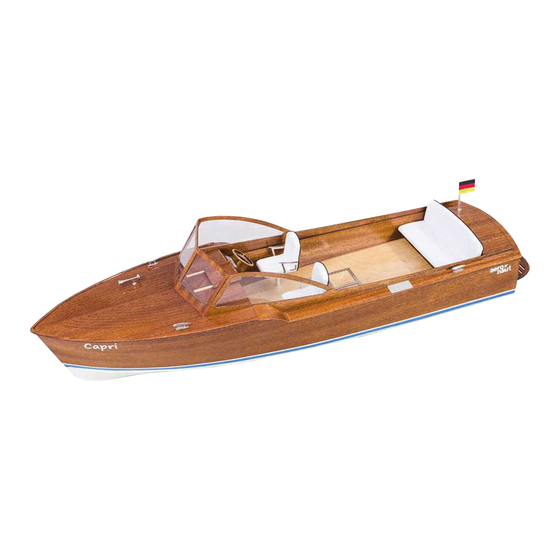
Capri
Introduction:
The model should be assembled following the sequence of the stages of construction described in these instructions.
The laser-cut components are individually numbered. The manufacturing method leaves small tabs on some parts
which have to be cut away using a thin-bladed modelling knife. The dark edges of the laser-cut parts should also be
rubbed off using abrasive paper in order to obtain sound glued joints. Check that all components fit accurately before
reaching for the glue, and carry out any minor trimming required. Allow all glued joints to dry out fully before starting
the next stage of construction. We recommend a fast-setting white glue for all joints. If water-soluble glue is used,
corrections are possible simply by moistening the appropriate area, even after the joint has dried. Once painted over,
the glue becomes waterproof in any case. Please take care to prevent adhesive running onto the untreated
mahogany parts and any external surfaces which will be visible on the finished model, as the glue will show up
through the final painted finish. We recommend that you apply a thin coat of sanding sealer (Order No. 7666/02) to
the mahogany components before gluing, followed by rubbing down with 320-grit abrasive paper. The whole of the
boat - inside and out - must be given several coats of clear waterproof boat lacquer before it is placed in the water, as
this seals the wood and the glued joints. If you have to glue parts to areas which have already been lacquered, use
two-pack adhesive for those joints.
We recommend our aero-pick
modelling pins, Order No. 7855/02, for
holding parts together during
construction.
10
9
0
Order no. 3083/00
11
6
7
8
Lay the Depron jig 0 on a flat surface, or fix it to a flat surface using double-sided
1
adhesive tape.
Insert all the frames 1 - 9 in the slots in the Depron jig. Chamfer the front and top of the
keel 10 at an angle of 30° on both sides, to provide a flat gluing surface for the hull
sides and bottom panels.
Fit the forward keel 10 in the central notches of frames 5 - 9. Insert the two fore-and-
aft bearers 11 in frames 1 - 6.
Power system:
Race 650 electric motor
2-blade boat propeller, 35 mm Order No. 7165/61
Multi 25 speed controller
LiPo (2 - 3S) or NiMH (7-cell) battery
3
4
5
11
Order No. 7124/18
Order No. 7019/71
1
2
Advertisement

Subscribe to Our Youtube Channel
Related Manuals for Aeronaut Capri


Summary of Contents for Aeronaut Capri
- Page 1 Capri Order no. 3083/00 Power system: Race 650 electric motor Order No. 7124/18 2-blade boat propeller, 35 mm Order No. 7165/61 Multi 25 speed controller Order No. 7019/71 LiPo (2 - 3S) or NiMH (7-cell) battery Introduction: The model should be assembled following the sequence of the stages of construction described in these instructions.
- Page 2 Press all the frames down onto the sub- surface in order to align the framework accurately. Apply glue to all the corner joints between the components. Glue former 12 to the rear face of frame 1. To avoid unsightly glue patches, apply a thin coat of sanding sealer to the mahogany face of the hull side panels 13.
- Page 3 Fit the bow end of the hull sides 13 against the keel 10, then lower them steadily, slotting them into the tab notches of the frames as you go. Press the hull sides fully against the keel 10 at the bow, and ensure that they overlap the stern frame 1.
- Page 4 Lay the joined bottom panels 14 on the hull framework. Caution: Don't glue them at this stage! From frame 1 to 6 the bottom panels 14 fit between the hull sides 13, but from frame 6 to frame 9 they rest on the edge of the hull sides 13.
- Page 5 Assemble the boatstand from parts 16 - 18. Sand down the wide face of the triangular rails 19 at the front to reduce their thickness, then glue them to the hull bottom panels 14 and the edge of the hull sides 13. Break off the jig tabs from the keel and frames, and sand off any rough edges.
- Page 6 Fit the rudder bush 26 through the hole in the hull bottom; it should project on the underside of the hull by 3 mm. Fit the bush supports 28 and 29, and glue the bush to the hull and the supports. Glue the keel wedge 30 between the stern tube 21 and the hull bottom panels Glue the stringers 31 + 32 in the...
- Page 7 Insert the cabin sides 33 in the notches in the frames, sliding the sides back as far as they will go until they engage in the notches in frame 1 (see arrow). Glue the stringers 34, 34.1, 35 + 36 in place as shown.
- Page 8 43.1 Glue the frame 43.1 to the frame 43, then glue this assembly between the cabin sides 33 at the marked point. Glue the after deck 40 in place, followed by the side deck panels 39. The curved fairings 44 are formed in a press jig consisting of the 2 x 10 mm parts S1.
- Page 9 Insert the front cockpit wall 48 in the cockpit floor, then engage the front end of the two cockpit sides 47 in the slots in the cockpit floor 46. Place this assembly in the hull and slide it forward until it rests against the frame.
- Page 10 Glue the door 53 and the brackets 54 to the front cockpit wall, then glue the instrument panel backplate 55 to the brackets 54. Glue the foam padding 61 to the seat, and Assemble the seat jig from parts S3 + S4. cut off the excess flush with the edges.
- Page 11 Glue the artificial leather panel 69 to the back of the seat. Bend the left and right armrests 70 to shape and glue them to the seat as shown. Glue the pedestal 57 to the underside of the seat. Repeat the procedure with the second individual seat.
- Page 12 Glue the tube 60 in the hole in part 55; it should project at the front by about 8 mm. Assemble the steering wheel from parts 66 - 69, and glue the nickel-silver boss to the front to finish it off. Bend the nickel-silver rod 79 to follow the shape of the bathing platform 70, and glue it to the edge of the platform;...
- Page 13 Glue the fittings and the remaining etched parts 74 to the boat. Glue the forward hatch cover 71 to the etched nickel-silver rails. Engine 60 PR ESS URE X 100 RPM 60 80 Petrol Pressure Engine 60 PR ESS URE X 100 RPM 60 80 Petrol...
- Page 14 The glazing panels are laser-cut and are an accurate fit in the window openings. Do not remove the small lugs left by the laser cutter, and do not remove the protective film on both sides of the panels. Press the glazing panels into the appropriate openings; the small lugs will hold them in place.
- Page 15 No. Description Material Quant. Size Part Sheet 0 Jig Depron 1 Die-cut 1 Frame Plywood 1 3 mm Laser-cut 2 Frame Plywood 1 3 mm Laser-cut 3 Frame Plywood 1 3 mm Laser-cut 4 Frame Plywood 1 3 mm Laser-cut 5 Frame Plywood 1 3 mm...
- Page 16 No. Description Material Quant. Size Part Sheet 59 Bench seat back Plywood 1 3 mm Laser-cut 60 Steering column Brass tube 1 3/4 Ø x 20 mm Oversize 61 Individual seat padding Foam 2 5 mm Laser-cut 62 Individual seat covering Artificial leather Laser-cut 63 Individual seat armrest...
Need help?
Do you have a question about the Capri and is the answer not in the manual?
Questions and answers