Advertisement
Quick Links
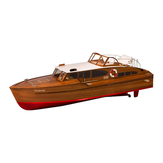
Victoria
Introduction:
The model should be assembled following the sequence of the stages of construction described in these instructions.
The laser-cut components are individually numbered. The manufacturing method leaves small tabs on some parts which have to
be cut away using a thin-bladed modelling knife. The dark edges of the laser-cut parts should also be rubbed off using abrasive
paper in order to obtain sound glued joints. Check that all components fit accurately before reaching for the glue, and carry out
any minor trimming required. Allow all glued joints to dry out fully before starting the next stage of construction. We recommend a
fast-setting waterproof white glue for all joints involving the wooden structure. Water-based glue allows you to make corrections
even when it is hard by moistening the appropriate area; the final coats of paint or lacquer render the joints waterproof. Take care
to prevent adhesive running onto the untreated mahogany parts and any external surfaces which will be visible on the finished
model, as the glue will show up through the final painted finish. We recommend that you apply a coat of sanding sealer (Order
No. 7666/02) to the mahogany components before gluing, and rub down lightly with 320-grit abrasive paper. The whole of the
boat - inside and out - must be given several coats of clear water-resistant boat lacquer before the model is placed in the water,
as this waterproofs the wood and the glued joints. If you have to glue parts to areas which have already been lacquered, use two-
pack adhesive for those joints.
We recommend our aero-pick
modelling pins, Order No. 7855/02, for
use throughout construction
10
9
0
aero-naut Modellbau GmbH & Co.KG, Stuttgarter Str. 18, D-72766 Reutlingen
Bestell-Nr. 3082/00
11
6
7
8
Lay the Depron jig 0 on a flat surface, or fix it to a flat board using double-sided adhesive
1
tape.
Insert all the frames 1 - 9 in the slots in the Depron jig. Sand the front and top of the keel
10 to a 30° bevel on both sides, so that the side and bottom panels rest squarely on them.
Insert the keel 10 in frames 5 - 9, and slot the two fore-and-aft girders 11 in frames 1 - 6.
Power system:
Race 650 electric motor
2-blade boat propeller, 35 mm Ø
Multi 25 speed controller Order No. 7019/71
2-3 LiPo or 7 NiMH cells
4
5
11
Order No. 7124/18
Order No. 7165/61
1
2
3
Advertisement

Related Manuals for Aeronaut Victoria


Summary of Contents for Aeronaut Victoria
- Page 1 Victoria Bestell-Nr. 3082/00 Power system: Race 650 electric motor Order No. 7124/18 2-blade boat propeller, 35 mm Ø Order No. 7165/61 Multi 25 speed controller Order No. 7019/71 2-3 LiPo or 7 NiMH cells Introduction: The model should be assembled following the sequence of the stages of construction described in these instructions.
- Page 2 Press all the frames down so that the lugs are resting on the base, in order to align the framework correctly. Glue all the corner joints. Glue part 12 to the rear of frame 1. To avoid unsightly patches of glue, it is advisable to apply a thin coat of sanding sealer to the mahogany face of the hull sides 13 at this stage.
- Page 3 The hull sides 13 can now be fitted to the framework by inserting the edge in the notches in the frames, starting at the bow with the keel 10. Press the hull sides firmly against the keel 10 to ensure that they project just beyond the rear frame 1.
- Page 4 Lay the taped bottom panels 14 on the hull framework. Caution: Do not glue them at this stage! The bottom panels 14 fit between the hull sides 13 from frame 1 to 6, while from frame 6 to 9 the panels rest on the edge of the hull sides 13.
- Page 5 Assemble the boatstand from parts 16 - 18 and glue the joints. The front end of the triangular rails 19 should taper towards the bow; sand them thinner on the broad face, then glue them to the hull bottom panels 18 and the edge of the hull sides 13.
- Page 6 Fit the rudder bush 26 through the hull bottom, allowing it to project by 3 mm on the underside. Glue it in place, together with the plywood reinforcements 28 + 29. Glue the keel fillet 30 between the shaft tube 21 and the hull bottom 14.
- Page 7 Insert the superstructure sides 33 in the notches in the frames. Note that the sides must be located as far aft as possible, engaging in the slots in frame 1 (see arrow). Glue the stringers 34, 35 and the deck beam 36 in place as shown.
- Page 8 Glue the side and rear deck panels 39 + 40 in place. The curved fairings 44 are assembled in a press formed by the templates S1, each of which consists of three laminations as shown. Glue together three 10 x 80 mm strips of 0.6 mm mahogany veneer, then press them together between the two templates S1 and use one or two screw-clamps to exert pressure.
- Page 9 The two parts 47 act as supports for the flybridge sides 51 and floor 52; see stage 30. These parts are glued to frame 4 and the superstructure side 33 on both sides. Slot the front and rear cockpit walls 49 + 50 into the cockpit floor 48, place this assembly in the hull, and slide it aft as far as it will go;...
- Page 10 Insert the flybridge floor 52 and the front flybridge wall 53, and glue them to parts 49, 51 + 53. Caution: do not glue these parts to the superstructure sides 33 and the hull! Fit the template S2 in the cabin as shown; do not glue it in place, as it has to be removed again later.
- Page 11 62.1 Assemble the command stand from parts 59, 60, 61, 62 + 62.1, and glue all the joints. Tape together the window frame parts 63, 64 + 65 using masking tape, and glue the joints. 36 Painting All wooden parts which have not yet been primed or sealed must now be given a preliminary coat of sanding sealer or thinned boat lacquer.
- Page 12 Glue parts S3 + S4 together to form the seat template. Glue together the chair squab 65 and the backrest 66 on the template; this ensures that the armrests are set Glue the foam padding 67 to the seat, and cut at the correct angle.
- Page 13 Bend the two ladder strings 84 to the shape shown, then paint the steps 85 and slip them onto the wire parts. Glue the ends of the strings into the holes in the front cockpit wall 49. Paint the door 86 before gluing the door plate and the formed handle 97 to it.
- Page 14 The glazing panels are laser-cut, and are an accurate fit in the window openings. The laser leaves small lugs at the cut-lines; leave them in place, and do not peel off the protective film from both sides at this stage. Press the glazing panels into the appropriate openings;...
- Page 15 Part Description Material Size Part Sheet Depron Die-cut Hull frame Plywood 3 mm Laser-cut Hull frame Plywood 3 mm Laser-cut Hull frame Plywood 3 mm Laser-cut Hull frame Plywood 3 mm Laser-cut Hull frame Plywood 3 mm Laser-cut Half-frame Plywood 3 mm Laser-cut Hull frame...
- Page 16 Part Description Material Size Part Sheet Instrument panel Mahogany 1.5 mm Laser-cut Command stand cover Mahogany 1.5 mm Laser-cut 62.1 Command stand fairing Mahogany 1.5 mm Laser-cut Centre flybridge window Mahogany 1.5 mm Laser-cut L.H. / R.H. flybridge window Mahogany 1.5 mm Laser-cut Chair squab...
Need help?
Do you have a question about the Victoria and is the answer not in the manual?
Questions and answers
que me conseillez vous comme colle à bois à prise rapide ( marque et ou fournisseur)
Polyurethane glue is recommended for quick-setting wood glue when building the Aeronaut Victoria model.
This answer is automatically generated