Advertisement
Quick Links
Advertisement

Subscribe to Our Youtube Channel
Related Manuals for Aeronaut PEPPER


Summary of Contents for Aeronaut PEPPER
- Page 1 aero aero naut naut Order No. 1336/00...
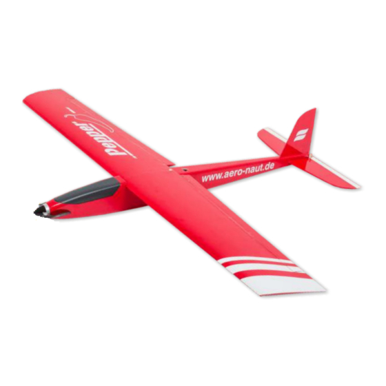
- Page 2 PEPPER is a sleek model with a considerable speed range. Building materials are mostly laser-cut balsa and light-ply to achieve a light yet strong structure, spruce is used to enhance the strength of the wing spars. For electric power choose a 28 mm brushless motor with a power of about 200 W. They all have a bolt circle diameter of 19/16 which will fit the model´s motor mount.
- Page 3 In a first step glue together main spar parts F1 A and F1 B. Use a straight edge against the spar´s building tabs for proper alignment F1 B and secure with tape. F1 A Assemble the 4-part wing jig, place on a flat building board and secure with tape.
- Page 4 At one end only splice leading edge F15 (4×4 mm obechi) and both spruce spars F16 (5×2 mm spruce) over a length of ca. 15 mm. Leading edge and spars must have a length of 1,110 and 1,150 mm, respectively. Fit and glue in place upper spar F16.
- Page 5 Glue together upper (F19 + F20) and lower (F21 + F22) wing sheeting and place on a flat surface. Immediately remove any excessive glue and secure with tape until dry. Glue in place upper wing sheeting of each wing half in two steps. Slightly chamfer front edge of upper wing sheeting for proper fit at leading edge.
- Page 6 Remove wing from jig and turn upside down. Break off building tabs and sand lightly to achieve a smooth contact surface on main spar and ribs. Glue in place lower spruce spar F16 and servo frames F23. From trailing edge triangular stock (8×40 mm) cut off two ca.
- Page 7 Install servo leads in wing and secure with tape in servo bay. Route opposite end of servo leads through hole in lower wing sheeting and glue wing sheeting in place. Use same proceedrue as with upper wing sheeting. Carefully sand flush rear edge of wing. Cut off one ca.
- Page 8 Cut off spars, leading and trailing edges at end ribs and carefully sand flush with contact surfaces of end ribs. Glue in place wing tips F26 (balsa triangular stock, 20×20 mm) on end rib and secure with pins. When dry, sand wing tips and leading edge to shape and give wing a smooth surface.
- Page 9 Glue together aileron servo mounts from 4 pieces F27 each. Align servo with servo arm centred in slot of servo tray F28, hold in place and glue servo mounts in place with a drop of medium CA. Insert servo in servo mounts and install servo tray in wing. Drill servo frame F23 with 1.5 mm and temporarily install screws F31.
- Page 10 Glue former R5 at right angles into servo tray R4 and glue former R8 at right angles into R7. Glue servo tray into former R3 at Check with set square or similar. right angles. R3, R4, R5 Place right fuselage side R1 A on flat building board and secure with pins.
- Page 11 Glue reinforcements for tailplane slot R13 and R14 to fuselage side. Temporarily insert former R11 into fuselage side as an end stop. Cut off two 375 mm and two 225 mm long pieces of 8×8 mm triangular stock R15. Place triangular stock on building board as shown and use a razor saw to make cuts at intervals of 15 to 20 mm over a length of 200 mm.
- Page 12 Glue triangular stock R15 on fuselage side along top and bottom contours as shown and secure with pins. Note: Bottom strip ends in front of former R3. Cut to length four pieces of 6×6 mm triangular stock R16 for top and bottom rear fuselage contours.
- Page 13 Glue in place canopy frame R17 on fuselage side along canopy cut-out. Remove any formers/assemblies from right fuselage side and build up left fuselage side R1 B accordingly. R3, R4, R5 Glue former R2 as well as assembly R3, R4, R5 in place on right fuselage side.
- Page 14 Make sure that left fuselage side R1 B fits perfectly on formers R1 B before you glue. Make corrections as necessary. Then glue in place left fuselage side on formers and glue R19 onto wing retainer R18. Glue former R11 into rear of fuselage (bore for elevator control faces up), glue together rear end of fuselage sides without sanding reinforcements R13, R14.
- Page 15 Glue in place formers R9 and R10. Please note that bores for elevator control are located in upper half of formers. Secure with tape wrapped around fuselage. Insert and glue R7/R8 into nose section, pulling together front of fuselage sides. Glue in place motor mount R20 and secure with clamps and tape.
- Page 16 Cut snake outer R21 to a length of 485 mm and glue into formers with 5 minute epoxy, so that it protrudes 30 mm from former R3 and 45 mm from former R11. Carefully sand top and bottom contact surfaces of fuselage, then glue in place fuselage sheeting.
- Page 17 Cut off sheeting material and triangular stock and sand flush with motor mount. Glue in place motor mount cover R30 (1.5 mm birch ply). Make sure bores in R19 match bores in motor mount perfectly. When glue has dried, sand fuselage to shape and round off edges. With a razor saw cut out canopy and remove from fuselage.
- Page 18 Fit wing into wing saddle and align with centre of fuselage. Through bore in former R2 mark position of wing dowel, then drill with 4 mm. Insert wing dowel F32 in wing and slide wing in place on fuselage. Make sure wing and dowel fit perfectly and without binding.
- Page 19 Fit canopy former R32 in place in fuselage. To achieve best results, bevel off contact surfaces with upper sheeting, triangular stock and canopy frame. From behind glue magnet R33 and retainer R34 to former (epoxy), then glue former R32 in place and secure with clamps. Fit canopy former R35 in place in rear end of canopy.
- Page 20 With drill and file make an opening in rear end of fuselage so that clevis for elevator control can move freely and without binding (ca. 6 mm wide, 7 mm high). If necessary, correct opening when elevator control is installed. Insert 0.8 mm piano wire R38 in snake R39.
- Page 21 Place tailplane R42 on building board (put cling film under- neath), secure with pins and glue tips R43 in place. Chamfer front edge of elevator R44 for sufficient controll throw. From above glue in place control horn R45 in elevator and sand front of control horn flush with front edge of elevator.
- Page 22 Mark contact surfaces of fin and tailplane and do not cover. Then cover components of model with your favourite covering material. Iron-on film is the quickest method to achieve an attractive finish. Because of ist texture we suggest you use for your Pepper iron-on fabric, which is available in many attractive colours.
-
Page 23: Parts List
Parts List P q0 Description Pieces Material Sheet Type Dimensions P q0 Description Pieces Material Sheet Type Dimensions R1 A right fuselage side balsa laser-cut 3 mm clevis metal ready made R1 B balsa laser-cut 3 mm balsa laser-cut 3 mm left fuselage side tailplane light ply... - Page 24 Here are some more models from our range ... Lilienthal 40 RC Wingspan 1,190 mm Free flying glider with RC option Laser-cut wood kit designed with beginners, schools and clubs in mind aero naut Luscombe Silvaire 1369/00 Laser-cut wood kit aero-naut Modellbau Stuttgarter Strasse 18-22 D-72766 Reutlingen...
Need help?
Do you have a question about the PEPPER and is the answer not in the manual?
Questions and answers