Advertisement
Quick Links
Advertisement

Related Manuals for APPA 76


Summary of Contents for APPA 76
- Page 1 RC METERPLUS INSTRUCTION MANUAL APPA 76...
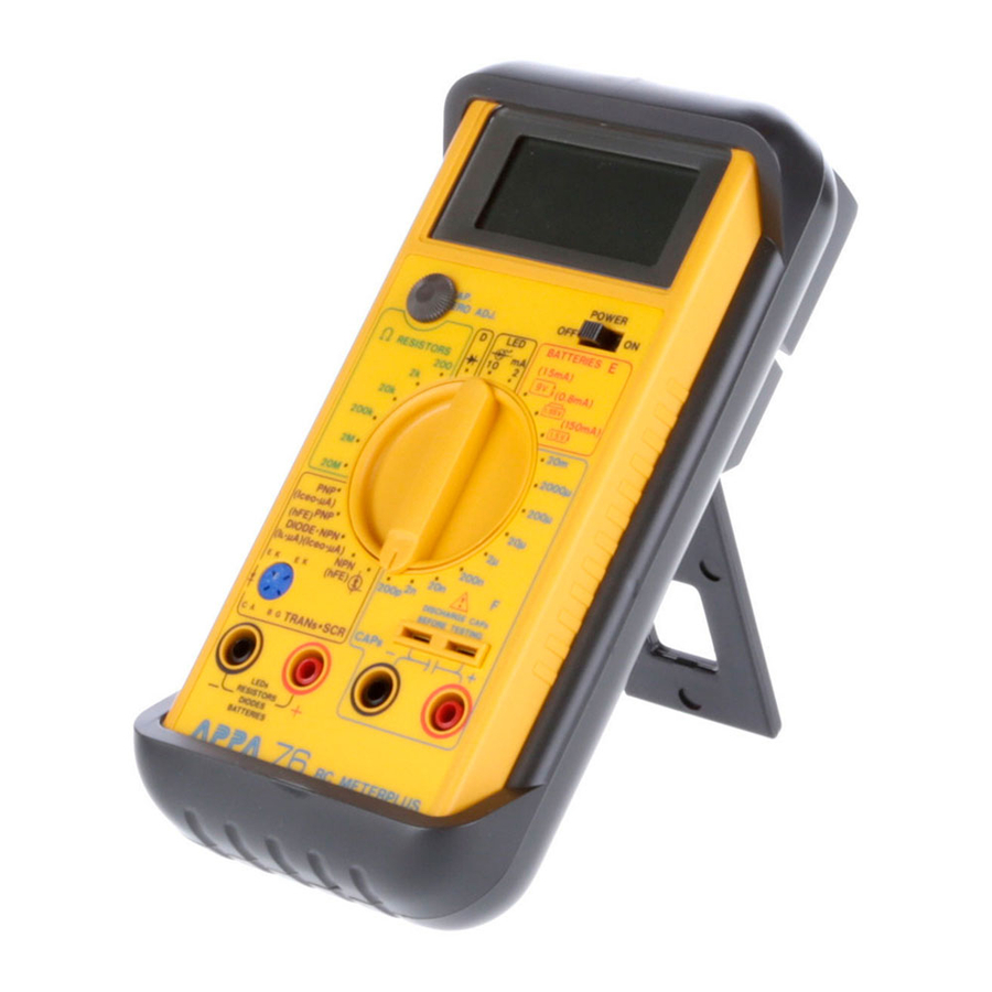
- Page 2 Introduction 1.1 Unpacking and checking Upon removing your new RC Meterplus from its packing, you should have the following items: 1. RC meterplus. 2. Test leads set (one black and one red). 3. Operating manual. 4. Protective holster. 1.2 Front Panel Refer to Figure 1 and the following nunberes steps to familiarize yourself with the meter’s front panel controls and connectors.
- Page 3 4. Rotary function and range switch — This switch is used to set the desired function and range. 5. Capacitance sockets — The terminals of capacitors can be inserted in these sockets to allow their capacitance to be measured directly. 6.
- Page 4 Figure 1...
-
Page 5: Specifications
Specifications 2.1 General specification Display : 31⁄2 digit 1999 count LCD display. Polarity indication : Automatic, positive implied negative indicated. Over range : "1" or "-1" Low battery voltage indication : " " shown if the voltage from the battery drops below the operating voltage. Measuring Tate : 2 times per second, nominal. - Page 6 2.2 Electrical specification Accuracy is ± (reading + number of digits) at 23°C ± 5°C, less than 75% RH. (1) Capacitance Range Resolution Accuracy Test frequency 200pF 0.1pF ±(0.5%rdg + 1dgt + 0.5pF) 20nF 10pF 820Hz 200nF 100pF ±(0.5%rdg + 1dgt) 2µF 20µF 10nF...
- Page 7 Testing voltage : 3.2V peak (max.). The (+) socket is always positive relative to the (-) socket. Input protection : The tester is protected against capacitor discharge (above 50V) by a 0.25A, 250V quick-acting fuse. Zeroing for capacitance : restricted to approx. ± 20pF (2) Resistance Max.
- Page 8 (3) Diode testing Max.open cuicuit Range Resolution Accuracy Max. test current voltage ±(1.5%rdg + 5dgt) 1.5mA 3.2V Overload protection: 500V DC/AC max. (4) LED Test Testing Voltage : 3.2V max. Test Current : 2mA or 10mA two ranges. LED lamp lighted test, display reading is LED forward voltage approx.
- Page 9 (5) Transistor hFE Test, Trainsistor Leakage Iceo Test 0 - 1000 hFE values either PNP or NPN transistor hFE Base Current : 10µA approx. hFE Vce : 3V approx. Iceo : 10nA - 20.00µA. (6) SCR Test SCR good/defect test. (7) Battery testing Battery type Load 9V Battery Load.
-
Page 10: Operation
OPERATION 3.1 Measuring capacitance WARNING : 1. Never apply voltage to the test terminals; this could damage or destroy the tester. 2. Fully discharge capacitors before testing them. 3. With polarised capacitors, make sure they are connected with the correct polarity. 4. - Page 11 4. If the capacitance of the capacitor you are going to measure is specified, set the appropriate range. If it is not, start with the 200pF range. If an over range is indicated, go to the next range up. Continue doing so until the over range annunciator disappears and a measurement is shown.
- Page 12 Note: 1. An open-circuited capacitor will show "0" on all the ranges (expect for a few pF on the 200pF range). 2. When using the 200pF range, you are advised always to use the short test leads if the measuring socket cannot be used in the particular case.
- Page 13 7. Capacitors (and particularly electrolytic capacitors) are often subject to wide tolerances. Hence the values measured are often up to 100% more than the nominal values but they are seldom drastically below them. 8. The tester uses an a.c. voltage method of measurement which is less subject to errors than the d.c. ramp voltage method when the capacitors being measured have high leakage currents, which electrolytic capacitors often do.
- Page 14 3.4 Testing transistor leakage current (ICEO) 1. Switch on tester (move on/off switch to "ON" position). 2. Turn rotary switch to the desired I range (PNP or NPN). 3. Connect the transistor straight into the transistor socket. The holes of the socket are marked E, B and C for emitter, base and collector.
-
Page 15: Battery Replacement
BATTERY REPLACEMENT The tester is powered by a single 9V battery. To change the battery, refer to Fig.2 and follow the instructions given below. 1. Remove the test leads from the component being tested, switch the tester off (move on/off switch to "OFF") and unplug the test leads from the input terminals. - Page 16 Bottom half of case 9V Battery Top half of case Battery Connector Figure 2...
-
Page 17: Fuse Replacement
FUSE REPLACEMENT To change or check the fuse, refer to Fig.3 and follow the instructions given below. 1. Carry out steps 1 to 3 of the instructions for changing the battery. 2. Lift the printed circuit board out of the top half of the case. Do not unscrew any of the screws in the printed circuit board. - Page 18 Top half of case Fuse Holster Fuse Bottom half of case Fuse 0.25A, 5 x 20mm, fast blow, 250V, HBC 1.0KA Figure 3...
- Page 19 HOW TO USE THE PROBE HOLDER Clip one probe on the holster for Wrap the leads around the one handed meter operation. holster to store the test probes.
- Page 20 HOW TO USE THE TILT STAND AND HOLSTER Swing the stand out for easier meter reading. Swing the upper holder out and hook it over a door.
- Page 21 HOW TO USE THE TILT STAND AND HOLSTER Meter in holster face down Hang on a nail at the workbench...
- Page 22 APPA TECHNOLOGY CORP. 9F.119-1 Pao-Zong Rd., Shin-Tien, Taipai, 23115, Taiwan, R.O.C. P.O.Box. 12-24 Shin-Tien, Taiwan. Tel : 886-2-29178820 Fax : 886-2-29170848 E-MAIL:info @appatech.com http://www.appatech.com Printed In Taiwan Copright 1997, APPA Tech., Corp. All rights reserved.
Need help?
Do you have a question about the 76 and is the answer not in the manual?
Questions and answers