Table of Contents

Related Manuals for FDS FD70ARM


Summary of Contents for FDS FD70ARM
- Page 1 Revision Date: Rev: Document Number: 05/22/2017 MAN – FD70ARM Page 1 of 13 Installation and Operation Manual FD70ARM 7” Widescreen LED on Arm © 2017 FDS Avionics Corp. TECHNICAL SUPPORT All Rights Reserved. 470-239-7421 or FDSAvionics.com...
-
Page 2: Table Of Contents
Monitor Control Buttons..................8 Remote Control Buttons..................9 Technical Drawing .................... 10 Technical Support ..................... 11 Instructions for Continued Airworthiness ............11 Warranty ......................12 Log of Revisions ....................13 © 2017 FDS Avionics Corp. TECHNICAL SUPPORT All Rights Reserved. 470-239-7421 or FDSAvionics.com... -
Page 3: General Information
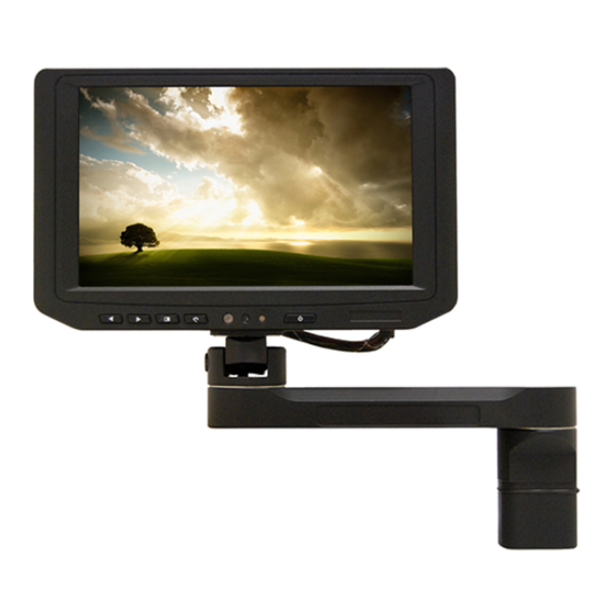
Page 3 of 13 General Information The FD70ARM is a 7” Widescreen LED on a pivoting, rotating Arm. Built with retrofit aircraft integration in mind, this display can switch between three video input sources using the buttons on the bezel or the Infrared Remote. -
Page 4: Specifications
DO-160 Sec. 7 Cat. B, PMA Approved Installation Instructions All cabin entertainment equipment, such as the FD70ARM, should be installed on a non- essential bus and have a dedicated circuit breaker. It is a requirement that a switch be installed in the cockpit so that the pilot can de-energize the entertainment system should it become necessary. -
Page 5: Wiring Suggestions
The individual wires should be extended with 6” 22awg wires using an environmental splice for the red & green wires, and Raychem caps for the blue, white, and black wires. © 2017 FDS Avionics Corp. TECHNICAL SUPPORT All Rights Reserved. -
Page 6: Mounting And Base Information
Page 6 of 13 Mounting and Base Information The FD70ARM mates with a drink rail mount, FDBASE (left), or a wall mount, FDBASE-W (right). The connector seats deeply in the mount and is held in place by either gravity or a locking pin. -
Page 7: Power/Video
Red Ground (Pin 6 on Standard VGA) Green Ground (Pin 7 on Standard VGA) Horizontal Sync (Pin 13 on Standard VGA) Vertical Sync (Pin 14 on Standard VGA) © 2017 FDS Avionics Corp. TECHNICAL SUPPORT All Rights Reserved. 470-239-7421 or FDSAvionics.com... -
Page 8: Operation Instructions
No pilot or aircrew action is necessary during flight or ground operation. The passengers will be able to change the video output from the FD70ARM using the video source select switch on the LED monitor, or remotely throughout the cabin with the included IR remote. -
Page 9: Remote Control Buttons
Revision Date: Rev: Document Number: 05/22/2017 MAN – FD70ARM Page 9 of 13 Remote Control Buttons See “Button Controls” above for Remote Control Button functions. Power Menu Source © 2017 FDS Avionics Corp. TECHNICAL SUPPORT All Rights Reserved. 470-239-7421 or FDSAvionics.com... -
Page 10: Technical Drawing
Revision Date: Rev: Document Number: 05/22/2017 MAN – FD70ARM Page 10 of 13 Technical Drawing © 2017 FDS Avionics Corp. TECHNICAL SUPPORT All Rights Reserved. 470-239-7421 or FDSAvionics.com... -
Page 11: Technical Support
05/22/2017 MAN – FD70ARM Page 11 of 13 Technical Support Should you have any questions concerning this product or other FDS Avionics Corp. products, please contact our Product Support representatives at (470) 239-7421. FDS Avionics Corp. 6435 Shiloh Road Alpharetta, GA 30005... -
Page 12: Warranty
Warranty Information All FDS Avionics Corp. products are warranted to be free from material or manufacturing defects for a period of 24 months from the date of shipment for General Aviation customers or 12 months from the date of shipment for Government/Special Mission customers. -
Page 13: Log Of Revisions
Page 13 of 13 Log of Revisions Date Page Description 01/25/2007 Initial Release 03/28/2007 2,6,7 Added info regarding FD70ARM (28V) 06/28/2007 Added remote pictures 02/26/2009 2,11 Updated specifications, warranty info 07/20/2009 Updated FAA/PMA Approval 08/17/2010 1,2,4,8,9,13 Added LED monitor, Format Change...
Need help?
Do you have a question about the FD70ARM and is the answer not in the manual?
Questions and answers