Table of Contents
Advertisement
Quick Links
Advertisement
Table of Contents

Subscribe to Our Youtube Channel
Related Manuals for Speco O4P30X


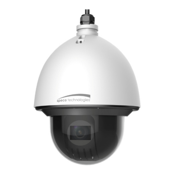
Summary of Contents for Speco O4P30X
- Page 1 Quick Start Guide 4MP 30X PTZ IP Camera O4P30X Version 1.0.1...
-
Page 2: Table Of Contents
Table of Contents DEVICE CHECK AND INSTALLATION ................1 1.1 Installation Requirements ..................1 1.2 Check Accessories ..................... 1 1.3 Open the Device ....................... 1 1.4 SD Card Installation ....................2 1.5 Reset ........................2 1.6 Speed Dome Installation ................... 3 1.6.1 Quick Installation port ................... - Page 3 APPENDIX IV WIRE GAUGE REFERENCE ..............13...
- Page 4 Thank you for purchasing this Network camera! This manual is designed to be a reference tool for your system. Please read this manual carefully before operating the unit and retain it for future reference. Should you require any technical assistance, please contact Speco Technologies Technical Support.
- Page 5 Important Safeguards and Warnings 1. . . . Electrical safety All installation and operation here should conform to local electrical safety codes. Use a certified/listed 12VDC Class 2 power supply only. Please note: Do not connect two power supplying sources to the device at the same time; it may result in device damage! The product must be grounded to reduce the risk of electric shock.
- Page 6 Before installation, check the package and make sure that all components are included. Keep the package material in case the camera needs to be sent back for service or repair. Contact your rep or Speco customer service department immediately if something is broken or missing in the package.
-
Page 7: Device Check And Installation
1.2 Check Accessories Before installation, check the package and make sure that all components are included. Contact your rep or Speco customer service department immediately if something is broken or missing in the package. Accessory Name... -
Page 8: Sd Card Installation
Figure 1-1 1.4 SD Card Installation Remove the bracket component; open the cover and locate the micro-SD card slot on the module ISP board (see Figure 1-2). Figure 1-2 1.5 Reset Locate the reset button on the PTZ mainboard after you remove the bracket component. See Figure 1-3. -
Page 9: Speed Dome Installation
Figure 1-3 1.6 Speed Dome Installation 1.6.1 Quick Installation port Now you can install the quick installation port. Please twist Teflon tape around the screw thread of the quick installation port and turn it into the screw thread of the wall mount bracket. -
Page 10: Install The Speed Dome
Connect the necessary cables. 1.6.3 Install the speed dome Step 1 Pull the cable to the wall mount bracket slowly. Step 2 Line up the straight edge of the flange of the speed dome to the straight edge of the quick installation port, and then push the speed dome to the bottom of the port slowly. - Page 11 Figure 1-6...
-
Page 12: Bracket Dimensions
2 Bracket Dimensions 2.1 Wall Mount Bracket The wall mount bracket dimensions are shown as below. See Figure 2-1. Figure 2-1... -
Page 13: Wall Mount Installation
3 Wall Mount Installation 3.1 Component Installation Wall mount bracket is shown as below. See Figure 3-1. Figure 3-1 3.2 Installation 3.2.1 Installation Requirements The wall mount speed dome can be installed on a hard surface wall. Before the installation, please make sure: The wall is thick enough to install the expansion bolt. - Page 14 Figure 3-2 Step 2 Install the speed dome on the bracket. See Figure 3-3. Please refer to section 1.6 Speed Dome Installation for more details. Figure 3-3...
-
Page 15: Ip Scanner
4 IP Scanner Overview IP Scanner can search for the device on the local network. IP Scanner can search for the device on the local network. Please note that only devices that are on the same subnet can be discovered. Please note that only devices that are on the same subnet can be discovered. -
Page 16: Web Operation
5 Web Operation This device supports viewing and management via a web browser on This device supports viewing and management via a web browser on a PC. Login and Main Interface Login and Main Interface Open the browser and input network camera address in the address bar or double click the Open the browser and input network camera address in the address bar or double click the Open the browser and input network camera address in the address bar or double click the device in IP Scanner. -
Page 17: Appendix Surge Protection
6 APPENDIX Ⅰ Ⅰ Ⅰ Ⅰ Surge Protection This device uses TVS lighting protection technology. It can effectively prevent damages from various pulse signals below 2000W, such as sudden lighting and surge. While maintaining your local electrical safety code, you still need to take necessary precaution measures when installing the speed dome in an outdoor environment. -
Page 18: Relationship
7 APPENDIX Ⅲ Ⅲ Ⅲ Ⅲ 24V AC Cable Diameter and Transmission Distance Relationship It is the recommended transmission distance when the cable diameter is fixed and the 24V AC power consumption is below 10%. For the AC device, the max permission voltage power consumption is 10%. - Page 19 8 APPENDIX IV Wire Gauge Reference Metric bare wire Bare wire cross section diameter ( ) ( ) 0.050 0.00196 0.060 0.00283 0.070 0.00385 0.080 0.00503 0.090 0.00636 0.100 0.00785 0.110 0.00950 0.130 0.01327 0.140 0.01539 0.160 0.02011 0.180 0.02545 0.200 0.03142 0.230...
Need help?
Do you have a question about the O4P30X and is the answer not in the manual?
Questions and answers