
Related Manuals for Speco Intensifier OiMD1


Summary of Contents for Speco Intensifier OiMD1
- Page 1 OiMD1 OiMD1 ® Intensifier HD Megapi HD Megapixel Indoor/Outdoor xel Indoor/Outdoor Miniature Dome IP Camera Miniature Dome IP Camera...
- Page 2 ’ ’ Directions Be careful not to cause any physical damage by dropping or throwing the camera. Especially keep the device out of reach from children. Do not disassemble the camera. No after service is assumed when disassembled. Use only power adapters compatible with the unit. Be careful to prevent moisture or water penetration into the unit.
- Page 3 ’ ’ Revision History Date Revision Details Jun 1 , 2014 First manual revision creation. Jul 9 , 2014 1.0.1 Minor revisions Jul 11 , 2014 1.0.2 Minor revisions Rev.1.0.2(Jul. 2014)
-
Page 4: Table Of Contents
Quick Installation Guide ........................16 4.2.1. Connect PC and OiMD1 to network..................16 4.2.2. Install Speco-NVR and set IP parameters on OiMD1 .............. 16 4.2.3. Remote video connection to OiMD1 ..................18 4.2.4. Additional settings through connection to the Admin Page ............20 Trouble Shooting ............................ -
Page 5: Introduction
It enables real time transmission of synchronized video of up to 1080p and audio data. Remote clients can connect to ONSIP OiMD1 for the real time video/audio data through various client solutions running on PC, PDA or mobile phones. Real time 2-way communication is available through bidirectional audio communication feature. -
Page 6: Specifications
’ ’ 1.2. Specifications Camera Image sensor Progressive scan 1/3 inch CMOS 1.3M pixels Full resolution 1,280 x 720 pixels (HD) Min. illumination Color : 0.0005 Lux (F1.2) Sync System Internal S/N Ratio 62dB or more Lens 3.7mm Day & Night Sensitivity Intensifier OFF - 0.12 Lux (F1.2, 30 IRE , ICR B/W) - Page 7 Network Protocol - RTP, RTSP, SDP, HTTP, SMTP, FTP, DHCP, UPnP - NTP, DNS, DynDNS Dynamic IP Speco DDNS (free of charge) - User ID & Password protection, IP address filtering Security - Digest Authentication, User Access Log - RTSP streaming with proprietary format for control information...
-
Page 8: Applications Of Oimd1
’ ’ 1.3. Applications of OiMD1 Security surveillance (buildings, stores, manufacturing facilities, parking lots, banks, government facilities, military, etc.) Remote monitoring (hospitals, kindergartens, traffic, public areas, etc.) Teleconference (Bi-directional audio conference). Remote Learning, Internet broadcasting Weather and environmental observation Rev.1.0.2(Jul. 2014) -
Page 9: Product Description
The product package contains followings : contains followings : Contents Description Remarks OiMD1 OiMD1 main unit CVBS Cable 1EA, Screws (3 pieces of 1 type), Accessories Anchors (3 pieces of 1 type), L-type wrench with six angles 1EA Software & User’s Guide... -
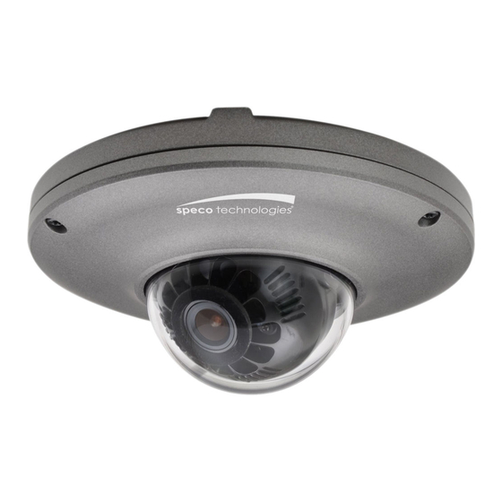
Page 10: Physical Description
’ ’ 2.3. Physical description 2.3.1. External View Figure 2-1. External view of OiMD1 2.3.2. Dimensions Unit : mm Figure 2-2. Dimensions Rev.1.0.2(Jul. 2014) -
Page 11: External Connector
’ ’ 2.3.3. External Connector Line Output Network (LAN) Sensor Input (white(+), Red(-)) Relay Output (Black(+), Yellow(-)) Mic/Line Input Power Figure 2-3. Connector for external connection 2.3.4. Factory Default Switch Factory default switch is provided for returning the IP camera to factory default state. Unscrew the cover to access the switch. -
Page 12: Functional Description
Power : Power input for supplying Power input for supplying 12V DC power. Caution : If OiMD1 is powered by PoE, do not plug in DC Jack with active DC power is powered by PoE, do not plug in DC Jack with active DC power is powered by PoE, do not plug in DC Jack with active DC power into DC power connector. - Page 13 ’ ’ Sensor Input Connect external alarm sensor. Examples of sensing devices are infrared sensor, motion sensor, heat/smoke sensor, magnetic sensor, etc. Connect the two wires of the sensors to “Sensor Input”. The sensor type (NC/NO) can be set in admin page. Multiple sensor devices can be connected in parallel. NO/NC Type Open Collector Type Photo Coupler...
-
Page 14: On Site Installation
’ ’ 3. On Site Installation Use cables and conduits that are suitable for the installation. Particular attention should be paid in the Use cables and conduits that are suitable for the installation. Particular attention should be paid in the Use cables and conduits that are suitable for the installation. -
Page 15: Getting Started
Brief information for first time operation of OiMD1 is provided in this chapter. 4.1. PC Requirement Audio/Video streaming data received from OiMD1 can be displayed or stored in a PC running client programs. Minimum requirement of the PC is described below:... -
Page 16: Quick Installation Guide
If your LAN Switch does not support standard PoE, connect your LAN Switch does not support standard PoE, connect OiMD1 as shown in dotted line in Figure 4 as shown in dotted line in Figure 4-1. - Page 17 ’ ’ Follow the sequence below for setting the IP parameter Follow the sequence below for setting the IP parameter Run ONSIP installer Click (1) in ONSIP installer window.> Double click on (2) > Fill in (4) > make a selection in (5) > Fill (1) in ONSIP installer window.>...
-
Page 18: Remote Video Connection To Oimd1
1. Connection through Web Viewer Web Viewer offers simplest way of video connection to Web Viewer offers simplest way of video connection to OiMD1. For video connection, enter the IP . For video connection, enter the IP address of OiMD1 in the URL window of Internet Explorer as:... - Page 19 When you exit Speco-NVR, you have to input the ID/PW, admin/1234. Details for Speco NVR, you have to input the ID/PW, admin/1234. Details for Speco-NVR can be found in NVR can be found in [Speco-NVR User’s Guide].
-
Page 20: Additional Settings Through Connection To The Admin Page
’ ’ 4.2.4. Additional settings through connection to the Admin Page All parameters of the camera are factory default out of the box. For a more sophisticated target application, parameters need to be changed through the admin page. The admin page can be connected through “http://IP_Address:Port_Number/admin.htm”... -
Page 21: Troubleshooting
’ ’ 5. Troubleshooting 5.1. No power is applied In case of Standard PoE (Power over Ethernet) Power supply through standard PoE is possible only when the following conditions are met. 1. Standard PoE is supported on the product. 2. The LAN switch supports standard PoE. Make sure that both the IP camera and the LAN switch support standard PoE (IEEE 802.3af) In case of DC adapter If PoE is not applied, the power and network connection should be made through separate cables. -
Page 22: Cannot Connect To The Video
’ ’ 5.2. Cannot connect to the Video Check the status of the network connection through PING test. Try the following on your PC : Start > Run > Cmd > Ping IP address (Ex : Ping 172.16.42.51) If “Reply from ~” message is returned ( in the figure below), the network connection is in normal ①... -
Page 23: Windows Vista Or Windows 7
Windows Vista and Windows 7 users need to configure UAC (User Access Control) and Privilege Level for proper recording and still video capture in Speco proper recording and still video capture in Speco-NVR and Web Viewer. <Windows Vista> 1. UAC (User Access Control) configuration 1. - Page 24 ’ ’ <Windows 7> 1. UAC (User Access Control) configuration 1. UAC (User Access Control) configuration 1) Double-click “User Accounts” in control panel click “User Accounts” in control panel 2) Double-click “Change User Account C click “Change User Account Control setting” 3) Set to “Never notify”...
- Page 25 ’ ’ 2. Privilege Level Control 1) Select “NVR” icon on the desktop 2) Click right mouse button and select “properties” 2) Click right mouse button and select “properties” 3) Check “Privilege Level” in “Compatibility” tab 3) Check “Privilege Level” in “Compatibility” tab...
-
Page 26: Technical Assistance
’ ’ 5.4. Technical Assistance If you need any technical assistance, please contact If you need any technical assistance, please contact technical support. For immediate service please . For immediate service please provide the following information. Model name 1 . 1 . 1 . 1 . MAC address and Registration number MAC address and Registration number 2 . -
Page 27: Appendix A - Important Notice In Exchanging Sd Card (Micro Sd)
’ ’ Appendix A – Important Notice in Exchanging SD Card (Micro SD) SD Card is a non-volatile memory device for storing video and audio data on the product. Note that continuous recording to the SD Card will cause the memory cell to wear out, eventually resulting in failure. When you plug out the SD Card for replacement or other purpose, follow the steps below in order to prevent data loss or crash of the SD Card.
Need help?
Do you have a question about the Intensifier OiMD1 and is the answer not in the manual?
Questions and answers