Table of Contents
Advertisement
Advertisement
Table of Contents

Related Manuals for Speco O3VFBM


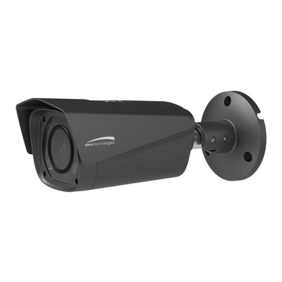
Summary of Contents for Speco O3VFBM
- Page 1 Quick Start Guide 3MP VF Motorized Bullet IP Camera O3VFBM Version 1.0.1...
- Page 2 This owner’s manual is designed to be a reference tool for your system. Please read this manual carefully before operating the unit and retain it for future reference. Should you require any technical assistance, please contact Speco Technologies Technical Support.
- Page 3 Important Safeguards and Warnings 1.Electrical safety All installation and operation here should conform to local electrical safety codes. Use a certified/listed 12VDC Class 2 power supply only. Please note: Do not connect two power supplying sources to the device at the same time; it may result in device damage! The product must be grounded to reduce the risk of electric shock.
- Page 4 Speco Technologies is not liable for any loss caused by improper operation. Note: Before installation, check the package and make sure that all components are included. Contact your rep or Speco customer service department immediately if something is broken or missing in the package. Accessory Name...
-
Page 5: Table Of Contents
Table of Contents Physical Specifications ......................1 Device External Cable ...................... 1 Dimensions ........................1 Device Installation ....................... 3 IP Scanner ........................... 6 Overview ......................... 6 Operation ........................6 Web Operation ........................7 Login and Main Interface ....................7... -
Page 6: Physical Specifications
1 Physical Specifications Device External Cable You can refer to the following figure for cable information. See Figure 1-1. Figure 1-1 Please refer to the following sheet for detailed information. Port name Function description Ethernet port Network data in/out and PoE DC power Connect to DC 12V power jack... - Page 7 Figure 1-2 Dimension illustration 2 Figure 1-3 Dimension illustration 3...
-
Page 8: Device Installation
2 Device Installation Note: Before installation, please make sure the installation surface can support a minimum of 3 times the weight of the camera Figure 2-1 Step 1 Install Micro SD card Open the lower cover, find the Micro SD card slot as shown in Figure 2-2, insert it into the slot and make sure it is firmly latched in the slot. - Page 9 Figure 2-2 Step 2 Fix the device on the installation surface. 1. Take out the installation template from the accessories bag, paste it on the surface (wall or ceiling) and drill holes according to the hole locations marked on the template. 2.
- Page 10 1. Use the inner hex screwdriver to loosen the adjusting screws shown in the figure above. 2. Adjust the device monitoring direction according to the requirements. 3. Use the screwdriver to tighten the adjusting screws. Step 5 Waterproof connector installation for network port; see Figure 2-4 for more details. Note: Please implement this step if the device is used outdoors.
-
Page 11: Ip Scanner
3 IP Scanner 3.1 Overview IP Scanner can search for the device on the local network. Please note that only devices that are on the same subnet can be discovered. 3.2 Operation Open up IP Scanner. Figure 3-1 In the device list, you can view the IP address, model number, and MAC address of each device. -
Page 12: Web Operation
4 Web Operation This device supports viewing and management via a web browser on a PC. Login and Main Interface Open the browser and input network camera address in the address bar or double click the device in IP Scanner. See Figure 4-1. Input your IP address here Figure 4-1 IP address...
Need help?
Do you have a question about the O3VFBM and is the answer not in the manual?
Questions and answers