GE 750 Instruction Manual
Feeder management
Hide thumbs
Also See for 750:
- Instruction manual (450 pages) ,
- Manual (102 pages) ,
- Quick reference manual (58 pages)
Table of Contents
Advertisement
Quick Links
Download this manual
See also:
Manual
g
GE Power Management
215 Anderson Avenue, Markham, Ontario
Canada L6E 1B3
Tel: (905) 294-6222 Fax: (905) 294-8512
Internet: http://www.GEindustrial.com/pm
Courtesy of NationalSwitchgear.com
FEEDER MANAGEMENT RELAY
Instruction Manual
Manual P/N: 1601-0044-AL (GEK-106293A)
Copyright © 2002 GE Power Management
760 STATUS
SYSTEM STATUS
RELAY IN SERVICE
BREAKER OPEN
TRIP
BREAKER CLOSED
RECLOSURE
ALARM
ENABLED
RECLOSURE
PICKUP
DISABLED
SETPOINT
RECLOSURE
GROUP 1
IN PROGRESS
SETPOINT
RECLOSURE
GROUP 2
LOCKOUT
SETPOINT
LOCAL
GROUP 3
RESET
OPEN
BREAKER
SETPOINT
REMOTE
GROUP 4
NEXT
CLOSE
PROGRAM PORT
PROGRAM PORT
7
SETPOINT
MESSAGE
4
ACTUAL
1
CLEAR
VALUE
.
STORE
g
760
Feeder Management
GE Power Management
750/760
Firmware Rev.: 402-000
Analog Rev.: 27H402A4.000
Control Rev.: 27H402C4.000
OUTPUT STATUS
1 TRIP
2 CLOSE
3 AUXILIARY
4 AUXILIARY
5 AUXILIARY
6 AUXILIARY
7 AUXILIARY
SELF-TEST
8
WARNING
8
9
5
6
2
3
0
HELP
®
818789A3.CDR
®
Manufactured under an
ISO9001 Registered system.
Advertisement
Table of Contents

Related Manuals for GE 750


Summary of Contents for GE 750
- Page 1 750/760 ® FEEDER MANAGEMENT RELAY Instruction Manual Firmware Rev.: 402-000 Analog Rev.: 27H402A4.000 Control Rev.: 27H402C4.000 Manual P/N: 1601-0044-AL (GEK-106293A) Copyright © 2002 GE Power Management 760 STATUS SYSTEM STATUS OUTPUT STATUS RELAY IN SERVICE BREAKER OPEN 1 TRIP TRIP...
- Page 2 Courtesy of NationalSwitchgear.com...
- Page 3 WARNING These instructions do not purport to cover all details or variations in equipment nor provide for every possible contingency to be met in connection with installation, operation, or maintenance. Should further information be desired or should particular problems arise which are not covered sufficiently for the purchaser’s purpose, the matter should be referred to the General Electric Company.
- Page 4 Courtesy of NationalSwitchgear.com...
-
Page 5: Table Of Contents
PHASE TIME O/C 1................... 2-6 b PHASE INSTANTANEOUS O/C 1............. 2-7 c PHASE INSTANTANEOUS O/C 2............. 2-7 d NEUTRAL TIME O/C 1 ................2-7 e NEUTRAL INSTANTANEOUS O/C 1 ............2-7 GE Power Management 750/760 Feeder Management Relay Courtesy of NationalSwitchgear.com... - Page 6 DESCRIPTION ..................4-1 4.1.2 HARDWARE AND SOFTWARE REQUIREMENTS ........4-1 4.1.3 HARDWARE CONFIGURATION ............... 4-1 4.2 INSTALLATION / UPGRADE 4.2.1 750/760 PC PROGRAM UPGRADING............4-2 4.2.2 INSTALLATION ..................4-3 4.3 750/760 PC MAIN WINDOW 4.3.1 MAIN WINDOW SCREEN ................. 4-4 4.3.2 TOP LEVEL MENU SUMMARY ..............
- Page 7 5. FRONT PANEL 5.1 DESCRIPTION OPERATION 5.1.1 DESCRIPTION ..................5-1 5.2 STATUS INDICATORS 5.2.1 DESCRIPTION ..................5-2 5.2.2 750/760 STATUS INDICATORS..............5-2 5.2.3 SYSTEM STATUS INDICATORS.............. 5-2 5.2.4 OUTPUT STATUS INDICATORS.............. 5-3 5.3 KEYPAD OPERATION 5.3.1 DESCRIPTION ..................5-4 5.4 MESSAGES 5.4.1...
- Page 8 8.5.1 DESCRIPTION ..................8-5 8.5.2 SETTINGS ....................8-5 8.6 TRACE MEMORY 8.6.1 DESCRIPTION ..................8-6 8.6.2 SETTINGS ....................8-6 8.7 DATA LOGGER 8.7.1 DESCRIPTION ..................8-7 8.7.2 SETTINGS ....................8-7 750/760 Feeder Management Relay GE Power Management Courtesy of NationalSwitchgear.com...
- Page 9 10.3 BREAKER FUNCTIONS 10.3.1 DESCRIPTION ..................10-4 10.3.2 SETTINGS ....................10-4 10.4 CONTROL FUNCTIONS 10.4.1 SETTINGS ....................10-5 10.5 USER INPUT FUNCTIONS 10.5.1 DESCRIPTION ..................10-6 10.5.2 SETTINGS ....................10-6 GE Power Management 750/760 Feeder Management Relay Courtesy of NationalSwitchgear.com...
- Page 10 12.3.2 NEUTRAL TIME OVERCURRENT ............12-16 12.3.3 NEUTRAL INSTANTANEOUS OVERCURRENT ........12-18 12.3.4 NEUTRAL DIRECTIONAL ..............12-20 12.4 GROUND OVERCURRENT 12.4.1 DESCRIPTION ..................12-23 12.4.2 GROUND TIME OVERCURRENT............12-23 12.4.3 GROUND INSTANTANEOUS OVERCURRENT........12-25 750/760 Feeder Management Relay GE Power Management Courtesy of NationalSwitchgear.com...
- Page 11 13.3.2 SETPOINTS..................... 13-8 13.4 DEMAND 13.4.1 DESCRIPTION ..................13-9 13.4.2 CURRENT DEMAND................13-10 13.4.3 REAL POWER DEMAND ..............13-12 13.4.4 REACTIVE POWER DEMAND.............. 13-14 13.4.5 APPARENT POWER DEMAND ............13-16 GE Power Management 750/760 Feeder Management Relay Courtesy of NationalSwitchgear.com...
- Page 12 14.7.4 LOGIC INPUTS FOR INCOMER #1, #2, & BUS TIE RELAYS ..... 14-21 14.8 AUTORECLOSE (760 ONLY) 14.8.1 DESCRIPTION ..................14-30 14.8.2 SCHEME SETUP................... 14-31 14.8.3 AUTORECLOSE RATE SUPERVISION..........14-33 14.8.4 AUTORECLOSE CURRENT SUPERVISION........14-35 14.8.5 AUTORECLOSE ZONE COORDINATION ..........14-36 750/760 Feeder Management Relay GE Power Management viii Courtesy of NationalSwitchgear.com...
- Page 13 15.4.5 POSTFAULT VALUES................15-9 15.5 FACTORY SERVICE 15.5.1 DESCRIPTION ..................15-10 15.5.2 SETPOINTS................... 15-10 16. COMMUNICATIONS 16.1 OVERVIEW 16.1.1 750/760 COMMUNICATIONS FEATURES ..........16-1 16.2 PHYSICAL LAYER 16.2.1 DESCRIPTION ..................16-2 16.3 MODBUS PROTOCOL 16.3.1 DESCRIPTION ..................16-3 16.3.2 DATA LINK LAYER.................. 16-3 16.3.3 CRC-16 ALGORITHM................
- Page 14 FORWARD TRIPPING AND WYE CONNECTED VTs ......17-25 b FORWARD TRIPPING AND DELTA CONNECTED VTs ...... 17-26 17.7.8 NEUTRAL TIME OVERCURRENT 1 ............. 17-26 17.7.9 NEUTRAL TIME OVERCURRENT 2 ............. 17-26 750/760 Feeder Management Relay GE Power Management Courtesy of NationalSwitchgear.com...
- Page 15 17.9.3 MANUAL CLOSE FEATURE BLOCKING ..........17-56 a CONTROL OF O/C PROTECTION FEATURES ........17-56 17.9.4 COLD LOAD PICKUP FEATURE BLOCKING ........17-58 a CONTROL OF O/C PROTECTION FEATURES ........17-58 17.9.5 UNDERVOLTAGE RESTORATION ............17-60 GE Power Management 750/760 Feeder Management Relay Courtesy of NationalSwitchgear.com...
- Page 16 A.1 FIGURES AND TABLES A.1.1 LIST OF FIGURES ..................A-1 A.1.2 LIST OF TABLES..................A-3 B. EU DECLARATION OF B.1 EU DECLARATION OF CONFORMITY CONFORMITY C. WARRANTY C.1 WARRANTY INFORMATION C.1.1 WARRANTY ....................C-1 750/760 Feeder Management Relay GE Power Management Courtesy of NationalSwitchgear.com...
-
Page 17: Product Overview
To simplify programming and to provide a more intuitive interface, programming can be accomplished with a personal computer running the 750/760 PC program provided with each relay. Even with minimal computer knowledge, this menu-driven program provides easy access to all front panel functions. -
Page 18: Summary Of Features
1 Solid-State Trip • Energy (MWh, Mvarh) • 8 Analog Transducers • Last and Maximum Demand , MW, Mvar, MVA) • Analog Input Magnitude • Analog Input Rate (per minute, per hour) 750/760 Feeder Management Relay GE Power Management Courtesy of NationalSwitchgear.com... - Page 19 (With Protection Modification and Current Supervi- sion and Zone Coordination) • Prefault, Fault and Postfault Simulation • Breaker Open & Close • Product Firmware in Flash Memory (Upgrades via RS232 Port) GE Power Management 750/760 Feeder Management Relay Courtesy of NationalSwitchgear.com...
- Page 20 1.1 INTRODUCTION 1 PRODUCT OVERVIEW Figure 1–1: PROTECTION ONE LINE DIAGRAM 750/760 Feeder Management Relay GE Power Management Courtesy of NationalSwitchgear.com...
-
Page 21: Using This Manual
Section 1.2: TECHNICAL SPECIFICATIONS of this chapter. The remainder of this manual should be read and kept for reference to ensure maximum benefit from the 750 and 760. For further information, please consult your local sales representative or the factory. Comments about new features or modifications for your specific requirements are welcome. -
Page 22: Order Code
RS-232/485: RS232 to RS485 converter box for harsh industrial environments. 5A PHASE CT: 50, 75, 100, 150, 200, 250, 300, 350, 400, 500, 600, 750,1000. 1A PHASE CT: 50, 75, 100, 150, 200, 250, 300, 350, 400, 500, 600, 750,1000. -
Page 23: Technical Specifications
< 0.1 x CT: ± 0.2% of 1 x CT at ≥ 0.1 x CT: ± 1% of 1 x CT Overload Withstand: 1 second @ 80 times rated current continuous @ 3 times rated current GE Power Management 750/760 Feeder Management Relay Courtesy of NationalSwitchgear.com... -
Page 24: Measured Parameters
3Φ REAL POWER time interval (programmed): 5, 10, Range: –3000.0 to 3000.0 MW 15, 20, 30, or 60 min. Accuracy: ± 1% of full scale Accuracy: ± 2% of full scale * 750/760 Feeder Management Relay GE Power Management Courtesy of NationalSwitchgear.com... -
Page 25: Protection Elements
(For voltage element polarizing, the source VTs must be connected in Wye). Polarizing Voltage: –Vo Polarizing Current: MTA: 0 to 359° in steps of 1° Angle Accuracy: ± 2° Operation Delay: 25 to 40 ms GE Power Management 750/760 Feeder Management Relay Courtesy of NationalSwitchgear.com... - Page 26 Timing Accuracy: ± 100 ms IAC Extreme/Very/Inverse/Short Curve Multiplier: 0.00 to 100.00 in steps of 0.01 Reset Type: Instantaneous/Linear Level Accuracy: 3 x voltage input error Timing Accuracy: ±50 ms 750/760 Feeder Management Relay GE Power Management Courtesy of NationalSwitchgear.com...
-
Page 27: Monitoring Elements
Pulse output is 1 second on time and one second off time Timing Accuracy: at 60 Hz: ± 34 ms after the programmed interval. at 50 Hz: ± 40 ms GE Power Management 750/760 Feeder Management Relay Courtesy of NationalSwitchgear.com... -
Page 28: Control
Up to four reclose attempts before lockout. Each reclose shot can block instantaneous overcurrent, and raise pickup of time overcurrent elements. Current supervision can adjust the maximum number of shots to be attempted. 750/760 Feeder Management Relay GE Power Management Courtesy of NationalSwitchgear.com... -
Page 29: Other Features
Trigger Source: Element pickup/trip/dropout, control/ alarm event, logic input or manual command Trigger Position: 0 to 100% Storage capacity: 2 to 16 events with 2048 to 256 samples of data respectively GE Power Management 750/760 Feeder Management Relay Courtesy of NationalSwitchgear.com... -
Page 30: Outputs
Panel or 19" rack mount Temperature: -40 °C to +80 °C Weight Humidity: up to 90% noncondensing (Case and Relay): 7.9 kg Pollution Degree: Shipping Weight: 9.4 kg IP Rating: 40-X 750/760 Feeder Management Relay GE Power Management Courtesy of NationalSwitchgear.com... -
Page 31: Testing
Specifications subject to change without notice. It is recommended that all relays must be powered up at least once per year to avoid deterio- ration of electrolytic capacitors and subsequent relay failure. GE Power Management 750/760 Feeder Management Relay Courtesy of NationalSwitchgear.com... -
Page 32: Theory Of Operation
Both current and voltage are sampled sixteen times per power frequency cycle with frequency tracking control. These ‘raw’ samples are calibrated in software and then placed into the waveform capture buffer thus emulat- ing a fault recorder. The waveforms can be retrieved from the relay via the 750/760 PC Program for display and diagnostics. -
Page 33: Protection Elements
Contact inputs are debounced to eliminate false operations due to noise. The inputs must be in the same state for three consecutive readings spaced evenly over one power frequency cycle before a new state is recog- nized. GE Power Management 750/760 Feeder Management Relay Courtesy of NationalSwitchgear.com... - Page 34 1.3 THEORY OF OPERATION 1 PRODUCT OVERVIEW Figure 1–3: HARDWARE BLOCK DIAGRAM 750/760 Feeder Management Relay GE Power Management Courtesy of NationalSwitchgear.com...
-
Page 35: Getting Started
E S C A P E the display to the previous level. Press the key twice to return to the [ENTER] for more E S C A P E sub-page header. A2 METERING \ DEMAND GE Power Management 750/760 Feeder Management Relay Courtesy of NationalSwitchgear.com... -
Page 36: Settings
[ENTER] for more ARCING CURRENT TOTAL ARCING CURRENT MESSAGE E N T E R φA: [ENTER] for more - cycle TOTAL ARCING CURRENT MESSAGE φB: - cycle Figure 2–1: PANEL KEYING EXAMPLE 750/760 Feeder Management Relay GE Power Management Courtesy of NationalSwitchgear.com... -
Page 37: Changing Setpoints
The 750/760 numeric keypad works the same as any electronic calculator. A number is entered one digit at a time with the 0 to 9 and decimal keys. The leftmost digit is entered first and the rightmost digit is entered last. -
Page 38: Output Relay Setpoints
Re-enter the character as required. Once complete, press the key to remove the solid cursor E S C A P E and view the result. 750/760 Feeder Management Relay GE Power Management Courtesy of NationalSwitchgear.com... -
Page 39: Sample Application
2.3 SAMPLE APPLICATION 2.3.1 APPLICATION EXAMPLE The 750 and 760 relays contain many features designed to accommodate a wide range of applications. This chapter is provided to guide you, the first time user, through a real-world application. The following step-by- step installation example, provides you with a quick and convenient way of becoming familiar with the relay. -
Page 40: C Power System
S5 PROTECTION \ PHASE CURRENT \ PHASE TIME OC 1 \ Trip PHASE TIME OC 1 FUNCTION: 1.40 x CT (840A pickup / 600A CT pri) PHASE TIME OC 1 PICKUP: 750/760 Feeder Management Relay GE Power Management Courtesy of NationalSwitchgear.com... -
Page 41: B Phase Instantaneous O/C 1
S5 PROTECTION \ NEGATIVE SEQUENCE \ NEG SEQ TIME OC \ NEG SEQ TIME OC FUNCTION: j) NEGATIVE SEQUENCE INSTANTANEOUS OVERCURRENT Disabled S5 PROTECTION \ NEGATIVE SEQUENCE \ NEG SEQ INST OC \ NEG SEQ INST O/C FUNCTION: GE Power Management 750/760 Feeder Management Relay Courtesy of NationalSwitchgear.com... -
Page 42: Installation
Not Ready state before it leaves the factory. This minor self-test warning, diag- nostic message, warns that the 750/760 has not been programmed for its intended application. If this warning is ignored, protection is active and will be using factory default setpoints. The RELAY IN SERVICE indicator will be on. -
Page 43: Description
3 INSTALLATION 3.1 DRAWOUT CASE 3.1.1 DESCRIPTION The 750/760 is packaged in the standard SR series arrangement which consists of a drawout relay and a com- panion case. The case provides mechanical protection for the drawout portion and is used to make permanent electrical connections to external equipment. -
Page 44: Case Installation
3.1.2 CASE INSTALLATION An 750 or 760 can be mounted alone or adjacent to another SR series unit on a standard 19” rack panel. Panel cutout dimensions for both conditions shown below. When planning the location of your panel cutout, ensure provision is made for the front door to swing open without interference to or from adjacent equipment. -
Page 45: Unit Withdrawal And Insertion
3. With the latch raised, pull the center of the handle outward. Once disengaged, continue rotating the handle up to the stop position. Figure 3–6: ROTATING HANDLE TO STOP POSITION GE Power Management 750/760 Feeder Management Relay Courtesy of NationalSwitchgear.com... - Page 46 No special ventilation requirements need to be observed during the installation of the unit. NOTE The unit does not require cleaning. NOTE 750/760 Feeder Management Relay GE Power Management Courtesy of NationalSwitchgear.com...
-
Page 47: Typical Wiring
3.2.1 DESCRIPTION Due to the many features built into the 750 and 760 relays, a broad range of applications are available to the user. As such, it is not possible to present typical connections for all possible schemes. The information in this section will cover the important aspects of interconnections, in the general areas of instrument transformer inputs, other inputs, outputs, communications and grounding. -
Page 48: Rear Terminal Assignments
PHASE VT NEUTRAL (BUS) LOGIC INPUT 14 PHASE A CT RESERVED PHASE B CT RESERVED PHASE C CT RESERVED GROUND CT RESERVED CONTROL POWER - DC NEGATIVE CONTROL POWER + 750/760 Feeder Management Relay GE Power Management Courtesy of NationalSwitchgear.com... -
Page 49: Typical Wiring Diagram
3 INSTALLATION 3.2 TYPICAL WIRING 3.2.3 TYPICAL WIRING DIAGRAM Figure 3–9: TYPICAL WIRING DIAGRAM GE Power Management 750/760 Feeder Management Relay Courtesy of NationalSwitchgear.com... -
Page 50: Phase Sequence And Transformer Polarity
3.2.5 AC CURRENT TRANSFORMER INPUTS The 750 and 760 have five channels for AC current inputs, each with an isolating transformer and an automatic shorting mechanism that acts when the relay is withdrawn from its case. There are no internal ground connec- tions on the current inputs. - Page 51 3 INSTALLATION 3.2 TYPICAL WIRING Figure 3–10: GROUND INPUTS Figure 3–11: SENSITIVE GROUND INPUTS GE Power Management 750/760 Feeder Management Relay Courtesy of NationalSwitchgear.com...
-
Page 52: Restricted Earth Fault Inputs
Although the 750/760 is designed for feeder protection, it can provide Restricted Earth Fault protec- tion on transformers that do not have dedicated protection. To use the 750/760 for this type of protec- tion, a stabilizing resistor and possibly a non-linear resistor will be required. For more details see NOTE Section 12.5.6: RESTRICTED EARTH FAULT on page 12–37. -
Page 53: Zero Sequence Ct Installation
3.2.9 AC VOLTAGE TRANSFORMER INPUTS The 750 and 760 have four channels for AC voltage inputs, each with an isolating transformer. Voltage trans- formers up to a maximum 5000:1 ratio may be used. The nominal secondary voltage must be in the 50 to 240 V range. -
Page 54: Control Power
As a minimum, 96 strands of number 34 AWG should be used. Belden catalog number 8660 is suitable. CAUTION Figure 3–15: CONTROL POWER CONNECTION 750/760 Feeder Management Relay GE Power Management Courtesy of NationalSwitchgear.com... -
Page 55: Trip / Close Coil Supervision
52b auxiliary contact is open and no trickle current will flow. When the breaker position monitoring inputs detect a closed breaker, the close coil supervision monitoring function will be disabled. GE Power Management 750/760 Feeder Management Relay Courtesy of NationalSwitchgear.com... -
Page 56: Solid State Trip Output
36 volts of ground with surge protection. As such, common mode voltages should not exceed this limit. Shielded wire, with only one end of the shield grounded, is recommended to minimize noise effects. 750/760 Feeder Management Relay GE Power Management Courtesy of NationalSwitchgear.com... -
Page 57: Analog Outputs
3.2 TYPICAL WIRING 3.2.15 ANALOG OUTPUTS The 750 and 760 provide 8 analog output channels whose full scale range was specified at the time of order- ing. Refer to Section 1.2: TECHNICAL SPECIFICATIONS on page 1–7 for complete listing. Each analog output channel can be programmed to represent one of the parameters measured by the relay. -
Page 58: Rs485 / Rs422 Communication Ports
3.2.16 RS485 / RS422 COMMUNICATION PORTS The 750 and 760 provide the user with two rear communication ports which may be used simultaneously. Both support a subset of the AEG Modicon Modbus protocol as well as the Harris Distributed Network Protocol (DNP) as discussed in the communications chapter. - Page 59 3 INSTALLATION 3.2 TYPICAL WIRING Figure 3–20: RS422 CONNECTION GE Power Management 750/760 Feeder Management Relay Courtesy of NationalSwitchgear.com...
-
Page 60: Rs232 Front Panel Program Port
3.2.17 RS232 FRONT PANEL PROGRAM PORT The 9-pin RS232C serial port located on the front panel is used in conjunction with the 750/760 PC Program for programming setpoints and upgrading relay firmware. A standard 9-pin RS232 cable is used to connect the relay to a personal computer as shown below. -
Page 61: 760 Pc Program
Converter box is needed. The F485 converter box is connected to the converter using a “straight-through” serial cable. A shielded twisted pair (20, 22 or 24 AWG) cable is used to connect the converter box to the 750/ 760 rear terminals. The converter box (+, –, GND) terminals are connected to the (B1, B2, B3) relay terminals for relay COM1 respectively. -
Page 62: Installation / Upgrade
4. Compare the PC Program version shown in the About 750PC dialog box with the version shown on the CD-ROM or website. If it is higher (or does not suppose the revision of firmware that is required) then 750/ 760PC needs to be upgraded. -
Page 63: Installation
3. Select the Products: Software menu item. 4. Select either the 750 or 760 from the list of products. Both links lead to the same software selection 5. Follow the on-screen instructions to complete the installation of the PC Program. The Typical installation will include the PC Program and the relay firmware files. -
Page 64: 750/760 Pc Main Window
4 750/760 PC PROGRAM 4.3 750/760 PC MAIN WINDOW 4.3.1 MAIN WINDOW SCREEN Figure 4–3: 750/760 PC PROGRAM PRIMARY WINDOW 4.3.2 TOP LEVEL MENU SUMMARY The File menu provides options for working with setpoint files. New: Creates a new setpoint file containing factory default settings. -
Page 65: Toolbar Summary
The View menu allows the user to set the “prompt on save” dialog boxes to ON or OFF. The Communication menu contains the options for communications between the software and the 750/760. Computer: Contains the computer communication parameters. -
Page 66: Using 750/760 Pc
4.4 USING 750/760 PC 4.4.1 COMMUNICATIONS CONFIGURATION Connect the computer to the 750/760 via one of the RS485 ports or via the front RS232 port. Following are the steps to begin communicating with the 750/760 using the PC Program. 1. Run the 750/760 PC Program using the icon installed during the installation process. -
Page 67: Upgrading Relay Firmware
The Status section of the dialog box will indicate the communication status. If communication is established the message 750PC is now talking to 750 will be displayed and the status at the bottom right hand corner of the screen will indicate Communicating . -
Page 68: Entering Setpoints
4.4 USING 750/760 PC 4 750/760 PC PROGRAM 5. The 750/760 PC Program will automatically list file names ending with *.000 Click on the appropriate file name such that it appears in the File Name box. Click on OK to continue. -
Page 69: Viewing Actual Values
Saving setpoints to a file on your PC is accomplished as follows: 1. If the 750/760PC software is not connected to a relay, select Properties from the File menu. The dialog box shown below will appear, allowing you to configure the software to match the options of a particular 750/760 relay. -
Page 70: Loading Setpoints From A File
2. The following dialog box will pop-up. The program will display all filenames with the extension * . 750 for 750 file type and *.760 for 760 file type. Select the file name of the setpoint file to download to the 750/760 – the selected file name will appear in the file name box. -
Page 71: User Map
4.4.8 WAVEFORM CAPTURE (TRACE MEMORY) The 750/760 PC Program can be used to view Waveform Capture or Trace Memory data stored by the relay. Data is captured for analog current and voltage inputs ( Ia , Ib , Ic , Ig , Isg , Va , Vb , Vc , Vs ) as well as digital data for the output relays and the contact inputs states. -
Page 72: Data Logger
4.4 USING 750/760 PC 4 750/760 PC PROGRAM Figure 4–13: WAVEFORM CAPTURE WINDOW Pressing Setup will enter the Graph Attributes window. The displayed waveform can be selected under the Description heading. Change Color, Style, Width, Scaling Group, and Spline as desired. Select the same Scaling Group for all parameters to be scaled together. -
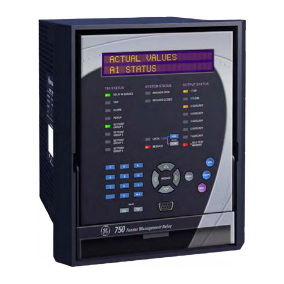
Page 73: Front Panel
The display and status indicators update alarm and status information automati- cally. The control keys are used to select the appropriate message for entering setpoints or displaying measured values. The RS232 program port is also provided for connection with a computer running the 750/ 760 PC program. -
Page 74: Status Indicators
5.2 STATUS INDICATORS 5.2.1 DESCRIPTION The front panel indicators are grouped into three columns. The 750/760 STATUS column indicates the state of the relay, the SYSTEM STATUS column indicates the state of the breaker and the system, and the OUTPUT STATUS column indicates the state of the output relays. -
Page 75: Output Status Indicators
5.2.4 OUTPUT STATUS INDICATORS The 750 and 760 have eight output relays. 1 TRIP, 2 CLOSE, and 8 SELF-TEST WARNING have fixed opera- tion while 3-7 AUXILIARY are configurable. Regardless of the mode of operation, the corresponding front panel indicator turns on while the output relay is signaling. -
Page 76: Keypad Operation
5 FRONT PANEL OPERATION 5.3 KEYPAD OPERATION 5.3.1 DESCRIPTION The 750/760 display messages are organized into pages under the headings Setpoints and Actual Values. The key navigates through the page headers of programmable parameters (Setpoints). The key nav- A C T U A L igates through the page headers of measured parameters (Actual Values). -
Page 77: Messages
Record the failure in the EVENT RECORDER. Upon detection of a major problem, the relay will (if possible) also: • Turn off the RELAY IN SERVICE indicator. • Inhibit operation of all output relays GE Power Management 750/760 Feeder Management Relay Courtesy of NationalSwitchgear.com... -
Page 78: Description
This warning is caused by a failure of the Real Time Clock circuit. The ability of the relay to maintain the current date and time is lost. Simulation Mode Minor This warning occurs when the simulation feature of the relay is active. 750/760 Feeder Management Relay GE Power Management Courtesy of NationalSwitchgear.com... -
Page 79: Flash Messages
This flash message is displayed in response to the key while the NO CONDITIONS ARE N E X T MESSAGE indicator is off. There are no active conditions to display in the CURRENTLY ACTIVE diagnostic message queue. GE Power Management 750/760 Feeder Management Relay Courtesy of NationalSwitchgear.com... - Page 80 IS NOW RESTRICTED S1 RELAY SETUP \ PASSCODE \ RESTRICT . The command to restrict access to setpoints has ACCESS TO SETPOINTS? been successfully executed and setpoints cannot be changed. 750/760 Feeder Management Relay GE Power Management Courtesy of NationalSwitchgear.com...
-
Page 81: Actual Values
1. Front panel, using the keys and display. 2. Front program port, and a portable computer running the 750/760 PC program supplied with the relay. 3. Rear RS485/RS422 COM 1 port or RS485 COM 2 port with a SCADA system running user written soft- ware. - Page 82 6.1 OVERVIEW 6 ACTUAL VALUES Figure 6–1: ACTUAL VALUES BLOCK DIAGRAM (1 OF 2) 750/760 Feeder Management Relay GE Power Management Courtesy of NationalSwitchgear.com...
- Page 83 6 ACTUAL VALUES 6.1 OVERVIEW Figure 6–2: ACTUAL VALUES BLOCK DIAGRAM (2 OF 2) GE Power Management 750/760 Feeder Management Relay Courtesy of NationalSwitchgear.com...
-
Page 84: A1 Status
Coil Monitor 2 input. Note: the name programmed under STATE: Open S6 MONITORING \ EQUIP- will be displayed on the top line. MENT \ COIL 2 MONITOR \ COIL 2 MONITOR NAME 750/760 Feeder Management Relay GE Power Management Courtesy of NationalSwitchgear.com... -
Page 85: Last Trip Data
This message displays the value of the system frequency at the moment of the SYSTEM FREQUENCY: event. 0.00 Hz This message displays the value of the analog input current at the moment of ANALOG INPUT 0 µA the event. GE Power Management 750/760 Feeder Management Relay Courtesy of NationalSwitchgear.com... -
Page 86: Fault Locations
The current date is displayed. If the date has never been programmed, this CURRENT DATE: message will display “Unavailable”. November 23 1998 The current time is displayed. If the time has never been programmed, the CURRENT TIME: message will display “Unavailable”. 16:30:00 750/760 Feeder Management Relay GE Power Management Courtesy of NationalSwitchgear.com... -
Page 87: Autoreclose (760 Only)
This message displays the last date the Autoreclose counter data was cleared. AR SHOT COUNT LAST If the date has never been programmed, this message will display “Unavail- RESET: Oct 25 1998 able.” GE Power Management 750/760 Feeder Management Relay Courtesy of NationalSwitchgear.com... -
Page 88: A2 Metering
SENSTV GND CURRENT: 0.00 A 0° Lag Displays the calculated positive sequence current RMS phasor. POS SEQ CURRENT: 0° Lag ----------------------------------- - for ABC phase sequence for ACB phase sequence ----------------------------------- - 750/760 Feeder Management Relay GE Power Management Courtesy of NationalSwitchgear.com... -
Page 89: Voltage
0° Lag Displays the measured B-N RMS voltage phasor PHASE B-N VOLTAGE: 0.00 kV 0° Lag Displays the measured C-N RMS voltage phasor PHASE C-N VOLTAGE: 0.00 kV 0° Lag GE Power Management 750/760 Feeder Management Relay Courtesy of NationalSwitchgear.com... -
Page 90: Frequency
0.00 Hz Displays the differences of phase position, voltage magnitude, and frequency SYNCHRO DELTA: 0° between the line VT input and its corresponding bus VT input 0.00 kV 0.00 Hz 750/760 Feeder Management Relay GE Power Management Courtesy of NationalSwitchgear.com... -
Page 91: Power
B and C. 0.0 MVA ΦA POWER FACTOR: This message displays phase A power factor as leading or lagging. Similar power messages appear for phase B and C. 0.00 GE Power Management 750/760 Feeder Management Relay Courtesy of NationalSwitchgear.com... - Page 92 - Var PF=Lag PF=Lead Bus Voltage E S4=E + Watt - Watt + Var + Var PF=Lead PF=Lag = Angle By Which Voltage Leads Current 818773AC.CDR Figure 6–3: POWER QUANTITY RELATIONSHIPS 750/760 Feeder Management Relay GE Power Management Courtesy of NationalSwitchgear.com...
-
Page 93: Energy
SETUP \ POWER SYSTEM \ COST OF ENERGY provide approximate costs. Energy quantities auto-range to show units appropriate to the nominal power. NOTE: The 750/760 is not a revenue class meter and cannot be used for billing purposes. The Energy actual values path is:... -
Page 94: Demand
This message displays the last date the maximum demand data was cleared. DEMAND DATA LAST If the date has never been programmed, this relay will display ‘Unavailable’. RESET: Mar 16 1997 750/760 Feeder Management Relay GE Power Management Courtesy of NationalSwitchgear.com... -
Page 95: Analog Input
This message displays the analog input rate of change per minute. ANALOG INPUT: 0 µA /min This message displays the analog input rate of change per hour. ANALOG INPUT: 0 µA /hour GE Power Management 750/760 Feeder Management Relay Courtesy of NationalSwitchgear.com... -
Page 96: A3 Maintenance
This message displays the last date the trip counter data was cleared. If the TRIP COUNTERS LAST date has never been programmed, this message will display ‘Unavailable’. RESET: Mar 16 1997 750/760 Feeder Management Relay GE Power Management Courtesy of NationalSwitchgear.com... -
Page 97: Arcing Current
This message displays the last date the total arcing current data was cleared. ARCING CURRENT LAST If the date has never been programmed, the relay will display ‘Unavailable’. RESET: Mar 16 1997 GE Power Management 750/760 Feeder Management Relay Courtesy of NationalSwitchgear.com... -
Page 98: A4 Event Recorder
6.5 A4 EVENT RECORDER 6.5.1 DESCRIPTION The 750/760 has an event recorder which runs continuously, capturing and storing the last 128 events. All event recorder information is stored in non-volatile memory so the information is maintained after losing relay control power. -
Page 99: Last Reset Date
[ENTER] for more \ ACTUAL VALUES \ A4 EVENT RECORDER \ LAST RESET DATE Displays the date the event recorder was last cleared EVENT RECORDER LAST RESET: Mar 16 1997 GE Power Management 750/760 Feeder Management Relay Courtesy of NationalSwitchgear.com... -
Page 100: Event Types
Self-Test Warning Events SELF-TEST WARNING < Cause > These are events that occur when a self-test warning is detected or one of the manual testing features is enabled. 750/760 Feeder Management Relay GE Power Management Courtesy of NationalSwitchgear.com... -
Page 101: A General Event Causes
Cold Load P/U Block * For user inputs A -T the user defined name is displayed. ** The pulse output quantity name is displayed. *** The coil monitor name is displayed. GE Power Management 750/760 Feeder Management Relay Courtesy of NationalSwitchgear.com... -
Page 102: Setpoints
Force Analog Out EEPROM Corrupt Clock Not Set Not Calibrated Simulation Mode FLASH Corrupt Prototype Software RTC Crystal Pickup Test Factory Service Internal RS485 IRIG-B Failure Analog Output +32V Internal Temp 750/760 Feeder Management Relay GE Power Management Courtesy of NationalSwitchgear.com... -
Page 103: A5 Product Info
This page specifies product information including hardware revision and configuration, software revision, and serial number. Also included are the manufacturing and calibration dates. This information is intended for GE Power Management service personnel. It also has information on where to obtain Technical Support. -
Page 104: Calibration Dates
This message displays the date the relay was calibrated at the factory. FACTORY CALIBRATION DATE: Oct 25 1997 This message displays the date calibration parameters were last modified. LAST CALIBRATION DATE: Oct 25 1997 750/760 Feeder Management Relay GE Power Management Courtesy of NationalSwitchgear.com... -
Page 105: Setpoints
7 SETPOINTS 7.1 OVERVIEW 7.1.1 MESSAGE SUMMARY The 750/760 has a considerable number of programmable setpoints which makes it extremely flexible. The setpoints have been grouped into a number of pages and sub-pages as shown below. Each page of setpoints (e.g. -
Page 106: Setpoint Entry Methods
1. Front panel, using the keys and display. 2. Front program port, and a portable computer running the 750/760 PC program supplied with the relay. 3. Rear RS485/RS422 COM1 port or RS485 COM2 port and a SCADA system running user-written software. -
Page 107: Setpoint Access Security
The 750/760 PC Program, included with the relay, incorporates a facility for programming the relay’s passcode as well as enabling/disabling setpoint access. For example, when an attempt is made to modify a setpoint but access is restricted, the program will prompt the user to enter the passcode and send it to the relay before the setpoint is actually written to the relay. -
Page 108: Common Setpoints
1 TRIP relay, the total delay is the time selected in this setpoint plus approximately 2.5 power frequency periods. In both cases, auxiliary output relays are approximately 5 ms slower. 750/760 Feeder Management Relay GE Power Management Courtesy of NationalSwitchgear.com... -
Page 109: Setpoints
If Setting = Any Two : an output is generated if any combination of two or more phase parameters are beyond the pickup setting. If Setting = All Three : an output is generated if all three phase parameters are beyond the pickup setting. GE Power Management 750/760 Feeder Management Relay Courtesy of NationalSwitchgear.com... -
Page 110: Logic Diagrams
Conditions are mutually exclusive, i.e., only one condition can be active at any point in time. • Conditions latch until another condition becomes active. • The output of an active condition is 1 or logic high. 750/760 Feeder Management Relay GE Power Management Courtesy of NationalSwitchgear.com... -
Page 111: S1 Relay Setup
Range: (Cannot Be Edited) ENCRYPTED PASSCODE: AIKFBAIK If the programmed passcode is not known, consult the factory service depart- ment with the 8 character word displayed. GE Power Management 750/760 Feeder Management Relay Courtesy of NationalSwitchgear.com... -
Page 112: Communications
Selects the baud rate for front panel RS232 serial communications port. When upgrading the relay firmware, this rate should be set to 9600 Baud. Range: None, Odd, Even FRONT RS232 PARITY: None Selects the parity for the front RS232 port. 750/760 Feeder Management Relay GE Power Management Courtesy of NationalSwitchgear.com... -
Page 113: Dnp Communications
WRITE TIME INTERVAL: 0 min Select the time that must elapse before the 750/760 will set the “need time” internal indication (IIN). After the time is written by a DNP master, the IIN will be set again after this time elapses. A value of zero disables this feature. -
Page 114: Clock
(except for the year) as described in the previous message will have no effect. 3. If IRIG-B is enabled but the signal cannot be decoded, the self-test warn- ing ‘IRIG-B Failure’ is generated. 750/760 Feeder Management Relay GE Power Management Courtesy of NationalSwitchgear.com... -
Page 115: Event Recorder
Enter Disabled for this setpoint to inhibit recording of logic input events. Range: Enabled, Disabled RECORD DATE/TIME EVENTS: Enabled Enter Disabled for this setpoint to inhibit recording of set date and set time events. GE Power Management 750/760 Feeder Management Relay Courtesy of NationalSwitchgear.com... -
Page 116: Trace Memory
) as well as digital data for the output relays and input contact states. The trace memory data can be downloaded to the 750/760 PC Program for display and diagnostics purposes. All data is stored in volatile RAM memory which means that the information is lost when power to the relay is lost. The amount of data to capture and the trigger point are configurable as described below. -
Page 117: Data Logger
The data logger feature is used to sample and record up to eight actual values at an interval that is defined by the user. This recorded data may be downloaded to the 750/760 PC Program for display and diagnostics. All data is stored in volatile RAM memory which means that the information is lost when power to the relay is lost. - Page 118 Range: Any Value that may be Assigned as an Analog Output Function CHANNEL 8 SOURCE: Frequency Select the actual value that is to be recorded in channel 8 of the data log. 750/760 Feeder Management Relay GE Power Management Courtesy of NationalSwitchgear.com...
-
Page 119: Front Panel
Max Demand Values. Firmware versions 3.70 and greater do not support a keypad beeper as did previous firmware versions. The PC software does not support keypad beeper operation. NOTE GE Power Management 750/760 Feeder Management Relay Courtesy of NationalSwitchgear.com... -
Page 120: Default Messages
The message is now removed E N T E R from the default message list, and the messages that follow are moved up to fill the gap. 750/760 Feeder Management Relay GE Power Management Courtesy of NationalSwitchgear.com... -
Page 121: User Text Messages
E N T E R 7. Press the key when editing is complete. To select this message as a default mes- sage, follow the instructions in the section on adding default messages. GE Power Management 750/760 Feeder Management Relay Courtesy of NationalSwitchgear.com... -
Page 122: Clear Data
Enter Yes to clear all recorded event data in actual values page . The date is updated to A4 EVENT RECORDER EVENT RECORDER LAST RESET the current date upon issuing this command. 750/760 Feeder Management Relay GE Power Management Courtesy of NationalSwitchgear.com... -
Page 123: Installation
Range Yes, No RESET AR RATE DATA? No Enter Yes to clear the Autoreclose Shot Rate under the actual values subgroup A1 STATUS \ AUTORECLOSE GE Power Management 750/760 Feeder Management Relay Courtesy of NationalSwitchgear.com... - Page 124 8.12 INSTALLATION 8 S1 RELAY SETUP 750/760 Feeder Management Relay GE Power Management Courtesy of NationalSwitchgear.com...
-
Page 125: S2 System Setup
Enter the sensitive ground CT primary current value. For both 1000:5 or 1000:1 CTs, the entry would be 1000 . Verify that the CT secondary rating matches the rating on the relay label. GE Power Management 750/760 Feeder Management Relay Courtesy of NationalSwitchgear.com... -
Page 126: Bus Vt Sensing
Range: 1.0 to 5000.0 in steps of 0.1 VT RATIO: 120.0:1 Enter the VT primary to secondary turns ratio with this setpoint. For a 14400:120 VT, the entry would be 120:1 (14400 / 120 = 120.0). 750/760 Feeder Management Relay GE Power Management Courtesy of NationalSwitchgear.com... -
Page 127: Line Vt Sensing
Range: 1.0 to 5000.0 in steps of 0.1 VT RATIO: 120.0:1 Enter the VT primary to secondary turns ratio with this setpoint. For a 14400:120 VT, the entry would be 120.0:1 (14400 / 120 = 120.0). GE Power Management 750/760 Feeder Management Relay Courtesy of NationalSwitchgear.com... -
Page 128: Power System
Enter an estimated average cost in cents per kWh. Approximate energy cost will be determined by the relay, pro- viding a value useful for budgeting purposes. 750/760 Feeder Management Relay GE Power Management Courtesy of NationalSwitchgear.com... -
Page 129: Flexcurves
The following table shows all the pickup levels for which a trip time must be entered. GE Power Management 750/760 Feeder Management Relay Courtesy of NationalSwitchgear.com... - Page 130 6.50 16.5 2.20 4.20 7.00 17.0 2.30 4.30 7.50 17.5 2.40 4.40 8.00 18.0 2.50 4.50 8.50 18.5 2.60 4.60 9.00 19.0 2.70 4.70 9.50 19.5 2.80 4.80 10.0 20.0 750/760 Feeder Management Relay GE Power Management Courtesy of NationalSwitchgear.com...
-
Page 131: S3 Logic Inputs
10 S3 LOGIC INPUTS 10.1 OVERVIEW 10.1.1 INTRODUCTION The 750/760 relay has 20 logic inputs which can be used to operate a variety of logic functions for circuit breaker control, external trips, blocking of protection elements, etc. The relay has ‘contact inputs’ and ‘virtual inputs’... -
Page 132: Description
Y ASSERTED LOGIC • A logic function is invoked when its corresponding logic input is ASSERTED. • One logic input can invoke many logic functions if required. 750/760 Feeder Management Relay GE Power Management Courtesy of NationalSwitchgear.com... -
Page 133: Settings
For logic inputs 15 to 20 the setpoint has the following choices: SETPOINT VALUE LOGIC INPUT ASSERTED WHEN: Disabled Never Virtual On Virtual Input is On Virtual Off Virtual Input is Off GE Power Management 750/760 Feeder Management Relay Courtesy of NationalSwitchgear.com... -
Page 134: Description
52b closed indicates breaker is open Breaker status unknown For further information regarding operation with only one auxiliary breaker contact, see Section 5.2.3: SYS- TEM STATUS INDICATORS on page 5–2. 750/760 Feeder Management Relay GE Power Management Courtesy of NationalSwitchgear.com... -
Page 135: Settings
Signals setpoint control to make Group 3 the active group. Range: Disabled, Input 1, Input 2, ..., Input 20 SETPOINT GROUP 4: Disabled Signals setpoint control to make Group 4 the active group. GE Power Management 750/760 Feeder Management Relay Courtesy of NationalSwitchgear.com... -
Page 136: Description
Range: 0.00 to 600.00 in steps of 0.01 s USER INPUT A DELAY: 0.00 s Selects the amount of time that the logic input must remain asserted before User Input A operates. 750/760 Feeder Management Relay GE Power Management Courtesy of NationalSwitchgear.com... -
Page 137: Description
Range: Disabled, Input 1, Input 2, ..., Input 20 BYPASS SYNCHROCHECK: Disabled Provides a manual override of the synchrocheck monitor, so an operator can close the feeder breaker without the programmed synchrocheck condition. GE Power Management 750/760 Feeder Management Relay Courtesy of NationalSwitchgear.com... - Page 138 BLK NTR DISPLACEMNT: Disabled Blocks the neutral displacement element from operating. Range: Disabled, Input 1, Input 2, ..., Input 20 BLOCK RESTORATION: Disabled Blocks both undervoltage and underfrequency restoration features. 750/760 Feeder Management Relay GE Power Management Courtesy of NationalSwitchgear.com...
-
Page 139: Block Overcurrent Functions
BLOCK NEUTRL TIME 2: Disabled Blocks the neutral time overcurrent 2 element. Range: Disabled, Input 1, Input 2, ..., Input 20 BLOCK NEUTRL INST 1: Disabled Blocks the neutral instantaneous 1 overcurrent element. GE Power Management 750/760 Feeder Management Relay Courtesy of NationalSwitchgear.com... - Page 140 BLOCK NEG SEQ TIME: Disabled Blocks the negative sequence time overcurrent element. Range: Disabled, Input 1, Input 2, ..., Input 20 BLOCK NEG SEQ INST: Disabled Blocks the negative sequence instantaneous overcurrent element. 750/760 Feeder Management Relay GE Power Management Courtesy of NationalSwitchgear.com...
-
Page 141: Transfer Functions
Used to signal the bus tie breaker to begin a close operation. Range: Disabled, Input 1, Input 2, ..., Input 20 CLOSE FROM INCOMER2: DECAY: Disabled Used to signal the bus tie breaker to begin a close operation. GE Power Management 750/760 Feeder Management Relay Courtesy of NationalSwitchgear.com... -
Page 142: Autoreclose Functions (760 Only)
Cancels a reclosure sequence in progress and blocks the autoreclose scheme from operating. Range: Disabled, Input 1, Input 2, ..., Input 20 BLOCK RECLOSURE: Disabled Cancels a reclosure sequence in progress and blocks the autoreclose scheme from operating. 750/760 Feeder Management Relay GE Power Management Courtesy of NationalSwitchgear.com... -
Page 143: Settings
‘fault’ values are used. Range: Disabled, Input 1, Input 2, ..., Input 20 START DEMAND INTERVAL: Disabled This input begins the new demand interval for all Block Interval demand calcu- lations. GE Power Management 750/760 Feeder Management Relay Courtesy of NationalSwitchgear.com... - Page 144 10.10 MISCELLANEOUS FUNCTIONS 10 S3 LOGIC INPUTS 750/760 Feeder Management Relay GE Power Management Courtesy of NationalSwitchgear.com...
-
Page 145: Overview
11 S4 OUTPUT RELAYS 11.1 OVERVIEW 11.1.1 DESCRIPTION The 750/760 relay is equipped with eight electromechanical output relays: three special purpose (1 TRIP, 2 CLOSE, and 8 SELF-TEST WARNING) and five general purpose (3, 4, 5, 6, and 7 AUXILIARY). The special purpose relays have fixed operating characteristics and the general purpose relays can be configured by the user. -
Page 146: Trip And 2 Close Relays
2 CLOSE relay, thus extending its pulse width. This is for use in applications where the 52 contacts report- ing breaker state to the 750/760 are faster than the 52 contacts that are responsible for interrupting coil cur- rent. - Page 147 11 S4 OUTPUT RELAYS 11.2 1 TRIP AND 2 CLOSE RELAYS Figure 11–1: OUTPUT RELAY 1 TRIP GE Power Management 750/760 Feeder Management Relay Courtesy of NationalSwitchgear.com...
- Page 148 11.2 1 TRIP AND 2 CLOSE RELAYS 11 S4 OUTPUT RELAYS Figure 11–2: OUTPUT RELAY 2 CLOSE 750/760 Feeder Management Relay GE Power Management Courtesy of NationalSwitchgear.com...
-
Page 149: Settings
This message is only displayed if the is selected as RELAY 3 OUTPUT TYPE Pulsed . This setpoint determines the time interval that the pulsed contacts remain in the operated state. GE Power Management 750/760 Feeder Management Relay Courtesy of NationalSwitchgear.com... - Page 150 11.3 OUTPUT RELAYS 3-7 AUXILIARY 11 S4 OUTPUT RELAYS Figure 11–3: OUTPUT RELAYS 3-7 AUXILIARY 750/760 Feeder Management Relay GE Power Management Courtesy of NationalSwitchgear.com...
- Page 151 11 S4 OUTPUT RELAYS 11.3 OUTPUT RELAYS 3-7 AUXILIARY Figure 11–4: OUTPUT RELAY 8 SELF-TEST WARNING GE Power Management 750/760 Feeder Management Relay Courtesy of NationalSwitchgear.com...
- Page 152 11.3 OUTPUT RELAYS 3-7 AUXILIARY 11 S4 OUTPUT RELAYS 750/760 Feeder Management Relay GE Power Management Courtesy of NationalSwitchgear.com...
-
Page 153: Time Overcurrent Curve Characteristics
10 are 10 times the multiplier 1 or base curve val- ues. Setting the multiplier to zero results in an instantaneous response to all current levels above pickup. GE Power Management 750/760 Feeder Management Relay Courtesy of NationalSwitchgear.com... -
Page 154: Definite Time Curve
The base Definite Time curve has a delay of 0.1 seconds. The curve multiplier makes this delay adjust- able from 0.00 to 10.00 seconds in steps of 0.01 seconds. 750/760 Feeder Management Relay GE Power Management Courtesy of NationalSwitchgear.com... -
Page 155: Ansi Curves
12.1.3 ANSI CURVES The ANSI time overcurrent curve shapes conform to industry standard curves and fit into the ANSI C37.90 curve classifications for extremely, very, normally, and moderately inverse. The 750/760 curves are derived from the formula: where T = Trip Time (seconds) ... -
Page 156: Iac Curves
0.569 0.542 0.524 0.511 0.501 0.493 Graphs of standard time-current curves on 11” × 17” log-log graph paper are available upon request. Requests may be placed with our literature department. 750/760 Feeder Management Relay GE Power Management Courtesy of NationalSwitchgear.com... -
Page 157: Iec Curves
0.752 0.673 0.618 0.576 0.544 0.518 Graphs of standard time-current curves on 11” × 17” log-log graph paper are available upon request. Requests may be placed with our literature department. GE Power Management 750/760 Feeder Management Relay Courtesy of NationalSwitchgear.com... -
Page 158: Directional Overcurrent Characteristics
The following diagram specifically shows the phasors involved for phase A directional polarization, but the gen- eral principles can be applied to all directional elements. Figure 12–1: PHASE A DIRECTIONAL OVERCURRENT POLARIZING 750/760 Feeder Management Relay GE Power Management Courtesy of NationalSwitchgear.com... -
Page 159: Phase Overcurrent
If the BUS INPUT VT TYPE selected to None , this feature is automatically disabled. GE Power Management 750/760 Feeder Management Relay Courtesy of NationalSwitchgear.com... - Page 160 If voltage restraint is enabled, the adjusted pickup, calculated by adjusting the pickup value by the multiplier, will not fall below 0.05 × CT, which is the lowest setting for the PHASE TIME OC PICKUP. NOTE 750/760 Feeder Management Relay GE Power Management Courtesy of NationalSwitchgear.com...
- Page 161 12 S5 PROTECTION 12.2 DIRECTIONAL OVERCURRENT CHARACTERISTICS Figure 12–3: PHASE TIME OVERCURRENT LOGIC DIAGRAM (1 OF 2) GE Power Management 750/760 Feeder Management Relay Courtesy of NationalSwitchgear.com...
- Page 162 12.2 DIRECTIONAL OVERCURRENT CHARACTERISTICS 12 S5 PROTECTION Figure 12–4: PHASE TIME OVERCURRENT LOGIC DIAGRAM (2 OF 2) 750/760 Feeder Management Relay GE Power Management Courtesy of NationalSwitchgear.com...
-
Page 163: Phase Instantaneous Overcurrent
OPERATION: Any One Select the type of operation required. Range: Disabled, Forward, Reverse PHASE INST OC 1 DIRECTION: Disabled Select the direction(s) of current flow for which operation is permitted. GE Power Management 750/760 Feeder Management Relay Courtesy of NationalSwitchgear.com... - Page 164 12.2 DIRECTIONAL OVERCURRENT CHARACTERISTICS 12 S5 PROTECTION Figure 12–5: PHASE INSTANTANEOUS OVERCURRENT LOGIC DIAGRAM 750/760 Feeder Management Relay GE Power Management Courtesy of NationalSwitchgear.com...
-
Page 165: Phase Directional
12.2 DIRECTIONAL OVERCURRENT CHARACTERISTICS 12.2.5 PHASE DIRECTIONAL The 750/760 uses the secure 90° or quadrature connection exclusively for phase directional polarization. An MTA setting of 90° represents a phase current in-phase with its phase voltage, which is leading the polarizing voltage by 90°. -
Page 166: Phase Directional Setpoints
Disabled , all phase overcurrent elements will not be inhibited by directional control. This setpoint also determines the operation of the phase overcurrent elements under directional control upon ‘Close Into Fault’ (CIF). 750/760 Feeder Management Relay GE Power Management Courtesy of NationalSwitchgear.com... - Page 167 12 S5 PROTECTION 12.2 DIRECTIONAL OVERCURRENT CHARACTERISTICS Figure 12–6: PHASE DIRECTIONAL LOGIC DIAGRAM GE Power Management 750/760 Feeder Management Relay Courtesy of NationalSwitchgear.com...
-
Page 168: Neutral Overcurrent
See description in Section 12.1: TIME OVERCURRENT CURVE CHARAC- TERISTICS on page 12–1. Range: Disabled, Forward, Reverse NEUTRAL TIME OC 1 DIRECTION: Disabled Select the direction(s) of current flow for which operation is permitted. 750/760 Feeder Management Relay GE Power Management Courtesy of NationalSwitchgear.com... - Page 169 12 S5 PROTECTION 12.3 NEUTRAL OVERCURRENT Figure 12–7: NEUTRAL TIME OVERCURRENT LOGIC DIAGRAM GE Power Management 750/760 Feeder Management Relay Courtesy of NationalSwitchgear.com...
-
Page 170: Neutral Instantaneous Overcurrent
NEUTRAL INST OC 1 DELAY: 0.00 s Select the delay required. Range: Disabled, Forward, Reverse NEUTRAL INST OC 1 DIRECTION: Disabled Select the direction(s) of current flow for which operation is permitted. 750/760 Feeder Management Relay GE Power Management Courtesy of NationalSwitchgear.com... - Page 171 12 S5 PROTECTION 12.3 NEUTRAL OVERCURRENT Figure 12–8: NEUTRAL INSTANTANEOUS OVERCURRENT LOGIC DIAGRAM GE Power Management 750/760 Feeder Management Relay Courtesy of NationalSwitchgear.com...
-
Page 172: Neutral Directional
If the polarizing current magnitude is insufficient then the voltage polariz- ing takes control. If neither voltage nor current polarizing is possible then the direction defaults to forward. Figure 12–9: NEUTRAL DIRECT VOLTAGE POLARIZING 750/760 Feeder Management Relay GE Power Management Courtesy of NationalSwitchgear.com... - Page 173 2% of VT nominal voltage. For systems with high-resistance grounding or floating neutrals, this setpoint can be as high as 20%. The default value of 0.05 x VT is appropriate for most solidly grounded systems. GE Power Management 750/760 Feeder Management Relay Courtesy of NationalSwitchgear.com...
- Page 174 12.3 NEUTRAL OVERCURRENT 12 S5 PROTECTION Figure 12–10: NEUTRAL DIRECTIONAL LOGIC DIAGRAM 750/760 Feeder Management Relay GE Power Management Courtesy of NationalSwitchgear.com...
-
Page 175: Ground Overcurrent
See description in Section 12.1: TIME OVERCURRENT CURVE CHARAC- TERISTICS on page 12–1. Range: Disabled, Forward, Reverse GROUND TIME OC DIRECTION: Disabled Select the direction(s) of current flow for which operation is permitted. GE Power Management 750/760 Feeder Management Relay Courtesy of NationalSwitchgear.com... - Page 176 12.4 GROUND OVERCURRENT 12 S5 PROTECTION Figure 12–11: GROUND TIME OVERCURRENT LOGIC DIAGRAM 750/760 Feeder Management Relay GE Power Management Courtesy of NationalSwitchgear.com...
-
Page 177: Ground Instantaneous Overcurrent
GROUND INST OC DELAY: 0.00 s Select the delay required. Range: Disabled, Forward, Reverse GROUND INST OC DIRECTION: Disabled Select the direction(s) of current flow for which operation is permitted. GE Power Management 750/760 Feeder Management Relay Courtesy of NationalSwitchgear.com... - Page 178 12.4 GROUND OVERCURRENT 12 S5 PROTECTION Figure 12–12: GROUND INSTANTANEOUS OVERCURRENT LOGIC DIAGRAM 750/760 Feeder Management Relay GE Power Management Courtesy of NationalSwitchgear.com...
-
Page 179: Ground Directional
If the polarizing current magnitude is insufficient then the voltage polarizing takes control. If neither voltage nor current polarizing is possible then the direction defaults to for- ward. GE Power Management 750/760 Feeder Management Relay Courtesy of NationalSwitchgear.com... -
Page 180: Ground Directional Setpoints
2% of VT nominal voltage. For systems with high-resistance grounding or floating neutrals, this setpoint can be as high as 20%. The default value of 0.05 x VT is appropriate for most solidly grounded systems. 750/760 Feeder Management Relay GE Power Management Courtesy of NationalSwitchgear.com... - Page 181 12 S5 PROTECTION 12.4 GROUND OVERCURRENT Figure 12–13: GROUND DIRECTIONAL LOGIC DIAGRAM GE Power Management 750/760 Feeder Management Relay Courtesy of NationalSwitchgear.com...
-
Page 182: Description
See description in Section 12.1: TIME OVERCURRENT CURVE CHARAC- TERISTICS on page 12–1. Range: Disabled, Forward, Reverse SENSTV GND TIME OC DIRECTION: Disabled Select the direction(s) of current flow for which operation is permitted. 750/760 Feeder Management Relay GE Power Management Courtesy of NationalSwitchgear.com... - Page 183 12 S5 PROTECTION 12.5 SENSITIVE GROUND CURRENT Figure 12–14: SENSITIVE GROUND TIME OVERCURRENT LOGIC DIAGRAM GE Power Management 750/760 Feeder Management Relay Courtesy of NationalSwitchgear.com...
-
Page 184: Sensitive Ground Instantaneous Overcurrent
SENSTV GND INST OC DELAY: 0.00 s Select the delay required. Range: Disabled, Forward, Reverse SENSTV GND INST OC DIRECTION: Disabled Select the direction(s) of current flow for which operation is permitted. 750/760 Feeder Management Relay GE Power Management Courtesy of NationalSwitchgear.com... - Page 185 12 S5 PROTECTION 12.5 SENSITIVE GROUND CURRENT Figure 12–15: SENSITIVE GROUND INSTANTANEOUS OVERCURRENT LOGIC DIAGRAM GE Power Management 750/760 Feeder Management Relay Courtesy of NationalSwitchgear.com...
-
Page 186: Sensitive Ground Directional
If the polarizing current magnitude is insufficient then the voltage polarizing takes control. If neither voltage nor current polarizing is possible then the direction defaults to for- ward. 750/760 Feeder Management Relay GE Power Management Courtesy of NationalSwitchgear.com... -
Page 187: Sensitive Ground Directional Setpoints
2% of VT nominal voltage. For systems with high-resistance grounding or floating neutrals, this setpoint can be as high as 20%. The default value of 0.05 x VT is appropriate for most solidly grounded systems. GE Power Management 750/760 Feeder Management Relay Courtesy of NationalSwitchgear.com... - Page 188 12.5 SENSITIVE GROUND CURRENT 12 S5 PROTECTION Figure 12–16: SENSITIVE GROUND DIRECTIONAL CURRENT 750/760 Feeder Management Relay GE Power Management Courtesy of NationalSwitchgear.com...
-
Page 189: Restricted Earth Fault
Although the 750/760 is designed for feeder protection, it can provide Restricted Earth Fault protection on transformers that do not have dedicated protection. To use the 750/760 for this type of protection, a stabilizing resistor and possibly a non-linear resistor will be required. -
Page 190: C Sample Application
0.962 A -------------------- - 13.74 A Smax 0.07 ratio of 2 is assumed to ensure operation. + 2 R ) = 77.05 V = 2 V = 154.1 V 750/760 Feeder Management Relay GE Power Management Courtesy of NationalSwitchgear.com... -
Page 191: D Calculating The Stabilizing Resistor
PICKUP: 0.100 x CT Enter the pickup in terms of the CT rating. Range: 0.00 to 600.00 in steps of 0.01 s RESTRICTED EARTH FLT DELAY: 0.00 s Select the delay required. GE Power Management 750/760 Feeder Management Relay Courtesy of NationalSwitchgear.com... - Page 192 12.5 SENSITIVE GROUND CURRENT 12 S5 PROTECTION Figure 12–18: RESTRICTED EARTH FAULT LOGIC DIAGRAM 750/760 Feeder Management Relay GE Power Management Courtesy of NationalSwitchgear.com...
-
Page 193: Description
See description in Section 12.1: TIME OVERCURRENT CURVE CHARAC- TERISTICS on page 12–1. Range: Disabled, Forward, Reverse NEG SEQ TIME OC DIRECTION: Disabled Select the direction(s) of current flow for which operation is permitted. GE Power Management 750/760 Feeder Management Relay Courtesy of NationalSwitchgear.com... - Page 194 12.6 NEGATIVE SEQUENCE 12 S5 PROTECTION Figure 12–19: NEGATIVE SEQUENCE TIME OVERCURRENT LOGIC DIAGRAM 750/760 Feeder Management Relay GE Power Management Courtesy of NationalSwitchgear.com...
-
Page 195: Negative Sequence Instantaneous Overcurrent
NEG SEQ INST OC DELAY: 0.00 s Select the delay required. Range: Disabled, Forward, Reverse NEG SEQ INST OC DIRECTION: Disabled Select the direction(s) of current flow for which operation is permitted. GE Power Management 750/760 Feeder Management Relay Courtesy of NationalSwitchgear.com... - Page 196 12.6 NEGATIVE SEQUENCE 12 S5 PROTECTION Figure 12–20: NEGATIVE SEQUENCE INSTANTANEOUS OVERCURRENT LOGIC DIAGRAM 750/760 Feeder Management Relay GE Power Management Courtesy of NationalSwitchgear.com...
-
Page 197: Negative Sequence Directional
For systems with high-resistance grounding or floating neutrals, this setpoint can be as high as 20%. The default value of 0.05 x VT is appropri- ate for most solidly grounded systems. GE Power Management 750/760 Feeder Management Relay Courtesy of NationalSwitchgear.com... - Page 198 12.6 NEGATIVE SEQUENCE 12 S5 PROTECTION Figure 12–21: NEGATIVE SEQUENCE DIRECTIONAL LOGIC DIAGRAM 750/760 Feeder Management Relay GE Power Management Courtesy of NationalSwitchgear.com...
-
Page 199: Negative Sequence Voltage
Enter the pickup as a fraction of the bus VT nominal voltage. Range: 0.0 to 6000.0 in steps of 0.1 s NEG SEQ VOLTAGE DELAY: 2.0 s Select the delay required. GE Power Management 750/760 Feeder Management Relay Courtesy of NationalSwitchgear.com... - Page 200 12.6 NEGATIVE SEQUENCE 12 S5 PROTECTION Figure 12–22: NEGATIVE SEQUENCE VOLTAGE LOGIC DIAGRAM 750/760 Feeder Management Relay GE Power Management Courtesy of NationalSwitchgear.com...
-
Page 201: Description
VOLTAGE: 0.30 x VT Inhibits the Bus Undervoltage 1 element for voltages below this level. Setting to 0.00 x VT will allow a dead bus to be considered a fault condition. GE Power Management 750/760 Feeder Management Relay Courtesy of NationalSwitchgear.com... -
Page 202: Undervoltage Inverse Time Delay Characteristics
D = 1.0 D = 5.0 12.0 10.0 D = 1.0 D = 2.0 D = 1.0 D = 1.0 D=1.0 D=2.0 % of Pickup D=5.0 Figure 12–23: INVERSE TIME UNDERVOLTAGE CURVES 750/760 Feeder Management Relay GE Power Management Courtesy of NationalSwitchgear.com... - Page 203 12 S5 PROTECTION 12.7 VOLTAGE Figure 12–24: BUS UNDERVOLTAGE 1 / 2 LOGIC DIAGRAM GE Power Management 750/760 Feeder Management Relay Courtesy of NationalSwitchgear.com...
-
Page 204: Line Undervoltage
VOLTAGE: 0.30 x VT The Line Undervoltage 3 element is inhibited for voltages below this level. Set- ting this voltage to 0.00 will allow a dead bus to be considered a fault condition. 750/760 Feeder Management Relay GE Power Management Courtesy of NationalSwitchgear.com... - Page 205 12 S5 PROTECTION 12.7 VOLTAGE Figure 12–25: LINE UNDERVOLTAGE 3 / 4 LOGIC DIAGRAM GE Power Management 750/760 Feeder Management Relay Courtesy of NationalSwitchgear.com...
-
Page 206: Overvoltage
Range: 0.0 to 6000.0 in steps of 0.1 s OVERVOLTAGE 1 DELAY: 2.0 s Selects the delay required. Range: Any One, Any Two, All Three PHASES REQUIRED FOR OPERATION: All Three Select the type of operation required. 750/760 Feeder Management Relay GE Power Management Courtesy of NationalSwitchgear.com... - Page 207 12 S5 PROTECTION 12.7 VOLTAGE Figure 12–26: OVERVOLTAGE 1 / 2 LOGIC DIAGRAM GE Power Management 750/760 Feeder Management Relay Courtesy of NationalSwitchgear.com...
-
Page 208: Neutral Displacement
12 S5 PROTECTION 12.7.6 NEUTRAL DISPLACEMENT The 750/760 incorporates a Neutral Displacement element, which uses the internally derived 3 V value. This protection element requires the three phase Bus VTs to be wye connected. When setting the pickup level for this element, it is important to consider the error in the VT ratio as well as the normal voltage unbalance on the system. - Page 209 12 S5 PROTECTION 12.7 VOLTAGE Figure 12–27: NEUTRAL DISPLACEMENT SCHEME LOGIC DIAGRAM GE Power Management 750/760 Feeder Management Relay Courtesy of NationalSwitchgear.com...
-
Page 210: Description
12.8 FREQUENCY 12.8.1 DESCRIPTION The 750/760 can be used as the primary detecting relay in automatic load shedding schemes based on under- frequency. The need for such a relay arises if during a system disturbance, an area becomes electrically iso- lated from the main system and suffers a generation deficiency due to the loss of either transmission or generation facilities. - Page 211 12 S5 PROTECTION 12.8 FREQUENCY Figure 12–28: UNDERFREQUENCY 1 / 2 LOGIC DIAGRAM GE Power Management 750/760 Feeder Management Relay Courtesy of NationalSwitchgear.com...
-
Page 212: Frequency Decay
Enter the minimum value of current required on any phase to allow the fre- quency decay element to operate. Used to prevent underfrequency tripping during periods of light load, when this action would have an insignificant effect on the system. 750/760 Feeder Management Relay GE Power Management Courtesy of NationalSwitchgear.com... - Page 213 12 S5 PROTECTION 12.8 FREQUENCY Figure 12–29: FREQUENCY DECAY LOGIC DIAGRAM GE Power Management 750/760 Feeder Management Relay Courtesy of NationalSwitchgear.com...
-
Page 214: Description
BREAKER FAILURE DELAY selected output relays and force the 760 autoreclose scheme to lockout. To provide user flexibility, the 750/760 has included two programmable delays for the BREAKER FAILURE FUNC- . The timers can be used singularly or in combination with each other. The difference between the two is TION their location in the logic diagram. - Page 215 12 S5 PROTECTION 12.9 BREAKER FAILURE Figure 12–30: BREAKER FAILURE LOGIC DIAGRAM GE Power Management 750/760 Feeder Management Relay Courtesy of NationalSwitchgear.com...
- Page 216 12.9 BREAKER FAILURE 12 S5 PROTECTION 750/760 Feeder Management Relay GE Power Management Courtesy of NationalSwitchgear.com...
-
Page 217: Description
Enter the pickup in terms of the CT rating. If 100:5 phase CTs are installed, enter 0.9 x CT for an alarm level of 90 amps. Range: 0 to 60000 in steps of 1 s NEUTRAL CURRENT DELAY: Select the delay required. GE Power Management 750/760 Feeder Management Relay Courtesy of NationalSwitchgear.com... - Page 218 13.1 CURRENT LEVEL 13 S6 MONITORING Figure 13–1: PHASE CURRENT LOGIC DIAGRAM 750/760 Feeder Management Relay GE Power Management Courtesy of NationalSwitchgear.com...
- Page 219 13 S6 MONITORING 13.1 CURRENT LEVEL Figure 13–2: NEUTRAL CURRENT LOGIC DIAGRAM GE Power Management 750/760 Feeder Management Relay Courtesy of NationalSwitchgear.com...
-
Page 220: Description
30% threshold before the timer has timed-out, the element will reset without operating. A loss of voltage during any state will return both to the POWER FACTOR 1 reset state. 750/760 Feeder Management Relay GE Power Management Courtesy of NationalSwitchgear.com... -
Page 221: Setpoints
POWER , the selected output relay(s) will reset. FACTOR 1 DELAY Range: 0 to 60000 in steps of 1 s POWER FACTOR 1 DELAY: 50 s Select the delay required. GE Power Management 750/760 Feeder Management Relay Courtesy of NationalSwitchgear.com... - Page 222 13.2 POWER FACTOR 13 S6 MONITORING Figure 13–4: POWER FACTOR LOGIC DIAGRAM 750/760 Feeder Management Relay GE Power Management Courtesy of NationalSwitchgear.com...
-
Page 223: Description
If the fault classification results in a phase to ground fault, the program checks that the setpoint noted above is set to ‘Wye’ before the calculation is permitted. GE Power Management 750/760 Feeder Management Relay Courtesy of NationalSwitchgear.com... -
Page 224: Setpoints
The fault distance message will be removed when the active conditions are reset. This message only appears after the first TRIP condition; any subsequent TRIPs will only update the fault distance value (if required). 750/760 Feeder Management Relay GE Power Management Courtesy of NationalSwitchgear.com... -
Page 225: Description
Block Interval. The value is updated every minute and indicates the demand over the time interval just preceding the time of update. GE Power Management 750/760 Feeder Management Relay Courtesy of NationalSwitchgear.com... -
Page 226: Current Demand
1000 A, enter 1000 for this set- point. When the maximum current demand in any phase exceeds this setting, the programmed action will be performed. 750/760 Feeder Management Relay GE Power Management Courtesy of NationalSwitchgear.com... - Page 227 13 S6 MONITORING 13.4 DEMAND Figure 13–6: CURRENT DEMAND LOGIC DIAGRAM GE Power Management 750/760 Feeder Management Relay Courtesy of NationalSwitchgear.com...
-
Page 228: Real Power Demand
When the maximum real power demand exceeds this setting, the pro- grammed action will be performed. Power quantities auto-range to show units appropriate to the power sys- tem size. 750/760 Feeder Management Relay GE Power Management Courtesy of NationalSwitchgear.com... - Page 229 13 S6 MONITORING 13.4 DEMAND Figure 13–7: REAL POWER DEMAND LOGIC DIAGRAM GE Power Management 750/760 Feeder Management Relay Courtesy of NationalSwitchgear.com...
-
Page 230: Reactive Power Demand
When the maximum reactive power demand exceeds this setting, the programmed action will be performed. Power quantities auto-range to show units appropriate to the power sys- tem size. 750/760 Feeder Management Relay GE Power Management Courtesy of NationalSwitchgear.com... - Page 231 13 S6 MONITORING 13.4 DEMAND Figure 13–8: REACTIVE POWER DEMAND LOGIC DIAGRAM GE Power Management 750/760 Feeder Management Relay Courtesy of NationalSwitchgear.com...
-
Page 232: Apparent Power Demand
1.5 for this setpoint. When the maximum apparent power demand exceeds this setting, the programmed action will be performed. Power quantities auto-range to show units appropriate to the power sys- tem size. 750/760 Feeder Management Relay GE Power Management Courtesy of NationalSwitchgear.com... - Page 233 13 S6 MONITORING 13.4 DEMAND Figure 13–9: APPARENT POWER DEMAND LOGIC DIAGRAM GE Power Management 750/760 Feeder Management Relay Courtesy of NationalSwitchgear.com...
-
Page 234: Description
20 mA for temperatures 0 to 250°C is connected to the analog input, then enter 0 . The relay will therefore interpret 4 mA as representing 0°C. Intermedi- ate values between the minimum and maximum will be scaled linearly. 750/760 Feeder Management Relay GE Power Management Courtesy of NationalSwitchgear.com... -
Page 235: Analog Threshold
90°C, enter 90 for this setpoint. When the measured value of analog input exceeds this setting for a period longer than the delay setting, an output will occur and the user selected relays will signal an output. GE Power Management 750/760 Feeder Management Relay Courtesy of NationalSwitchgear.com... - Page 236 When set to Under, the Drop Out value is calculated as: × pickup dropout ratio Drop Out pickup -------------------------------------------------------- - Range: 0 to 60000 in steps of 1 s ANALOG THRESHOLD 1 DELAY: 100 s Select the delay required. 750/760 Feeder Management Relay GE Power Management Courtesy of NationalSwitchgear.com...
- Page 237 13 S6 MONITORING 13.5 ANALOG INPUT Figure 13–10: ANALOG INPUT THRESHOLD LOGIC DIAGRAM GE Power Management 750/760 Feeder Management Relay Courtesy of NationalSwitchgear.com...
-
Page 238: Analog Input Rate Of Change
Range: 0 to 60000 in steps of 1 s ANALOG IN RATE 1 DELAY: Select the delay required. 750/760 Feeder Management Relay GE Power Management Courtesy of NationalSwitchgear.com... - Page 239 13 S6 MONITORING 13.5 ANALOG INPUT Figure 13–12: ANALOG INPUT RATE OF CHANGE LOGIC DIAGRAM GE Power Management 750/760 Feeder Management Relay Courtesy of NationalSwitchgear.com...
-
Page 240: Description
0 units. The characteristic of the type B channel is that the range of the parameter is between def- inite boundaries. The characteristic of the type C channel is that the parameter includes direction of flow. 750/760 Feeder Management Relay GE Power Management... -
Page 241: Analog Output Parameter Selections
φA/φB/φC Real Power –100.0 100.0 –3000.0 to 3000.0 MW φA/φB/φC Reactive Power –100.0 100.0 –3000.0 to 3000.0 Mvar Power and energy quantities auto-range to display units appropriate to power system size. GE Power Management 750/760 Feeder Management Relay Courtesy of NationalSwitchgear.com... - Page 242 0 to 359° Lag Neutral Voltage 0.00 to 655.35 kV 0.01 0.00 100.00 Neutral Voltage Angle 0 to 359° Lag Power and energy quantities auto-range to display units appropriate to power system size. 750/760 Feeder Management Relay GE Power Management Courtesy of NationalSwitchgear.com...
-
Page 243: Description
Range: 0.0 to 6000.0 in steps of 0.1 s OVERFREQUENCY DELAY: 5.0 s Select the delay required. GE Power Management 750/760 Feeder Management Relay Courtesy of NationalSwitchgear.com... - Page 244 13.7 OVERFREQUENCY 13 S6 MONITORING Figure 13–14: OVERFREQUENCY LOGIC DIAGRAM 750/760 Feeder Management Relay GE Power Management Courtesy of NationalSwitchgear.com...
-
Page 245: Description
100, enter 100 for this setpoint. When the total number of trips detected reaches this setting, an output will occur. GE Power Management 750/760 Feeder Management Relay Courtesy of NationalSwitchgear.com... - Page 246 13.8 EQUIPMENT 13 S6 MONITORING Figure 13–15: TRIP COUNTER LOGIC DIAGRAM 750/760 Feeder Management Relay GE Power Management Courtesy of NationalSwitchgear.com...
-
Page 247: Arcing Current
For example, if an alarm is desired as soon as the total arcing current in any phase exceeds 1000 kA –cycle, enter 1000 for this setpoint. An output will occur when the total arcing current in any phase reaches this setting. GE Power Management 750/760 Feeder Management Relay Courtesy of NationalSwitchgear.com... - Page 248 13.8 EQUIPMENT 13 S6 MONITORING Figure 13–17: ARCING CURRENT LOGIC DIAGRAM 750/760 Feeder Management Relay GE Power Management Courtesy of NationalSwitchgear.com...
-
Page 249: Breaker Operation
Enter the maximum time within which the breaker must respond to any open or close command. A Breaker Operation failure condition will result if the breaker does not respond within this programmed time. This time is a characteristic of the breaker being used. GE Power Management 750/760 Feeder Management Relay Courtesy of NationalSwitchgear.com... - Page 250 13.8 EQUIPMENT 13 S6 MONITORING Figure 13–18: BREAKER OPERATION LOGIC DIAGRAM 750/760 Feeder Management Relay GE Power Management Courtesy of NationalSwitchgear.com...
-
Page 251: Coil Monitor
Range: 5 to 100 in steps of 1 s COIL MONITOR 1 DELAY: 5 s Select the delay required. Range: Trip, Close COIL MONITOR 1 TYPE: Trip Select the type of coil being monitored. GE Power Management 750/760 Feeder Management Relay Courtesy of NationalSwitchgear.com... - Page 252 13.8 EQUIPMENT 13 S6 MONITORING Figure 13–19: COIL MONITOR SCHEME LOGIC DIAGRAM 750/760 Feeder Management Relay GE Power Management Courtesy of NationalSwitchgear.com...
-
Page 253: Vt Failure
13.8 EQUIPMENT 13.8.6 VT FAILURE The 750/760 detects a VT fuse failure when there are significant levels of negative sequence voltage without correspondingly significant levels of negative sequence current measured at the output CTs. Also, if there is not a significant amount of positive sequence voltage when there is positive sequence current then it could indicate that all the VT fuses have been pulled or the VTs have been racked out. - Page 254 13.8 EQUIPMENT 13 S6 MONITORING Figure 13–20: VT FAILURE LOGIC DIAGRAM 750/760 Feeder Management Relay GE Power Management Courtesy of NationalSwitchgear.com...
-
Page 255: Description
13.9 PULSE OUTPUT 13.9.1 DESCRIPTION The 750/760 provides the ability to operate selected auxiliary relays after an adjustable interval for the quanti- ties shown below. Pulses occur at the end of each programmed interval. Upon power up of the relay the Pulse Output function, if enabled, will continue from where it was at loss of control power. - Page 256 13.9 PULSE OUTPUT 13 S6 MONITORING Figure 13–21: PULSE OUTPUT SCHEME LOGIC DIAGRAM 750/760 Feeder Management Relay GE Power Management Courtesy of NationalSwitchgear.com...
- Page 257 Each setpoint group includes the selection of output relays 3-7 AUXILIARY that can be oper- ated by the protection features. As these relays are hard-wired to external equipment, the selection should only be changed from that in Setpoint Group 1 with considerable care. CAUTION GE Power Management 750/760 Feeder Management Relay Courtesy of NationalSwitchgear.com...
- Page 258 If Enabled , an undervoltage element pickup will prevent changing the active group. Range: Disabled, Enabled UNDERFREQ PICKUP INHIBIT: Disabled If Enabled , an underfrequency element pickup will prevent changing the active group. 750/760 Feeder Management Relay GE Power Management Courtesy of NationalSwitchgear.com...
- Page 259 14 S7 CONTROL 14.1 SETPOINT GROUPS Figure 14–1: SETPOINT CONTROL (1 OF 3) GE Power Management 750/760 Feeder Management Relay Courtesy of NationalSwitchgear.com...
- Page 260 14.1 SETPOINT GROUPS 14 S7 CONTROL Figure 14–2: SETPOINT CONTROL (2 OF 3) 750/760 Feeder Management Relay GE Power Management Courtesy of NationalSwitchgear.com...
- Page 261 14 S7 CONTROL 14.1 SETPOINT GROUPS Figure 14–3: SETPOINT CONTROL (3 OF 3) GE Power Management 750/760 Feeder Management Relay Courtesy of NationalSwitchgear.com...
- Page 262 Enter the voltage magnitude as a fraction of the line VT input nominal voltage. Below this setting the line voltage input used for synchrocheck is established as ‘Dead’, or de-energized. 750/760 Feeder Management Relay GE Power Management Courtesy of NationalSwitchgear.com...
- Page 263 MAXIMUM FREQUENCY DIFFERENCE: 2.00 Hz Enter the frequency difference in Hz. A frequency differential between the two input voltage systems below this value is within the permissible limit for syn- chronism. GE Power Management 750/760 Feeder Management Relay Courtesy of NationalSwitchgear.com...
- Page 264 14.2 SYNCHROCHECK 14 S7 CONTROL Figure 14–4: SYNCHROCHECK LOGIC DIAGRAM 750/760 Feeder Management Relay GE Power Management Courtesy of NationalSwitchgear.com...
- Page 265 14.3 MANUAL CLOSE BLOCKING 14.3.1 DESCRIPTION & SETPOINTS The 750/760 can be programmed to block instantaneous overcurrent elements and raise the pickup level of time overcurrent elements when a manual breaker close is performed. This prevents optimally set overcurrent elements from erroneously operating on startup due to inrush currents.
- Page 266 14.3 MANUAL CLOSE BLOCKING 14 S7 CONTROL Figure 14–5: MANUAL CLOSE BLOCKING LOGIC DIAGRAM 750/760 Feeder Management Relay GE Power Management Courtesy of NationalSwitchgear.com...
- Page 267 14.4 COLD LOAD PICKUP BLOCKING 14.4.1 DESCRIPTION The 750/760 can be programmed to block instantaneous overcurrent elements and to raise the pickup level of time overcurrent elements when a cold load condition is detected. Under normal operating conditions, the actual load on a feeder is less than the maximum connected load, since not all consumers require maximum load at the same time.
- Page 268 Select the setpoint group that will be used w hile cold load pickup blocking is in effect. If Active G roup is selected then the active setpoint group is not affected. 750/760 Feeder Management Relay GE Power Management Courtesy of NationalSwitchgear.com...
- Page 269 14 S7 CONTROL 14.4 COLD LOAD PICKUP BLOCKING Figure 14–7: COLD LOAD PICKUP LOGIC DIAGRAM GE Power Management 750/760 Feeder Management Relay Courtesy of NationalSwitchgear.com...
- Page 270 Range: 1 to 10000 in steps of 1 min INCOMPLETE SEQUENCE TIME: 100 min Select the interval during which the scheme will remain in operation after hav- ing been initiated, after which the operation will be canceled. 750/760 Feeder Management Relay GE Power Management Courtesy of NationalSwitchgear.com...
- Page 271 14 S7 CONTROL 14.5 UNDERVOLTAGE RESTORATION Figure 14–8: UNDERVOLTAGE RESTORATION LOGIC DIAGRAM GE Power Management 750/760 Feeder Management Relay Courtesy of NationalSwitchgear.com...
- Page 272 Range: 1 to 10000 in steps of 1 min INCOMPLETE SEQUENCE TIME: 100 min Select the interval during which the scheme will remain in operation after hav- ing been initiated, after which the operation will be canceled. 750/760 Feeder Management Relay GE Power Management Courtesy of NationalSwitchgear.com...
- Page 273 14 S7 CONTROL 14.6 UNDERFREQUENCY RESTORATION Figure 14–9: UNDERFREQUENCY RESTORATION LOGIC DIAGRAM GE Power Management 750/760 Feeder Management Relay Courtesy of NationalSwitchgear.com...
- Page 274 DC connections required by an example scheme with this configuration are presented on Figure 14–11: TRANSFER SCHEME INCOMER NO. 1 DC SCHEMATIC, Figure 14–12: TRANSFER SCHEME INCOMER NO. 2 DC SCHEMATIC, and Figure 14–13: TRANSFER SCHEME BUS TIE BREAKER DC SCHEMATIC on 750/760 Feeder Management Relay GE Power Management Courtesy of NationalSwitchgear.com...
- Page 275 The three breakers are under prevent-parallel checking whenever the transfer scheme is operational. If a third breaker is closed when the other two breakers are already closed, the scheme will automatically trip the breaker selected by switch 43/10, ‘Selected To Trip’. GE Power Management 750/760 Feeder Management Relay Courtesy of NationalSwitchgear.com...
- Page 276 The 50N ele- ment should be set to detect arcing ground faults, but allow permitted unbalances. 750/760 Feeder Management Relay GE Power Management Courtesy of NationalSwitchgear.com...
-
Page 277: Logic Inputs For Incomer #1, #2, & Bus Tie Relays
A normal setting for this element is about 0.25 Pick Up of nominal volt- age. Because the 750/760 measures a single phase-phase voltage, these values should be multiplied by 1 / √3 to cover the case of a phase-ground fault on a measured phase reducing that phase voltage but leaving the other two phases at a higher voltage. - Page 278 Contact Close Contact Close Name: Name: † Source Trip Source Trip Asserted Logic: Contact Open Asserted Logic: Contact Open Contact Close Contact Close † Inputs 11, 12, and 13 are optional 750/760 Feeder Management Relay GE Power Management Courtesy of NationalSwitchgear.com...
- Page 279 14 S7 CONTROL 14.7 TRANSFER Figure 14–10: TRANSFER SCHEME ONE LINE DIAGRAM GE Power Management 750/760 Feeder Management Relay Courtesy of NationalSwitchgear.com...
- Page 280 14.7 TRANSFER 14 S7 CONTROL Figure 14–11: TRANSFER SCHEME INCOMER NO. 1 DC SCHEMATIC 750/760 Feeder Management Relay GE Power Management Courtesy of NationalSwitchgear.com...
- Page 281 14 S7 CONTROL 14.7 TRANSFER Figure 14–12: TRANSFER SCHEME INCOMER NO. 2 DC SCHEMATIC GE Power Management 750/760 Feeder Management Relay Courtesy of NationalSwitchgear.com...
- Page 282 14.7 TRANSFER 14 S7 CONTROL Figure 14–13: TRANSFER SCHEME BUS TIE BREAKER DC SCHEMATIC 750/760 Feeder Management Relay GE Power Management Courtesy of NationalSwitchgear.com...
- Page 283 14 S7 CONTROL 14.7 TRANSFER Figure 14–14: TRANSFER SCHEME INCOMER NO. 1 LOGIC DIAGRAM GE Power Management 750/760 Feeder Management Relay Courtesy of NationalSwitchgear.com...
- Page 284 14.7 TRANSFER 14 S7 CONTROL Figure 14–15: TRANSFER SCHEME INCOMER NO. 2 LOGIC DIAGRAM 750/760 Feeder Management Relay GE Power Management Courtesy of NationalSwitchgear.com...
- Page 285 14 S7 CONTROL 14.7 TRANSFER Figure 14–16: TRANSFER SCHEME BUS TIE BREAKER LOGIC DIAGRAM GE Power Management 750/760 Feeder Management Relay Courtesy of NationalSwitchgear.com...
- Page 286 If this condition is detected the anti- pumping feature returns protection settings to their initial values without resetting the shot counter. The relay will then continue to trip and reclose until lockout is reached. 750/760 Feeder Management Relay GE Power Management Courtesy of NationalSwitchgear.com...
- Page 287 Note that manual circuit breaker closures can be initiated by either the front panel breaker CLOSE key when in local mode, or by the REMOTE CLOSE logic input and computer communications when in remote mode. GE Power Management 750/760 Feeder Management Relay Courtesy of NationalSwitchgear.com...
- Page 288 LOCKOUT indicator is on. This indicator is on when the autoreclose scheme has progressed to a lockout condition, such that no further breaker closures will be initiated until the 760 has been reset. 750/760 Feeder Management Relay GE Power Management Courtesy of NationalSwitchgear.com...
-
Page 289: Autoreclose Rate Supervision
Range: 1 to 50 in steps of 1 /hr MAX AUTORECLOSE RATE: 25 /hr Selects the maximum number of reclosures that can occur in one hour before the Autoreclose scheme will go to lockout. GE Power Management 750/760 Feeder Management Relay Courtesy of NationalSwitchgear.com... - Page 290 14.8 AUTORECLOSE (760 ONLY) 14 S7 CONTROL Figure 14–17: AUTORECLOSE RATE SUPERVISION LOGIC DIAGRAM 750/760 Feeder Management Relay GE Power Management Courtesy of NationalSwitchgear.com...
-
Page 291: Autoreclose Current Supervision
Range: 0.00 to 20.00 in steps of 0.01 x CT LOCKOUT FOR CURRENT ABOVE: 20.00 x CT Selects the fault current level above which the autoreclose scheme will go to lockout. GE Power Management 750/760 Feeder Management Relay Courtesy of NationalSwitchgear.com... -
Page 292: Autoreclose Zone Coordination
This delay must be set longer than the maximum fault clearing time on the recloser. 750/760 Feeder Management Relay GE Power Management Courtesy of NationalSwitchgear.com... -
Page 293: Reclosure Shots 1 To 4
Select the setpoint group that will be used while the reclose shot is in effect. If Active Group is selected then the active setpoint group is not affected. This setpoint provides enormous flexibility in the autoreclose scheme. GE Power Management 750/760 Feeder Management Relay Courtesy of NationalSwitchgear.com... -
Page 294: Application Example
10. If the shot counter has not reached its maximum allowed value then the cycle begins at step 6 using pro- tection settings for the current shot. 11. If the shot counter has reached its maximum then the scheme goes to lockout. 750/760 Feeder Management Relay GE Power Management Courtesy of NationalSwitchgear.com... - Page 295 14 S7 CONTROL 14.8 AUTORECLOSE (760 ONLY) Figure 14–18: AUTORECLOSE LOGIC DIAGRAM (1 OF 4) GE Power Management 750/760 Feeder Management Relay Courtesy of NationalSwitchgear.com...
- Page 296 14.8 AUTORECLOSE (760 ONLY) 14 S7 CONTROL Figure 14–19: AUTORECLOSE LOGIC DIAGRAM (2 OF 4) 750/760 Feeder Management Relay GE Power Management Courtesy of NationalSwitchgear.com...
- Page 297 14 S7 CONTROL 14.8 AUTORECLOSE (760 ONLY) Figure 14–20: AUTORECLOSE LOGIC DIAGRAM (3 OF 4) GE Power Management 750/760 Feeder Management Relay Courtesy of NationalSwitchgear.com...
- Page 298 14.8 AUTORECLOSE (760 ONLY) 14 S7 CONTROL Figure 14–21: AUTORECLOSE LOGIC DIAGRAM (4 OF 4) 750/760 Feeder Management Relay GE Power Management Courtesy of NationalSwitchgear.com...
- Page 299 Force the 8 SELF-TEST WARNING relay state as per the 1 TRIP relay. Range: Energized, De-energized FORCE SOLID STATE OUTPUT: De-energized Force the solid state output as per the 1 TRIP relay. GE Power Management 750/760 Feeder Management Relay Courtesy of NationalSwitchgear.com...
- Page 300 The relay provides the ability to operate any or all of the output relays 3-7 AUXILIARY, upon the pickup of any protection element. The pickup test feature is especially useful for automated testing. Through a 750/760 out- put contact, test equipment can monitor a pickup threshold.
- Page 301 15 S8 TESTING 15.2 PICKUP TEST Figure 15–1: PICKUP TEST LOGIC DIAGRAM GE Power Management 750/760 Feeder Management Relay Courtesy of NationalSwitchgear.com...
- Page 302 100% will output 20 mA, 0% will output 4 mA, and 50% will output 12 mA. This setting is repeated for through FORCE ANALOG OUT 1 FORCE ANALOG OUT 8 750/760 Feeder Management Relay GE Power Management Courtesy of NationalSwitchgear.com...
-
Page 303: Prefault Values
State until it has detected a trip condition. Note that the 1 TRIP relay is not allowed to operate. At this time the simulated breaker is opened (as indicated by front panel indicators) and the relay is placed in Postfault State . GE Power Management 750/760 Feeder Management Relay Courtesy of NationalSwitchgear.com... - Page 304 Note that the default setting blocks the operation of all output relays. For timing tests, a selected output relay can be set to be operational, to provide a signal to stop a timer. 750/760 Feeder Management Relay GE Power Management Courtesy of NationalSwitchgear.com...
- Page 305 PHASE C-N VOLTAGE LEVEL: 1.00 x VT Enter the C-N RMS voltage. Range: 0 to 359 in steps of 1 ° PHASE C-N VOLTAGE POSITION: 240° Lag Enter the C-N voltage angle. GE Power Management 750/760 Feeder Management Relay Courtesy of NationalSwitchgear.com...
- Page 306 Enter the frequency that is to be simulated in the fault state, in Hz. Range: 0.00 to 20.00 in steps of 0.01 mA ANALOG INPUT CURRENT: 0.00 mA Enter the analog input current in the fault state, in mA. 750/760 Feeder Management Relay GE Power Management Courtesy of NationalSwitchgear.com...
-
Page 307: Postfault Values
Range: 0 to 359 in steps of 1 ° SYNC VOLTAGE POSITION: 0° Lag Enter the line voltage angle. Range: 20.00 to 65.00 in steps of 0.01 Hz SYNC VOLTAGE FREQUENCY: 60.00 Hz Enter the line frequency. GE Power Management 750/760 Feeder Management Relay Courtesy of NationalSwitchgear.com... - Page 308 15.5.2 SETPOINTS setpoints path is: FACTORY SERVICE FACTORY SERVICE [ENTER] for more \ SETPOINTS \ S8 TESTING \ FACTORY SERVICE (Restricted Access For Factory Personnel Only) ENTER FACTORY PASSCODE: 750/760 Feeder Management Relay GE Power Management Courtesy of NationalSwitchgear.com...
-
Page 309: Communications Features
AEG Modicon Modbus protocol or the Harris Distributed Network Protocol (DNP), Version 3.0. Fol- lowing are some general notes: • The 750/760 relays always act as slave devices meaning that they never initiate communications; they only listen and respond to requests issued by a master computer. •... -
Page 310: Description
The master device in any system must know the address of the slave device with which it is to communicate. The 750/760 will not act on a request from a master if the address in the request does not match the relay’s slave address (unless the address is the broadcast address –... -
Page 311: Description
TION OF MULTIPLE RELAYS on page 16–12 for an example of broadcast mode. FUNCTION CODE This is one of the supported functions codes of the 750/760 which tells the slave what action to perform. See Section 16.3.4: SUPPORTED FUNCTION CODES on page 16–5 for complete details. An exception response from the slave is indicated by setting the high order bit of the function code in the response packet. -
Page 312: Crc-16 Algorithm
Yes: G (+) A --> A and continue. Is j = 8? No: go to 5. Yes: continue. i + 1 --> i Is i = N? No: go to 3. Yes: continue. A --> CRC 750/760 Feeder Management Relay GE Power Management Courtesy of NationalSwitchgear.com... -
Page 313: Supported Function Codes
16.3.4 SUPPORTED FUNCTION CODES Modbus officially defines function codes from 1 to 127 though only a small subset is generally needed. The 750/760 relays support some of these functions, as summarized in the following table. Subsequent sections describe each function code in detail. -
Page 314: Function Code 01H/02H: Read Binary Status
16.3.5 FUNCTION CODE 01H/02H: READ BINARY STATUS These function codes allow the master to read one or more consecutive binary status bits from an 750/760. The status bits are packed into bytes with the first addressed bit occupying the least significant bit position of the first returned byte. -
Page 315: Function Code 03H/04H: Read Actual Values/Setpoints
This function code allows the master to read one or more consecutive data registers (actual values or set- points) from an 750/760. Data registers are always 16 bit (two byte) values transmitted high order byte first. The maximum number of registers that can be read in a single packet is 120. See the section MEMORY MAP for exact details on the data registers. -
Page 316: Function Code 05H - Execute Operation
16 COMMUNICATIONS 16.3.7 FUNCTION CODE 05H - EXECUTE OPERATION This function code allows the master to perform various operations in the 750/760. Available operations are shown in Table 16–5: SUMMARY OF OPERATION CODES FOR FUNCTION 05H on page 16–9. The following table shows the format of the master and slave packets. The example shows a master device requesting the slave device 11 to perform a reset. - Page 317 Resets the Autoreclose Count by clearing the AUTORECLOSE DATA SHOT COUNT to zero. 0011 RESET AR RATE Resets the Autoreclose Shot Rate by clearing the DATA AUTORECLOSE SHOT RATE to zero. GE Power Management 750/760 Feeder Management Relay Courtesy of NationalSwitchgear.com...
-
Page 318: Function Code 06H - Store Single Setpoint
16.3.8 FUNCTION CODE 06H - STORE SINGLE SETPOINT This function code allows the master to modify the contents of a single setpoint register in a 750/760. Setpoint registers are always 16 bit (two byte) values transmitted high order byte first. See Table 16–15: MODBUS MEMORY MAP on page 16–18. -
Page 319: Exception Responses
Programming or operation errors happen because of illegal data in a packet, hardware or software problems in the slave device, etc. These errors result in an exception response from the slave. The GE Power Manage- ment 750/760 implements the error codes listed in Table 16–9: EXCEPTION RESPONSE ERROR CODES on page 16–11. -
Page 320: Clock Synchronization Of Multiple Relays
DATA #2 - lo (Year=1994=07CAh) DATA #3 - hi (Hour=2pm=14) DATA #3 - lo (Minute=15) DATA #4 - hi (Sec=30000ms=7530h) DATA #4 - lo (Sec=30000ms=7530h) CRC - lo CRC - hi 750/760 Feeder Management Relay GE Power Management Courtesy of NationalSwitchgear.com... -
Page 321: Reading The Event Recorder
‘Cause of Event’ register. Data format F24 describes the event cause register which contains several ‘fields’ of information. The ‘Event Type’ field determines how to interpret the remainder of the register. Interpreting the event cause register is most easily described with several examples. GE Power Management 750/760 Feeder Management Relay Courtesy of NationalSwitchgear.com... -
Page 322: Reading Trace Memory
750/760 Feeder Management Relay GE Power Management Courtesy of NationalSwitchgear.com... - Page 323 ‘unravel’ the circular buffers using the Start Index and Trigger Index registers that were read in step 3 and store them permanently to file or perhaps generate a graphical picture. GE Power Management 750/760 Feeder Management Relay Courtesy of NationalSwitchgear.com...
-
Page 324: Reading The Data Logger
16.3.15 ACCESSING DATA VIA THE USER MAP The 750/760 has a powerful feature, called the User Map, which allows a computer to read up to 120 non-con- secutive data registers (setpoints or actual values) by using one Modbus packet. It is often necessary for a master computer to continuously poll various values in each of the connected slave relays. -
Page 325: Memory Map Organization
0105h 16.3.16 MEMORY MAP ORGANIZATION The 750/760 Memory Map describes all the data registers that can be accessed via serial communications. The Memory Map address range is grouped into several categories as outlined in the following table. All mem- ory map locations are two byte (16 bit) values. The remaining pages of this chapter list all locations of the Memory Map. -
Page 326: Memory Map
Table 16–15: MODBUS MEMORY MAP (Sheet 1 of 41) ADDR DESCRIPTION RANGE UNITS TYPE FACTORY DEFAULT PRODUCT ID READ ONLY 0000 GE Power Management Product Device Code 0001 Hardware Revision 1 to 26 0002 Software Revision 0003 Version Number 000 to 999 0004... - Page 327 Recloses per hour 0264 AUTORECLOSE STATUS - 760 ONLY READ ONLY Reclosure Count 0270 1 2 3 4 5 6 7 8 9 For explanation of Table footnotes, see page 16–59. GE Power Management 750/760 Feeder Management Relay Courtesy of NationalSwitchgear.com...
- Page 328 030E Average Phase Voltage 0.00 to 600.00 030F Neutral Current 0 to 65535 1 2 3 4 5 6 7 8 9 For explanation of Table footnotes, see page 16–59. 750/760 Feeder Management Relay GE Power Management Courtesy of NationalSwitchgear.com...
- Page 329 Maximum Phase A Current Time (2 words) 0345 Maximum Phase B Current Demand 0 to 65535 1 2 3 4 5 6 7 8 9 For explanation of Table footnotes, see page 16–59. GE Power Management 750/760 Feeder Management Relay Courtesy of NationalSwitchgear.com...
- Page 330 0380 Breaker Trips 0 to 65535 0381 Ground Overcurrent Trips 0 to 65535 1 2 3 4 5 6 7 8 9 For explanation of Table footnotes, see page 16–59. 750/760 Feeder Management Relay GE Power Management Courtesy of NationalSwitchgear.com...
- Page 331 Distance to Fault Ω 03CE Line Z1 to Fault (magnitude) 0.00 to 655.35 1 2 3 4 5 6 7 8 9 For explanation of Table footnotes, see page 16–59. GE Power Management 750/760 Feeder Management Relay Courtesy of NationalSwitchgear.com...
- Page 332 -327.68 to 327.67 Ω 03FE Line Z1 to Fault (magnitude) 0.00 to 655.35 1 2 3 4 5 6 7 8 9 For explanation of Table footnotes, see page 16–59. 750/760 Feeder Management Relay GE Power Management Courtesy of NationalSwitchgear.com...
- Page 333 Phase Instantaneous Overcurrent 2 0603 Ground Time Overcurrent 0604 Ground Instantaneous Overcurrent 0605 1 2 3 4 5 6 7 8 9 For explanation of Table footnotes, see page 16–59. GE Power Management 750/760 Feeder Management Relay Courtesy of NationalSwitchgear.com...
- Page 334 VT Failure 0627 Breaker Failure 0628 Breaker Operation Failure 0629 Trip Coil Monitor 1 2 3 4 5 6 7 8 9 For explanation of Table footnotes, see page 16–59. 750/760 Feeder Management Relay GE Power Management Courtesy of NationalSwitchgear.com...
- Page 335 0648 User Input L 0649 User Input M 064A User Input N 064B 1 2 3 4 5 6 7 8 9 For explanation of Table footnotes, see page 16–59. GE Power Management 750/760 Feeder Management Relay Courtesy of NationalSwitchgear.com...
- Page 336 DEFAULT MESSAGES READ/WRITE 1020 Number Of Messages Selected (read only) 0 to 20 1 2 3 4 5 6 7 8 9 For explanation of Table footnotes, see page 16–59. 750/760 Feeder Management Relay GE Power Management Courtesy of NationalSwitchgear.com...
- Page 337 Channel 1 Source 10E6 Channel 2 Source 10E7 Channel 3 Source 10E8 Channel 4 Source 1 2 3 4 5 6 7 8 9 For explanation of Table footnotes, see page 16–59. GE Power Management 750/760 Feeder Management Relay Courtesy of NationalSwitchgear.com...
- Page 338 Logic Input 3 Asserted Logic Contact Close 1142 Logic Input 14 Asserted Logic Contact close 114D 1 2 3 4 5 6 7 8 9 For explanation of Table footnotes, see page 16–59. 750/760 Feeder Management Relay GE Power Management Courtesy of NationalSwitchgear.com...
- Page 339 USER INPUT D READ/WRITE 11B0 User Input D Name (9 registers) User Input D 1 2 3 4 5 6 7 8 9 For explanation of Table footnotes, see page 16–59. GE Power Management 750/760 Feeder Management Relay Courtesy of NationalSwitchgear.com...
- Page 340 Block Undervoltage 3 Disabled 1246 Block Undervoltage 4 Disabled 1247 Block Underfrequency 1 Disabled 1 2 3 4 5 6 7 8 9 For explanation of Table footnotes, see page 16–59. 750/760 Feeder Management Relay GE Power Management Courtesy of NationalSwitchgear.com...
- Page 341 Incomer 2 Breaker Closed Disabled 1284 Tie Breaker Connected Disabled 1285 Tie Breaker Closed Disabled 1 2 3 4 5 6 7 8 9 For explanation of Table footnotes, see page 16–59. GE Power Management 750/760 Feeder Management Relay Courtesy of NationalSwitchgear.com...
- Page 342 Relay 6 AUXILIARY Non-operated State De-energized 1359 Relay 6 AUXILIARY Output Type Self-resetting 1 2 3 4 5 6 7 8 9 For explanation of Table footnotes, see page 16–59. 750/760 Feeder Management Relay GE Power Management Courtesy of NationalSwitchgear.com...
- Page 343 User Input M Name (9 registers) User Input M 13B0 User Input M Source Disabled 13B9 1 2 3 4 5 6 7 8 9 For explanation of Table footnotes, see page 16–59. GE Power Management 750/760 Feeder Management Relay Courtesy of NationalSwitchgear.com...
- Page 344 1409 User Input R Function Disabled 140A User Input R Relays None 140B 1 2 3 4 5 6 7 8 9 For explanation of Table footnotes, see page 16–59. 750/760 Feeder Management Relay GE Power Management Courtesy of NationalSwitchgear.com...
- Page 345 FlexCurve A Trip Time at 2.90 x PU 0 to 65535 0 ms 1 2 3 4 5 6 7 8 9 For explanation of Table footnotes, see page 16–59. GE Power Management 750/760 Feeder Management Relay Courtesy of NationalSwitchgear.com...
- Page 346 FlexCurve A Trip Time at 9.00 x PU 0 to 65535 0 ms 1 2 3 4 5 6 7 8 9 For explanation of Table footnotes, see page 16–59. 750/760 Feeder Management Relay GE Power Management Courtesy of NationalSwitchgear.com...
- Page 347 Phase Instantaneous Overcurrent 1 Function Disabled 1508 Phase Instantaneous Overcurrent 1 Relays None 1509 1 2 3 4 5 6 7 8 9 For explanation of Table footnotes, see page 16–59. GE Power Management 750/760 Feeder Management Relay Courtesy of NationalSwitchgear.com...
- Page 348 Ground Time Overcurrent Reset Time Instantaneous 1605 Ground Time Overcurrent Direction Disabled 1606 1 2 3 4 5 6 7 8 9 For explanation of Table footnotes, see page 16–59. 750/760 Feeder Management Relay GE Power Management Courtesy of NationalSwitchgear.com...
- Page 349 0.00 to 600.00 0.00 s 1653 Neutral Instantaneous Overcurrent 2 Direction Disabled 1654 1 2 3 4 5 6 7 8 9 For explanation of Table footnotes, see page 16–59. GE Power Management 750/760 Feeder Management Relay Courtesy of NationalSwitchgear.com...
- Page 350 VT 0.10 1722 1723 Negative Sequence Voltage Delay 0.0 to 6000.0 2.0 s 1 2 3 4 5 6 7 8 9 For explanation of Table footnotes, see page 16–59. 750/760 Feeder Management Relay GE Power Management Courtesy of NationalSwitchgear.com...
- Page 351 Reserved for MOD 010 176B RESTRICTED EARTH FAULT (REF) READ/WRITE Restricted Earth Fault Function Disabled 1770 1 2 3 4 5 6 7 8 9 For explanation of Table footnotes, see page 16–59. GE Power Management 750/760 Feeder Management Relay Courtesy of NationalSwitchgear.com...
- Page 352 20.00 to 65.00 59.00 Hz 17A3 Underfrequency 1 Delay 0.00 to 600.00 2.00 s 1 2 3 4 5 6 7 8 9 For explanation of Table footnotes, see page 16–59. 750/760 Feeder Management Relay GE Power Management Courtesy of NationalSwitchgear.com...
- Page 353 17CA Reserved for MOD 008 0.015 to 0.600 x RATED 0.050 x RATED 1 2 3 4 5 6 7 8 9 For explanation of Table footnotes, see page 16–59. GE Power Management 750/760 Feeder Management Relay Courtesy of NationalSwitchgear.com...
- Page 354 0.01 to 99.99 Ω 0.01 Ω 1835 Zzero (Inductive) of Feeder 0.01 to 99.99 1 2 3 4 5 6 7 8 9 For explanation of Table footnotes, see page 16–59. 750/760 Feeder Management Relay GE Power Management Courtesy of NationalSwitchgear.com...
- Page 355 Negative Watthours Pulse Output Relays None 1864 Negative Watthours Pulse Interval 0 to 65535 100 kWh 1 2 3 4 5 6 7 8 9 For explanation of Table footnotes, see page 16–59. GE Power Management 750/760 Feeder Management Relay Courtesy of NationalSwitchgear.com...
- Page 356 Analog Output 1 Parameter Disabled 18C1 Analog Output 1 Minimum 18C2 Analog Output 1 Maximum 1 2 3 4 5 6 7 8 9 For explanation of Table footnotes, see page 16–59. 750/760 Feeder Management Relay GE Power Management Courtesy of NationalSwitchgear.com...
- Page 357 Trip Counter Relays None 1902 Trip Counter Limit 1 to 10000 10000 Trips 1 2 3 4 5 6 7 8 9 For explanation of Table footnotes, see page 16–59. GE Power Management 750/760 Feeder Management Relay Courtesy of NationalSwitchgear.com...
- Page 358 Fault Sensitive Ground Current Level 0.005 to 1.000 x CT 0.100 x CT 1952 1 2 3 4 5 6 7 8 9 For explanation of Table footnotes, see page 16–59. 750/760 Feeder Management Relay GE Power Management Courtesy of NationalSwitchgear.com...
- Page 359 Analog Input Threshold 2 Name (9 registers) A nalog Th reshld 2 19BB 1 2 3 4 5 6 7 8 9 For explanation of Table footnotes, see page 16–59. GE Power Management 750/760 Feeder Management Relay Courtesy of NationalSwitchgear.com...
- Page 360 Dead Line Maximum Voltage 0.00 to 1.25 x VT 0.20 x VT 1B13 1 2 3 4 5 6 7 8 9 For explanation of Table footnotes, see page 16–59. 750/760 Feeder Management Relay GE Power Management Courtesy of NationalSwitchgear.com...
- Page 361 Undervoltage Restoration Minimum Voltage 0.00 to 1.25 x VT 0.90 x V 1B63 1 2 3 4 5 6 7 8 9 For explanation of Table footnotes, see page 16–59. GE Power Management 750/760 Feeder Management Relay Courtesy of NationalSwitchgear.com...
- Page 362 0.00 to 20.00 x CT 19.00 x CT 1BB3 1BB4 Current Supervision To Lockout Disabled 1 2 3 4 5 6 7 8 9 For explanation of Table footnotes, see page 16–59. 750/760 Feeder Management Relay GE Power Management Courtesy of NationalSwitchgear.com...
- Page 363 0 to 100 1BE6 Sensitive Ground Time Overcurrent Raised Pickup 0 to 100 1BE7 1 2 3 4 5 6 7 8 9 For explanation of Table footnotes, see page 16–59. GE Power Management 750/760 Feeder Management Relay Courtesy of NationalSwitchgear.com...
- Page 364 201F ° Lag Record #N Phase C Current Angle 0 to 359 2020 1 2 3 4 5 6 7 8 9 For explanation of Table footnotes, see page 16–59. 750/760 Feeder Management Relay GE Power Management Courtesy of NationalSwitchgear.com...
- Page 365 Data Log Start Index 0 to 4095 2213 Data Log Trigger Index 0 to 4095 1 2 3 4 5 6 7 8 9 For explanation of Table footnotes, see page 16–59. GE Power Management 750/760 Feeder Management Relay Courtesy of NationalSwitchgear.com...
- Page 366 Data Log Sample DLSS+0 2221 Data Log Sample DLSS+1 225F Data Log Sample DLSS+63 1 2 3 4 5 6 7 8 9 For explanation of Table footnotes, see page 16–59. 750/760 Feeder Management Relay GE Power Management Courtesy of NationalSwitchgear.com...
-
Page 367: Notes For Memory Map
These registers are new or have changed for version 3.40 MOD 010 These registers are new or have changed for version 3.60 These registers are new or have changed for version 3.70 GE Power Management 750/760 Feeder Management Relay Courtesy of NationalSwitchgear.com... -
Page 368: Memory Map Data Formats
High order word of long value stored in 1st 16 bits Low order word of long value stored in 2nd 16 bits 1 2 3 4 5 6 7 8 9 For explanation of Table footnotes, see page 16–83. 750/760 Feeder Management Relay GE Power Management Courtesy of NationalSwitchgear.com... - Page 369 60 min. COMMUNICATION HARDWARE RS485 RS422 LINE VT CONNECTION COMMAND OPERATION CODE NO OPERATION 1 2 3 4 5 6 7 8 9 For explanation of Table footnotes, see page 16–83. GE Power Management 750/760 Feeder Management Relay Courtesy of NationalSwitchgear.com...
- Page 370 (0 = Disabled, 1 = Enabled) 760 ONLY! 0800h Reclosure Disabled (0 = Enabled, 1 = Disabled) 760 ONLY! 1 2 3 4 5 6 7 8 9 For explanation of Table footnotes, see page 16–83. 750/760 Feeder Management Relay GE Power Management Courtesy of NationalSwitchgear.com...
- Page 371 Control Power Off Control Power On Breaker Opened Breaker Closed Breaker Not Connected 1 2 3 4 5 6 7 8 9 For explanation of Table footnotes, see page 16–83. GE Power Management 750/760 Feeder Management Relay Courtesy of NationalSwitchgear.com...
- Page 372 PICKUP / TRIP / ALARM LATCHED ALARM / CONTROL / DROPOUT EVENT TYPES: PHASES: 0100h Phase A (0 = No Fault, 1 = Fault) 1 2 3 4 5 6 7 8 9 For explanation of Table footnotes, see page 16–83. 750/760 Feeder Management Relay GE Power Management Courtesy of NationalSwitchgear.com...
- Page 373 Analog Input Threshold 2 Analog Input Rate of Change 1 Analog Input Rate of Change 2 1 2 3 4 5 6 7 8 9 For explanation of Table footnotes, see page 16–83. GE Power Management 750/760 Feeder Management Relay Courtesy of NationalSwitchgear.com...
- Page 374 Ground Directional is Reverse Reserved for MOD 010 User Input I User Input J 1 2 3 4 5 6 7 8 9 For explanation of Table footnotes, see page 16–83. 750/760 Feeder Management Relay GE Power Management Courtesy of NationalSwitchgear.com...
- Page 375 User Input D User Input E User Input F User Input G User Input H 1 2 3 4 5 6 7 8 9 For explanation of Table footnotes, see page 16–83. GE Power Management 750/760 Feeder Management Relay Courtesy of NationalSwitchgear.com...
- Page 376 Incomer 1 Closed Incomer 2 Closed BusTie Connected Bus Tie Closed Block Transfer 1 2 3 4 5 6 7 8 9 For explanation of Table footnotes, see page 16–83. 750/760 Feeder Management Relay GE Power Management Courtesy of NationalSwitchgear.com...
- Page 377 Analog Output +32V FLASH Corrupt EEPROM Corrupt Dry Contact +32V A/D Virtual Ground 1 2 3 4 5 6 7 8 9 For explanation of Table footnotes, see page 16–83. GE Power Management 750/760 Feeder Management Relay Courtesy of NationalSwitchgear.com...
- Page 378 Output Relay States F40 Logic Input States F46 Sensitive Ground Current F25 COMMUNICATIONS PARITY None 1 2 3 4 5 6 7 8 9 For explanation of Table footnotes, see page 16–83. 750/760 Feeder Management Relay GE Power Management Courtesy of NationalSwitchgear.com...
- Page 379 Extremely Inverse Very Inverse Normally Inverse Moderately Inverse Definite Time IEC Curve A 1 2 3 4 5 6 7 8 9 For explanation of Table footnotes, see page 16–83. GE Power Management 750/760 Feeder Management Relay Courtesy of NationalSwitchgear.com...
- Page 380 (0 = Not Operated, 1 = Operated) 0080h Relay 8 SERVICE (0 = Not Operated, 1 = Operated) 1 2 3 4 5 6 7 8 9 For explanation of Table footnotes, see page 16–83. 750/760 Feeder Management Relay GE Power Management Courtesy of NationalSwitchgear.com...
- Page 381 Contact Input 13 State (0=Open, 1=Closed) 2000h Contact Input 14 State (0=Open, 1=Closed) 1 2 3 4 5 6 7 8 9 For explanation of Table footnotes, see page 16–83. GE Power Management 750/760 Feeder Management Relay Courtesy of NationalSwitchgear.com...
- Page 382 UNSIGNED VALUE, 2 DECIMAL PLACES - LINE Z1 TO FAULT Example: 12.34 stored as 1234 1 2 3 4 5 6 7 8 9 For explanation of Table footnotes, see page 16–83. 750/760 Feeder Management Relay GE Power Management Courtesy of NationalSwitchgear.com...
- Page 383 'Message Down' 'Next' 'Enter' 'Escape' 'Setpoints' 'Actual' 'Reset' 'Open' 'Close' 'Help' No Key 1 2 3 4 5 6 7 8 9 For explanation of Table footnotes, see page 16–83. GE Power Management 750/760 Feeder Management Relay Courtesy of NationalSwitchgear.com...
- Page 384 Contact Close Contact Open Virtual On Virtual Off Closed & V Closed & V 1 2 3 4 5 6 7 8 9 For explanation of Table footnotes, see page 16–83. 750/760 Feeder Management Relay GE Power Management Courtesy of NationalSwitchgear.com...
- Page 385 Clear Any Pending Commands Load Factory Default Setpoints Load Factory Default Calibration Data 1 2 3 4 5 6 7 8 9 For explanation of Table footnotes, see page 16–83. GE Power Management 750/760 Feeder Management Relay Courtesy of NationalSwitchgear.com...
- Page 386 Example: øB to øC to Ground = 000Eh ANALOG OUTPUT PARAMETER TYPE Disabled Phase A Current 1 2 3 4 5 6 7 8 9 For explanation of Table footnotes, see page 16–83. 750/760 Feeder Management Relay GE Power Management Courtesy of NationalSwitchgear.com...
- Page 387 φA Apparent Power (MVA) φA Power Factor φB Real Power (MW) φB Reactive Power (Mvar) 1 2 3 4 5 6 7 8 9 For explanation of Table footnotes, see page 16–83. GE Power Management 750/760 Feeder Management Relay Courtesy of NationalSwitchgear.com...
- Page 388 Positive Sequence Voltage Angle Negative Sequence Voltage Magnitude Negative Sequence Voltage Angle Zero Sequence Voltage Magnitude 1 2 3 4 5 6 7 8 9 For explanation of Table footnotes, see page 16–83. 750/760 Feeder Management Relay GE Power Management Courtesy of NationalSwitchgear.com...
- Page 389 TRACE MEMORY / DATA LOGGER BUFFER ORGANIZATION 2 x 2048 4 x 1024 8 x 512 16 x 256 1 2 3 4 5 6 7 8 9 For explanation of Table footnotes, see page 16–83. GE Power Management 750/760 Feeder Management Relay Courtesy of NationalSwitchgear.com...
- Page 390 (0316) has a value of ‘10’ then the value to display is 1230 kW. UNDERVOLTAGE RESTORATION SOURCE Line RESERVED FOR MOD 010 1 2 3 4 5 6 7 8 9 For explanation of Table footnotes, see page 16–83. 750/760 Feeder Management Relay GE Power Management Courtesy of NationalSwitchgear.com...
-
Page 391: Notes For Memory Map Data Formats
These formats/values are new or have changed for version 3.60 These formats/values are new or have changed for version 3.70 These formats/values are new or have changed for version 4.00 GE Power Management 750/760 Feeder Management Relay Courtesy of NationalSwitchgear.com... -
Page 392: Dnp 3.O Device Profile Document
16.5 DNP 3.0 DEVICE PROFILE 16.5.1 DNP 3.O DEVICE PROFILE DOCUMENT DNP 3.0 DEVICE PROFILE DOCUMENT Vendor Name: General Electric Power Management Device Name: 750/760 Feeder Management Relay Highest DNP Level Supported: Device Function: Ë For Requests: Level 2 Master... - Page 393 The data link layer confirmation mode, confirmation timeout and number of retries are all configurable. Refer to the set- points defined under for more details. Additional setpoints related to DNP S1 RELAY SETUP / COMMUNICATIONS / DNP are discussed in Section 8.3: DNP COMMUNICATIONS on page 8–3. GE Power Management 750/760 Feeder Management Relay Courtesy of NationalSwitchgear.com...
- Page 394 The point tables for Binary Input and Analog Input objects contain a field which defines to which event class the corre- sponding static data has been assigned to. For this object, the qualifier code must specify an index of 7 only. 750/760 Feeder Management Relay GE Power Management Courtesy of NationalSwitchgear.com...
- Page 395 DEFAULT VARIATIONS Object Description Default Variation Binary Input - Single Bit Binary Input Change With Time Binary Output Status 16-Bit Analog Input Without Flag 16-Bit Analog Input Change Without Time GE Power Management 750/760 Feeder Management Relay Courtesy of NationalSwitchgear.com...
- Page 396 Contact Input 13 Closed Class 1 Contact Input 14 Closed Class 1 Setpoint Access Jumper Present Class 1 Coil Monitor 1 Circuit Closed Class 1 Coil Monitor 2 Circuit Closed Class 1 750/760 Feeder Management Relay GE Power Management Courtesy of NationalSwitchgear.com...
- Page 397 1. The function associated with this point is only defined for the 760. A value of zero will always be returned from an 750. 2. An event object will be generated as a result of any change in any point. GE Power Management 750/760 Feeder Management Relay Courtesy of NationalSwitchgear.com...
- Page 398 “Pulse On” (1) in the Code sub-field and a 1 in the Trip/Close sub-field. This results in a value of 41 (hex) in the Control Code field. 750/760 Feeder Management Relay GE Power Management Courtesy of NationalSwitchgear.com...
- Page 399 When using object 10 to read the status of a Binary Output, a read of points 0 through 2 and 23 will always return zero. For other points, the current state of the corresponding Virtual Input will be returned. GE Power Management 750/760 Feeder Management Relay Courtesy of NationalSwitchgear.com...
- Page 400 Class 1 Underfrequency 1 Class 1 Underfrequency 2 Class 1 Phase Current Level Class 1 Neutral Current Level Class 1 Power Factor 1 Class 1 Power Factor 2 Class 1 750/760 Feeder Management Relay GE Power Management Courtesy of NationalSwitchgear.com...
- Page 401 Class 1 Phase Time Overcurrent 2 Class 1 Frequency Decay Class 1 Negative Sequence Directional Is Reverse Class 1 Sensitive Ground Instantaneous Overcurrent Class 1 Sensitive Ground Time Overcurrent Class 1 GE Power Management 750/760 Feeder Management Relay Courtesy of NationalSwitchgear.com...
- Page 402 Class 1 Last Trip Ground Current Class 1 Last Trip Sensitive Ground Current Class 1 Last Trip A-N (A-B) RMS Voltage Class 1 Last Trip B-N (B-C) RMS Voltage Class 1 750/760 Feeder Management Relay GE Power Management Courtesy of NationalSwitchgear.com...
- Page 403 Date Of Fault 5 (Upper 16 Bits - See Note 1) Note 1 Date Of Fault 5 (Lower 16 Bits - See Note 1) Note 1 Time Of Fault 5 (Upper 16 Bits - See Note 1) Note 1 GE Power Management 750/760 Feeder Management Relay Courtesy of NationalSwitchgear.com...
- Page 404 Date Of Fault 10 (Upper 16 Bits - See Note 1) Note 1 Date Of Fault 10 (Lower 16 Bits - See Note 1) Note 1 Time Of Fault 10 (Upper 16 Bits - See Note 1) Note 1 750/760 Feeder Management Relay GE Power Management Courtesy of NationalSwitchgear.com...
- Page 405 Point Mapping” setpoint at Modbus address 10DB (hex). This setpoint may be set to a value of “Disabled” or “Enabled”. When “Disabled”, only the preassigned Analog Output points are available beginning at point index 0. GE Power Management 750/760 Feeder Management Relay Courtesy of NationalSwitchgear.com...
- Page 406 Modbus). Refer to Section 16.3.15: ACCESSING DATA VIA THE USER MAP on page 16–16 for more information. Please note that changes in User Map Values never generate event objects. 750/760 Feeder Management Relay GE Power Management Courtesy of NationalSwitchgear.com...
-
Page 407: Description
17.1 OVERVIEW 17 COMMISSIONING 17.1 OVERVIEW 17.1.1 DESCRIPTION The following procedures can be used to verify the proper operation of the 750 and/or 760 Feeder Manage- ® ment Relay . Although not a total functional verification, the tests in this chapter check the major operating points. -
Page 408: Safety Precautions
For instance, the analog input, which in the message structure is located under actual values page as the first message under subheading , would be written as: A2 METERING ANALOG INPUT A2 METERING \ ANA- LOG INPUT \ ANALOG INPUT 750/760 Feeder Management Relay GE Power Management Courtesy of NationalSwitchgear.com... -
Page 409: Test Equipment Required
1 minute to 2 hours, from 0-20 mA. Optional: • PC running the 750/760 PC program. 17.2.4 INSTALLATION CHECKS 1. Check that the relay phase current inputs, specified on the nameplate, are correct for the connected cur- rent transformers. -
Page 410: Wiring Diagrams
3 VARIABLE φ SOURCE 3 ALARM Ω ± ± 750/760 MULTIMETER ± ± ± ± POWER MULTIMETER ANALOG INPUT VARIABLE DCmA SOURCE 818777A5.CDR Figure 17–2: RELAY TEST WIRING – DELTA CONNECTION 750/760 Feeder Management Relay GE Power Management Courtesy of NationalSwitchgear.com... -
Page 411: Logic/Virtual Inputs 1-14
5. Check that the diagnostic message, either User Input A or the name programmed in setpoint USER INPUT A , appears on the display with the 3 auxiliary LED and relay activated. Check in the Event Recorder NAME that the selected function has been invoked. GE Power Management 750/760 Feeder Management Relay Courtesy of NationalSwitchgear.com... - Page 412 User Input A or the name programmed in setpoint , appears USER INPUT A NAME on the display with the 3 auxiliary LED and relay activated. Check in the Event Recorder that the selected function has been invoked. 750/760 Feeder Management Relay GE Power Management Courtesy of NationalSwitchgear.com...
- Page 413 User Input A or the name programmed in setpoint , appears on USER INPUT A NAME the display with the 3 auxiliary LED and relay activated. Check in the Event Recorder that the selected function has been invoked. GE Power Management 750/760 Feeder Management Relay Courtesy of NationalSwitchgear.com...
- Page 414 3 auxiliary LED and relay deactivated. 7. Repeat steps 3 through 7 for all functions programmed to be asserted by a Open | V input. 750/760 Feeder Management Relay GE Power Management Courtesy of NationalSwitchgear.com...
- Page 415 3 auxiliary LED and relay deactivated. 8. Repeat steps 3 through 7 for all functions programmed to be asserted by a Closed X V input. GE Power Management 750/760 Feeder Management Relay Courtesy of NationalSwitchgear.com...
-
Page 416: C User Input A Function Setpoint Set To Control
At the end of each test, a reset must be performed in order to clear the trip diagnostic message and TRIP sta- tus LED. 17.4.2 VIRTUAL INPUTS 15-20 Follow the Virtual On and Virtual Off Input Asserted Logic procedures outlined for LOGIC/VIRTUAL INPUTS 1-14 750/760 Feeder Management Relay GE Power Management Courtesy of NationalSwitchgear.com... -
Page 417: Indicators
10. Change setting to: : De-Energized S8 TESTING \ OUTPUT RELAYS \ FORCE SOLID STATE OUTPUT 11. Change setting to: : Disabled S8 TESTING \ OUTPUT RELAYS \ FORCE OUTPUT RELAYS FUNCTION GE Power Management 750/760 Feeder Management Relay Courtesy of NationalSwitchgear.com... -
Page 418: Measurement Of Input Current
1. Inject current of various values into the relay ground input, terminals G10-H10, and note the current. 2. Inject current of various values into the relay sensitive ground input, terminals G3-H3, and note the current. 750/760 Feeder Management Relay GE Power Management... -
Page 419: Measurement Of Input Voltage
2. Inject 3-phase voltage of various values and angles into the relay bus voltage input and note the measured voltage phasors & symmetrical components. For Delta VTs the zero sequence voltage will be shown as 0. GE Power Management 750/760 Feeder Management Relay Courtesy of NationalSwitchgear.com... -
Page 420: B Bus Voltage Frequency
A2 METERING \ SYNCHRO VOLTAGE \ (Phasor) SYNCHRO VOLTAGE SYNCHRO FREQUENCY SYNCHRO DELTA ∆F: ∆V: ∆F: Procedure: Inject voltage of various magnitudes and frequencies into the line voltage input and verify the displays. 750/760 Feeder Management Relay GE Power Management Courtesy of NationalSwitchgear.com... -
Page 421: Measurement Of Real Power & Watthours
(not available when connected Delta) ΦC REACTIVE POWER (not available when connected Delta) Under subheading A2 METERING \ ENERGY \ POSITIVE VARHOURS NEGATIVE VARHOURS Procedure: Follow the procedure outlined in the previous section above. GE Power Management 750/760 Feeder Management Relay Courtesy of NationalSwitchgear.com... -
Page 422: Measurement Of Apparent Power
Inject phase voltage and phase current of various values and angles into the relay. Check that power factor is measured and displayed correctly for each phase. Note the 3-phase power factor = total 3φ real power / total 3φ apparent power. 750/760 Feeder Management Relay GE Power Management Courtesy of NationalSwitchgear.com... -
Page 423: Measurement Of Current Demand
Both of these measurements start with the first interval of the day at 12:00:00.000 midnight. To synchro- nize, preset the injection levels, then turn the current off. Select the relay display (not the 750/760PC program) . Apply the test current when the clock is at the beginning of an interval... -
Page 424: Measurement Of Real Power Demand
LAST REACTIVE POWER DEMAND MAX REACTIVE POWER DEMAND (DATE, TIME) Procedure: Follow the procedure in Section 17.6.7: MEASUREMENT OF CURRENT DEMAND on page 17–17, except that the injected and monitored parameter is vars. 750/760 Feeder Management Relay GE Power Management Courtesy of NationalSwitchgear.com... -
Page 425: Measurement Of Apparent Power Demand
Inject current of various values into phase A. Check that percent load-to-trip is calculated as the correct per- centage of the most sensitive operational phase O/C element and displayed. Repeat for phases B and C. GE Power Management 750/760 Feeder Management Relay Courtesy of NationalSwitchgear.com... -
Page 426: Measurement Of Analog Input
Inject a fixed rate of ramping DC current (in mA) of various values into relay terminals A1(+) and A2(-) for at least 2 hours. At the end of this time check that the analog input is correctly measured and displayed. 750/760 Feeder Management Relay GE Power Management... -
Page 427: Description
LED indicators) reset. 4. Press the front panel RESET key. Check that the TRIP and MESSAGE indicators go off, and the Last Trip message is no longer displayed. Turn current off. GE Power Management 750/760 Feeder Management Relay Courtesy of NationalSwitchgear.com... - Page 428 3. Inject the preset current into phase A and note the measured delay time. Check this time against the time established by the settings. Reset the timer. 4. Preset the injection current level to 4.0 x pickup. Turn the current off, and reset the timer. 750/760 Feeder Management Relay GE Power Management Courtesy of NationalSwitchgear.com...
-
Page 429: Phase Time Overcurrent 2
2. Assert a logic input to provide a "Block Phase Time 2". The PICKUP indicator should immediately go out. 3. Repeat steps 1 and 2 for logic inputs "Block Phase O/C", "Block All O/C" and “Block 1 TRIP Relay” as required. GE Power Management 750/760 Feeder Management Relay Courtesy of NationalSwitchgear.com... -
Page 430: Phase Instantaneous Overcurrent 1
2. Assert a logic input to provide a "Block Phase Inst 2". The PICKUP indicator should immediately go out. 3. Repeat 1 and 2 for logic inputs "Block Phase O/C", "Block All O/C" and “Block 1 TRIP Relay” as required. 750/760 Feeder Management Relay GE Power Management... -
Page 431: Phase Directional Overcurrent
4. Continue to increase the angle until the phase A current is once again in phase with the polarizing voltage. The alarm should remain. 5. Repeat the above steps 1 through 4 for current angle adjusted in each of phase B and C. GE Power Management 750/760 Feeder Management Relay Courtesy of NationalSwitchgear.com... -
Page 432: B Forward Tripping And Delta Connected Vts
2. Assert logic input to provide a "Block Neutral Time 2". The PICKUP indicator should immediately go out. 3. Repeat steps 1 and 2 for logic inputs "Block Neutral O/C", "Block All O/C" and “Block 1 TRIP Relay” as required. 750/760 Feeder Management Relay GE Power Management Courtesy of NationalSwitchgear.com... -
Page 433: Neutral Instantaneous Overcurrent 1
2. Assert a logic input to provide a "Block Neutral Inst 2". The PICKUP indicator should immediately go out. 3. Repeat 1 and 2 for logic inputs "Block Neutral O/C", "Block All O/C" and “Block 1 TRIP Relay” as required. GE Power Management 750/760 Feeder Management Relay Courtesy of NationalSwitchgear.com... -
Page 434: Neutral Directional Overcurrent
90 ± 2°. Turn the current off. 5. If desired, repeat the above steps 1 through 4 for phases B and C using I with faulted phase voltage V and I with faulted phase voltage V 750/760 Feeder Management Relay GE Power Management Courtesy of NationalSwitchgear.com... -
Page 435: B Forward Tripping W/ Current Polarization
4. Continue to increase the lagging angle until the block message disappears at an angle lagging the ground current by 270 ± 2°. Turn the current off. GE Power Management 750/760 Feeder Management Relay Courtesy of NationalSwitchgear.com... -
Page 436: C Forward Tripping With Dual Polarization
2. Assert a logic input to provide a "Block Ground Time". The PICKUP indicator should immediately go out. 3. Repeat steps 1 and 2 for logic inputs "Block Ground O/C", "Block All O/C" and “Block 1 TRIP Relay” as required. 750/760 Feeder Management Relay GE Power Management Courtesy of NationalSwitchgear.com... -
Page 437: Ground Instantaneous Overcurrent
2. Assert a logic input to provide a "Blk Sens Gnd Inst". The PICKUP indicator should immediately go out. 3. Repeat steps 1 and 2 for logic inputs "Block Sens Gnd O/C", "Block All O/C" and “Block 1 TRIP Relay” as required. GE Power Management 750/760 Feeder Management Relay Courtesy of NationalSwitchgear.com... -
Page 438: Sensitive Ground Directional Overcurrent
The procedure to test this element is identical to that outlined for Section 17.7.7: PHASE DIRECTIONAL OVERCURRENT on page 17–25, except the injected current must be a negative sequence current. 750/760 Feeder Management Relay GE Power Management Courtesy of NationalSwitchgear.com... -
Page 439: Negative Sequence Voltage
3. Reset the timer. Turn the voltage on and measure the operating time. Repeat steps 2 and 3 four more times and obtain an average of the time intervals. 4. Reset the relay and disconnect the “Stop Trigger.” GE Power Management 750/760 Feeder Management Relay Courtesy of NationalSwitchgear.com... -
Page 440: Bus Undervoltage 1 (2)
PICKUP indicator goes out. This is the reset voltage, which should be the pickup value plus 2% of VT. 7. Reduce V until the PICKUP indicator comes on. This is the pickup voltage of V 750/760 Feeder Management Relay GE Power Management Courtesy of NationalSwitchgear.com... - Page 441 PICKUP indicator first comes on and then goes out. This is the reset voltage, which should be the pickup value plus 2% of VT. 8. Lower V until the PICKUP indicator comes on. This is the pickup voltage of V GE Power Management 750/760 Feeder Management Relay Courtesy of NationalSwitchgear.com...
-
Page 442: Line Undervolt 3 (4)
3. Reset the timer. Turn on the voltage, and measure the operating time. 4. Repeat steps 2 and 3 four more times and obtain an average of the time intervals. 5. Reset the relay and disconnect the “Stop Trigger.” 750/760 Feeder Management Relay GE Power Management Courtesy of NationalSwitchgear.com... -
Page 443: Overvoltage 1 (2)
PICKUP indicator goes out. This is the reset voltage, which should be the pickup value minus 2% of VT. 4. Repeat steps 1 through 3 except adjust V GE Power Management 750/760 Feeder Management Relay Courtesy of NationalSwitchgear.com... -
Page 444: Neutral Displacement (Wye Vts Only)
3. Inject the preset neutral (residual) voltage into the relay and note the delay time. Reset the timer. 4. Repeat step 3 four more times and obtain an average of the time intervals. Disconnect the stop trigger when finished. 750/760 Feeder Management Relay GE Power Management Courtesy of NationalSwitchgear.com... -
Page 445: Underfrequency 1 (2)
PICKUP indicator comes on. Note the pickup value. 2. Slowly increase the frequency until the PICKUP indicator goes out. Note the dropout level, which should be the pickup plus 0.03 Hz. GE Power Management 750/760 Feeder Management Relay Courtesy of NationalSwitchgear.com... - Page 446 5. Jump the source to fault mode and measure the operating time. 6. Repeat steps 4 and 5 four more times and obtain an average of the time intervals. 7. Reset the relay and disconnect the “Stop Trigger.” 750/760 Feeder Management Relay GE Power Management Courtesy of NationalSwitchgear.com...
-
Page 447: Frequency Decay
2. Continue dropping the V frequency at a speed greater than the Frequency Decay Rate. When the fre- quency drops below the Frequency Decay Pickup the PICKUP indicator will come on. GE Power Management 750/760 Feeder Management Relay Courtesy of NationalSwitchgear.com... -
Page 448: Breaker Failure
Assert a Trip logic input, which cannot be performed by the breaker. The element should not generate an output. Indications and Operations are as outlined under Phase Time Overcurrent 1. This element has no Trip function. 750/760 Feeder Management Relay GE Power Management Courtesy of NationalSwitchgear.com... -
Page 449: Phase Current Level
TEST WIRING – DELTA CONNECTION on page 17–4. The testing for this element is the same as for the Phase Current Level element, except current is the residual current injected into the phase current inputs. GE Power Management 750/760 Feeder Management Relay Courtesy of NationalSwitchgear.com... -
Page 450: Fault Locator
9. Inject the prefault voltages and currents, then apply the fault parameters. The relay should trip and deter- mine the type of fault (A-C), the distance to the fault (8.0 km) and the reactance to the fault (4.36 Ω). 750/760 Feeder Management Relay GE Power Management... -
Page 451: Current Demand
Turn the current off. Indications and Operations caused by the various Functions are as outlined under Phase Time O/C, with the following exception. There is no Trip function for this element. GE Power Management 750/760 Feeder Management Relay Courtesy of NationalSwitchgear.com... -
Page 452: Apparent Power Demand
3. Inject the preset current into the analog input and note the measured delay time. Reset the timer. 4. Repeat step 3 four more times and obtain an average of the time intervals. 5. Disconnect the Stop Trigger. 750/760 Feeder Management Relay GE Power Management Courtesy of NationalSwitchgear.com... -
Page 453: Overfrequency
1. Connect the Stop Trigger. 2. Preset the 3-phase voltage and current inputs to a power factor more lagging than the pickup level. Turn voltages and currents off, and reset the timer. GE Power Management 750/760 Feeder Management Relay Courtesy of NationalSwitchgear.com... -
Page 454: Vt Failure
3. C arefully disconnect a w ire to open the close circuit. After 5 seconds the elem ent should generate an output. 4. Restore the open circuit and the element should reset. 750/760 Feeder Management Relay GE Power Management Courtesy of NationalSwitchgear.com... -
Page 455: Breaker Operation Failure
17.8.17 ANALOG OUTPUT CHANNELS 1. Connect a milliammeter to channel output terminals as required. 2. Follow the test procedures previously outlined for the channel parameter observing the output on the mil- liammeter. GE Power Management 750/760 Feeder Management Relay Courtesy of NationalSwitchgear.com... -
Page 456: Irig-B
2. Observe that the pulses occur at the proper intervals by using the Actual Value measurement provided by the relay. A counter or oscilloscope may also be used to confirm pulse timing. 750/760 Feeder Management Relay GE Power Management Courtesy of NationalSwitchgear.com... -
Page 457: Setpoint Group Control
5. Assert the breaker state logic input so that the relay determines the breaker is closed. 6. The LED on the faceplate should indicate the relay is now using setpoint group 1. GE Power Management 750/760 Feeder Management Relay Courtesy of NationalSwitchgear.com... - Page 458 2. 5. Increase the injected frequency until the underfrequency element resets. 6. The LED on the faceplate should indicate the relay is now using setpoint group 1. Turn voltage off. 750/760 Feeder Management Relay GE Power Management Courtesy of NationalSwitchgear.com...
-
Page 459: Synchrocheck
16. Set both line and bus voltage magnitude and frequency to nominal. Adjust the line voltage phase position to lag the bus voltage by 180°. 17. The “Out of Sync” alarm will be displayed as the angle difference is above the maximum difference require- ment. GE Power Management 750/760 Feeder Management Relay Courtesy of NationalSwitchgear.com... - Page 460 4. Slowly increase the line voltage magnitude until the “Out of Sync” alarm is no longer be displayed. This should be at the minimum live line voltage limit. Turn both voltages off. 750/760 Feeder Management Relay GE Power Management Courtesy of NationalSwitchgear.com...
- Page 461 5. Increase the bus voltage magnitude to above the min live-bus limit at which point the “Out of Sync” alarm is no longer displayed. 6. Slowly increase the line voltage magnitude. At just above the max dead-line limit the “Out of Sync” alarm should be displayed. Turn both voltages off. GE Power Management 750/760 Feeder Management Relay Courtesy of NationalSwitchgear.com...
-
Page 462: Manual Close Feature Blocking
3. Apply a Close command, as described above, and immediately inject the test current into the relay. Phase time O/C will not pickup as the pickup current is raised. Increase the injection current until the PICKUP 750/760 Feeder Management Relay GE Power Management... - Page 463 Apply a manual close and verify that the selected setpoint group becomes active when the breaker closes. Ver- ify that settings return to the previous setpoint group after the expires. MANUAL CLOSE BLOCK TIME GE Power Management 750/760 Feeder Management Relay Courtesy of NationalSwitchgear.com...
-
Page 464: Cold Load Pickup Feature Blocking
3. Assert a Cold Load Pickup logic input and immediately inject the test current into the relay. Phase Time O/ C 1 will not pickup as the pickup current is raised. Increase the injection current until the PICKUP indicator 750/760 Feeder Management Relay GE Power Management... - Page 465 Apply a Cold Load Pickup logic input and verify that the selected setpoint group becomes active. Verify that settings return to the previous setpoint group after the Cold Load Pickup Block Time interval expires. GE Power Management 750/760 Feeder Management Relay Courtesy of NationalSwitchgear.com...
-
Page 466: Undervoltage Restoration
Test Connections per Figure 17–1: RELAY TEST WIRING – WYE CONNECTION on page 17–4. Procedure To Check Minimum Voltage with One Phase For Operation 1. Assert or De-assert a logic input to simulate an open breaker. 2. Set Undervolt Restore Delay to 0. 750/760 Feeder Management Relay GE Power Management Courtesy of NationalSwitchgear.com... - Page 467 3. Inject V = nominal voltage into the bus voltage input of the relay. 4. Reduce the injected voltages to cause an undervoltage trip, then set V and V to nominal. GE Power Management 750/760 Feeder Management Relay Courtesy of NationalSwitchgear.com...
- Page 468 7. Reduce the injected voltages to cause an undervoltage trip, then set V to nominal 8. Slowly raise V until the 2 CLOSE relay operates. This is the operating level of setpoint UNDERVOLT for V RESTORE MIN VOLTS 750/760 Feeder Management Relay GE Power Management Courtesy of NationalSwitchgear.com...
-
Page 469: Underfrequency Restoration
4. Reduce the injected frequency to cause an underfrequency trip, then increase the frequency to nominal. 5. Slowly raise V until the 2 CLOSE relay operates. This is the operating level of setpoint UNDERFREQ RESTORE MIN VOLTS GE Power Management 750/760 Feeder Management Relay Courtesy of NationalSwitchgear.com... -
Page 470: C Procedure To Check Minimum Frequency
15. De-assert logic input 5 (Breaker Connected) at the Incomer 1 relay - at the Incomer 1 relay output relays 5 and 7 should reset; at both Incomer relays the message Transfer Not Ready should be displayed. 750/760 Feeder Management Relay GE Power Management... -
Page 471: B Low Voltage Logic
2. Slowly increase test voltage Source 1. At the reset voltage of the Line Undervoltage 3 feature output relay 4 should reset. At the Incomer 2 relay after the time delay of setpoint Transfer Delay Other Source the message Transfer Not Ready should be removed from the display. GE Power Management 750/760 Feeder Management Relay Courtesy of NationalSwitchgear.com... -
Page 472: C Transfer Initiated By Lockout 86-1
6. Momentarily assert logic input 2 (Remote Close) at the Incomer 2 relay. The Incomer 2 breaker should close. Check the Event Recorders in the Incomer 2 and Bus Tie relays for the correct messages and sequences, then clear the recorders. 750/760 Feeder Management Relay GE Power Management Courtesy of NationalSwitchgear.com... -
Page 473: E Transfer Initiated By Source Trip No. 1
Incomer 1 relay the Bus Tie relay should close the Bus Tie Breaker. 3. Check the Event Recorders in the Incomer 1 and Bus Tie relays for the correct messages and sequences, then clear the recorders. GE Power Management 750/760 Feeder Management Relay Courtesy of NationalSwitchgear.com... -
Page 474: H Manual Restoration Of Incomer 1
3. When the Undervoltage 4 element times-out the incomer relays should not trip the incomer breakers. The bus tie breaker should not close. 4. Check the Event Recorders in both incomer relays for the correct messages and sequences, then clear the recorders. 750/760 Feeder Management Relay GE Power Management Courtesy of NationalSwitchgear.com... -
Page 475: L After-Parallel Tripping Of Selected Incomer
5. Slowly decrease the injected current until the Neutral Inst O/C 1 element resets. At the Incomer 2 relay after the delay time of setpoint Transfer Delay This Source and the Transfer Not Ready message should be removed from the display. GE Power Management 750/760 Feeder Management Relay Courtesy of NationalSwitchgear.com... -
Page 476: Autoreclose (760 Only)
RECLOSURE IN PROGRESS and RECLOSURE DISABLED indicators are off. Any output relays pro- grammed to operate for Reclose Enabled should now be operated. 4. Check the interval of the ‘AR block time upon manual close’ by observing the RECLOSURE ENABLED LED. 750/760 Feeder Management Relay GE Power Management Courtesy of NationalSwitchgear.com... - Page 477 15. Repeat step 12. Assert a Close command, either locally or remotely, and observe that lockout is reset at the end of the AR block time upon manual close, with indications as above. GE Power Management 750/760 Feeder Management Relay Courtesy of NationalSwitchgear.com...
- Page 478 NEUTRAL CURRENT INCREASE phase current is below the setpoint. Turn the current on and then off. The PHASE CURRENT INCREASE SHOT should increment as in step 3. IN EFFECT 750/760 Feeder Management Relay GE Power Management Courtesy of NationalSwitchgear.com...
- Page 479 Time OC 1, Phase Time OC 2, Phase Inst OC 1, Phase Inst OC 2, Phase Time OC 1. The event recorder will show this sequence of events. Turn off the current, and reset the relay. GE Power Management 750/760 Feeder Management Relay Courtesy of NationalSwitchgear.com...
-
Page 480: Description
CTs are connected correctly. The power system should be arranged to fulfill these conditions before the feeder to which the relay is connected is energized. Advise operators of the possibility of a trip on initial energization. 750/760 Feeder Management Relay GE Power Management Courtesy of NationalSwitchgear.com... -
Page 481: On-Load Testing
Figure 6–3: POWER QUANTITY RELATIONSHIPS on page 6–12, to the known feeder load characteristics. 4. After some time has passed, dependent on feeder load and demand time interval settings, check the fol- lowing measured values: GE Power Management 750/760 Feeder Management Relay Courtesy of NationalSwitchgear.com... -
Page 482: Dielectric Strength Testing Of The Relay
The voltage is maintained for 1 minute and is then reduced smoothly to zero as rapidly as possible. According to IEC255-5, the Hi-Pot test is repeated with a voltage not less than 500 V AC. 750/760 Feeder Management Relay GE Power Management... - Page 483 17 COMMISSIONING 17.10 PLACING THE RELAY IN SERVICE Figure 17–7: DIELECTRIC STRENGTH TEST WIRING DIAGRAM GE Power Management 750/760 Feeder Management Relay Courtesy of NationalSwitchgear.com...
- Page 484 17.10 PLACING THE RELAY IN SERVICE 17 COMMISSIONING 750/760 Feeder Management Relay GE Power Management Courtesy of NationalSwitchgear.com...
-
Page 485: A.1.1 List Of Figures
IGURE 3–22: IRIG-B CONNECTION ........................3-18 IGURE 4–1: ABOUT 750PC SCREEN ........................4-2 IGURE 4–2: GE POWER MANAGEMENT WELCOME SCREEN ................4-3 IGURE 4–3: 750/760 PC PROGRAM PRIMARY WINDOW..................4-4 IGURE 4–4: SETPOINT, ACTUAL, COMMANDS, AND VIEW MENUS ..............4-5 IGURE 4–5: COMMUNICATION / COMPUTER DIALOG BOX .................. - Page 486 14–15: TRANSFER SCHEME INCOMER NO. 2 LOGIC DIAGRAM ............14-28 IGURE 14–16: TRANSFER SCHEME BUS TIE BREAKER LOGIC DIAGRAM............14-29 IGURE 14–17: AUTORECLOSE RATE SUPERVISION LOGIC DIAGRAM ............14-34 IGURE 750/760 Feeder Management Relay GE Power Management Courtesy of NationalSwitchgear.com...
-
Page 487: A.1.2 List Of Tables
ABLE : 14–1 LOGIC INPUTS FOR INCOMER #1, #2, AND BUS TIE RELAYS ............. 14-22 ABLE : 16–1 GE POWER MANAGEMENT 750/760 MODBUS FUNCTION CODES ..........16-5 ABLE : 16–2 MASTER/SLAVE PACKET FORMAT FOR FUNCTION CODE 01H/02H ..........16-6 ABLE : 16–3 MASTER/SLAVE PACKET FORMAT FOR FUNCTION CODE 03H/04H .......... - Page 488 A.1 FIGURES AND TABLES APPENDIX A 750/760 Feeder Management Relay GE Power Management Courtesy of NationalSwitchgear.com...
- Page 489 I the undersigned, hereby declare that the equipment specified above conforms to the above Directives and Standards Full Name: John Saunders Position: Manufacturing Manager Signature: Place: GE Power Management Date: 08/24/1998 GE Power Management 750/760 Feeder Management Relay Courtesy of NationalSwitchgear.com...
- Page 490 B.1 EU DECLARATION OF CONFORMITY APPENDIX B 750/760 Feeder Management Relay GE Power Management Courtesy of NationalSwitchgear.com...
-
Page 491: C.1.1 Warranty
Warranty shall not apply to any relay which has been subject to mis- use, negligence, accident, incorrect installation or use not in accor- dance with instructions nor any unit that has been altered outside a GE Power Management authorized factory outlet. - Page 492 C.1 WARRANTY INFORMATION APPENDIX C 750/760 Feeder Management Relay GE Power Management Courtesy of NationalSwitchgear.com...
- Page 493 ............. 6-2, 6-3 monitoring .............. 17-49 calibration dates ............6-24 setpoints ..............13-31 clock ................. 6-6 AUTORECLOSE current ..............6-8 actual values ............. 6-7 demand ..............6-14 application example ..........14-38 GE Power Management 750/760 Feeder Management Relay Courtesy of NationalSwitchgear.com...
- Page 494 .............3-8 CLOCK sensitive ground inputs ..........3-8 actual values ............. 6-6 zero sequence installation ........3-11 setpoints ..............8-4 CURVES specifications ............1-14 ANSI ................ 12-3 definite time ............. 12-2 750/760 Feeder Management Relay GE Power Management Courtesy of NationalSwitchgear.com...
- Page 495 DRY CONTACT CONNECTIONS ........ 3-14 setpoints ..............8-9 using ................ 2-1 EARTH FAULT restricted ..............12-37 GE POWER MANAGEMENT PRODUCTS CD ....4-3 ENERGY ACTUAL VALUES ........6-13 GETTING STARTED ............ 2-1 ENTERING SETPOINTS GROUND CURRENT MEASUREMENT ...... 17-12 with SR750/760 PC ........... 4-8 GROUND DIRECTIONAL OVERCURRENT EQUIPMENT MONITORING ........
- Page 496 ..........16-3, 16-5 setpoint access ............2-3 memory map ............16-18 memory map data formats ........16-60 memory map organization ........16-17 read actual values/setpoints ........16-7 read binary status ............ 16-6 750/760 Feeder Management Relay GE Power Management Courtesy of NationalSwitchgear.com...
- Page 497 ............2-7 logic diagram ............13-2 NON-LINEAR RESISTOR monitoring .............. 17-43 in restricted earth fault ..........12-39 setpoints ..............13-1 PHASE DIRECTIONAL OVERCURRENT forward operating regions ........17-25 logic diagram ............12-15 GE Power Management 750/760 Feeder Management Relay Courtesy of NationalSwitchgear.com...
- Page 498 S4 OUTPUT RELAYS ..........11-1 overvoltage ............17-37 S5 PROTECTION phase directional overcurrent ........17-25 setpoints ..............12-1 phase instantaneous overcurrent ......17-24 settings example ............2-6 phase time overcurrent ........ 17-21, 17-23 750/760 Feeder Management Relay GE Power Management Courtesy of NationalSwitchgear.com...
- Page 499 ..............8-12 senstive ground instantaneous overcurrent ....12-32 clock ................. 8-4 senstive ground time overcurrent ......12-30 coil monitor ............13-35 setpoint groups ............14-1 cold load pickup ............. 14-11 simulation ..............15-5 GE Power Management 750/760 Feeder Management Relay Courtesy of NationalSwitchgear.com...
- Page 500 ..........3-13 SYNCHROCHECK description ............... 3-13 control scheme ............17-53 TRIP COUNTER logic diagram ............14-8 actual values ............6-16 setpoints ..............14-6 logic diagram ............13-30 setpoints ..............13-29 750/760 Feeder Management Relay GE Power Management viii Courtesy of NationalSwitchgear.com...
- Page 501 ..........16-17 graph attributes ............4-12 values window ............4-11 window ..............4-12 USER TEXT MESSAGES WET CONTACT CONNECTIONS .........3-14 adding ..............8-11 setpoints ..............8-11 ZERO SEQUENCE CT INSTALLATION ......3-11 GE Power Management 750/760 Feeder Management Relay Courtesy of NationalSwitchgear.com...
- Page 502 INDEX 750/760 Feeder Management Relay GE Power Management Courtesy of NationalSwitchgear.com...
- Page 503 NOTES GE Power Management 750/760 Feeder Management Relay Courtesy of NationalSwitchgear.com...
- Page 504 GE POWER MANAGEMENT WEBSITE The latest product information for the 750/760 Feeder Management Relay is available on the Internet via the GE Power Management home page: http://www.GEindustrial.com/pm This site provides access to the following customer services: • Digital Products Directory •...