
Related Manuals for Muratec MFX-3595


Summary of Contents for Muratec MFX-3595
- Page 1 MFX-3595 / MFX-3535 Field Engineering Manual Muratec America, Inc. U.S. Version 2.0...
- Page 2 NOTE • Contents of this manual can be changed without prior notice. • There can be errors in this manual even though we have made best efforts to create the accurate manual. We are not liable for any loss and/or damage that are implemented to the MFP by using this manual.
-
Page 3: Table Of Contents
Table of contents 1 General Description................1-1 1.1 Product Description ........................1-1 1.2 Specifications ..........................1-3 2 Machine Composition ................2-1 2.1 Document scanning section ......................2-1 2.2 Recording section..........................2-5 2.3 Image prosessing section......................2-10 2.4 Interconnect Block Diagram ......................2-20 2.5 Circuit board constructions......................2-26 2.6 Sensors ............................2-31 3 Adjustment Procedures ................3-1 3.1 Field service program modes ......................3-1 3.2 Machine parameter adjustment.....................3-3... - Page 4 4 Troubleshooting procedures..............4-1 4.1 Troubleshooting flow chart ......................4-1 4.2 Initial checks..........................4-2 4.3 Checkout error..........................4-3 4.4 System error..........................4-6 4.5 Communication trouble .........................4-7 4.6 Image quality problems .......................4-21 4.7 Scanner related trouble .......................4-35 4.8 Recording paper jam ........................4-38 4.9 Machine malfunction ........................4-39 5 Maintenance &...
-
Page 5: General Description
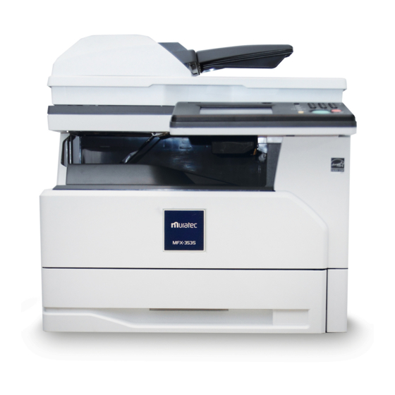
1 General Description 1.1 Product Description MFX-3595 Document tray Document guide Document output tray ADF cover USB connector Control panel Side cover 1 Front cover 2-bin tray (Optional) Paper cassette 1 Paper cassette 2 Paper cassette 3-4 (Optional) Side cover 2-4... - Page 6 MFX-3535 Document tray Document guide Document output tray ADF cover USB connector Control panel Side cover 1 Front cover 2-bin tray (Optional) Paper cassette 1 Paper cassette 2-4 (Optional) Side cover 2-4 Bypass tray Platen cover Network connector USB port Document glass ADF glass External...
-
Page 7: Specifications
1.2 Specifications See attached file. - Page 8 Specifications Item Sydney MLK TypeS-Mid Sydney MLK TypeS-High Copy Specifications Brand name Muratec Muratec Product name MFX-3535(Mid) MFX-3595(High) Manufacturing date 2015.3 2015.8 type Desktop type / Console type Desktop type / Console type Original table Fixed table Fixed table Scanning method...
- Page 9 Specifications Item Sydney MLK TypeS-Mid Sydney MLK TypeS-High Warm up time approx. 29 sec.(WUT3) approx. 29 sec.(WUT3) *The method for measurement refers *The method for measurement refers "WUP FCOT Measurement Method" "WUP FCOT Measurement Method" seat. seat. approx. 11 sec.(WUT1: PowerON - approx.
- Page 10 Specifications Item Sydney MLK TypeS-Mid Sydney MLK TypeS-High Memory Backup (Standard) No limit No limit *The user data clear is necessary at the *The user data clear is necessary at the time of the disposal. time of the disposal. Backup data Tx document(included PC Fax Tx), Rx Tx document(included PC Fax Tx), Rx document, List document as auto print,...
- Page 11 Specifications Item Sydney MLK TypeS-Mid Sydney MLK TypeS-High >>4-digit display of year >>AM/PM display USA:yes (LCD clock, LCD Settings, TTI and List) Standby Mode (Default) MyMFP MyMFP Input method By QWERTY key on touch panel By QWERTY key on touch panel EUR/AS1/AS2: AC230V±10 %...
- Page 12 Specifications Item Sydney MLK TypeS-Mid Sydney MLK TypeS-High Scanner Unit Scanning method >Scanning method Color CIS Color CIS >Lamp LED (RGB) LED (RGB) >Optical resolution (Max.) 600dpi x 600dpi 600dpi x 600dpi Color scanning >Color >Black & White >>Multi Level >>Bi Level >Grayscale 256 level 256 level...
- Page 13 Specifications Item Sydney MLK TypeS-Mid Sydney MLK TypeS-High >>>Max. Document Size Simplex: 216 x 900 mm (600dpi: 216 x Simplex: 216 x 900 mm (600dpi: 216 x 400mm) 400mm) Duplex: 216 x 356 mm Duplex: 216 x 356 mm >>>Min. Document Size Simplex: 120 x 100 mm Simplex: 120 x 100 mm Duplex: 120 x 139.5mm...
- Page 14 Specifications Item Sydney MLK TypeS-Mid Sydney MLK TypeS-High >Scan to Folder (SMB) 300dpi × 300dpi 300dpi × 300dpi >Scan to E-mail 300dpi × 300dpi 300dpi × 300dpi >Scan to FTP 300dpi × 300dpi 300dpi × 300dpi >Scan to CF/HDD >Scan to USB 300dpi ×...
- Page 15 Specifications Item Sydney MLK TypeS-Mid Sydney MLK TypeS-High >>100 dpi × 100 dpi 2.7sec/page (LTR SEF) 2.7sec/page (LTR SEF) Document scanning time (ADF: A4/SEF) >Copy (B/W) (Color) >Memory transmission >>SuperFine(ITU-T No.1 chart) N/A (ITU-T No.1 chart) N/A >>Fine (ITU-T No.1 chart) N/A >>Normal >>Grayscale (ITU-T No.1 chart)...
- Page 16 Specifications Item Sydney MLK TypeS-Mid Sydney MLK TypeS-High >>300 dpi × 300 dpi >>200 dpi × 200 dpi >>100 dpi × 100 dpi Continuous scanning time >B/W >>600 dpi × 600 dpi Simplex:40ipm Simplex:40ipm Duplex :32ipm Duplex :32ipm ...
- Page 17 Specifications Item Sydney MLK TypeS-Mid Sydney MLK TypeS-High > Resolution(Color PC Scan) yes, Text/Auto(Text&Photo)/Photo yes, Text/Auto(Text&Photo)/Photo yes, 100dpi/200dpi/300dpi/600x300dpi yes, 100dpi/200dpi/300dpi/600x300dpi (default: 300dpi/Auto) (default: 300dpi/Auto) >Contrast (Fax Tx) #REF! #REF! (Copy) #REF! #REF! (PC Scan B/W) #REF! #REF! (PC Scan Color) #REF! #REF! Scan Size setting Default: UR-ADF: Auto / FBS : A4 or...
- Page 18 Specifications Item Sydney MLK TypeS-Mid Sydney MLK TypeS-High Duplex Print speed (Max.) More than 10.0ppm(MAX/A4) More than 10.0ppm(MAX/A4) *The speed is down for temperature *The speed is down for temperature adjustment in continuously print. adjustment in continuously print. More than 6.0ppm (MAX/A4) More than 6.0ppm (MAX/A4) Alignment Upper left...
- Page 19 Specifications Item Sydney MLK TypeS-Mid Sydney MLK TypeS-High >Out put paper tray capacity [Main unit] [Main unit] More than 250 sheets (A4/Letter) (N-N More than 250 sheets (A4/Letter) (N-N environment, 80g/m2=20lb) environment, 80g/m2=20lb) [2-bin tray] [2-bin tray] 100 sheets (A4/Letter) (N-N 100 sheets (A4/Letter) (N-N environment, 80g/m2=20lb) environment, 80g/m2=20lb)
- Page 20 Specifications Item Sydney MLK TypeS-Mid Sydney MLK TypeS-High >No Developer detection Others >2-bin (Plain Paper/Simplex, yes(option) yes(option) Duplex) [Simplex] [Simplex] A4(SEF), A5(LEF/SEF), A6(SEF), A4(SEF), A5(LEF/SEF), A6(SEF), F4(SEF) F4(SEF) Letter(SEF), HalfLetter(LEF), Letter(SEF), HalfLetter(LEF), Legal(SEF), Executive(SEF) Legal(SEF), Executive(SEF) [Duplex] [Duplex] A4(SEF), A5(LEF/SEF), A6(SEF), A4(SEF), A5(LEF/SEF), A6(SEF), F4(SEF) F4(SEF)
- Page 21 Specifications Item Sydney MLK TypeS-Mid Sydney MLK TypeS-High Recording paper Skew Rate(Side) ±1.0%(simplex) / ±1.3%(duplex) ±1.0%(simplex) / ±1.3%(duplex) Postcard(bypass Tray) : ±1.5 % Postcard(bypass Tray) : ±1.5 % horizontal stretch ±0.5%(simplex) / ±1.0%(duplex) ±0.5%(simplex) / ±1.0%(duplex) vertical stretch ±0.5%(simplex) / ±1.0%(duplex) ±0.5%(simplex) / ±1.0%(duplex) Print Density over 1.2...
- Page 22 Specifications Item Sydney MLK TypeS-Mid Sydney MLK TypeS-High >Delayed Broadcast yes, Delayed time (Max.) : 31 days yes, Delayed time (Max.) : 31 days Group transmission 100groups 100groups N in 1 transmission 90°rotate transmission Enlarge Transmission (ADF/FBS) Duplex Transmission Insert Destination's name (Programmed in One-touch/Speed dials) into Letterhead Cover page...
- Page 23 Specifications Item Sydney MLK TypeS-Mid Sydney MLK TypeS-High Reception mode (USA,JPN) FAX Ready, TEL/FAX Ready, FAX/TEL FAX Ready, TEL/FAX Ready, FAX/TEL Ready, ANS/FAX Ready, TEL Ready Ready, ANS/FAX Ready, TEL Ready (EUR, AS) FAX Ready, TEL Ready Receiving alarm Rx Time stamp yes(Only Fax Rx) yes(Only Fax Rx) Special Function...
- Page 24 Specifications Item Sydney MLK TypeS-Mid Sydney MLK TypeS-High >>>Batch Tx >>>Polling Rx >>>Continuous polling Rx >>>F-code Tx >>>F-code polling Rx >>List print >>># of characters >>>OneTouch Dial list >>>SpeedDial list >>>Program OneTouch list >>>Tx reserved Commands >>>Activity journal list >>>Group list >>>Machine setting list >>>Junk fax protection Dial list...
- Page 25 My Jobs Registration F-Code Box Address Book List Group List My Jobs List Journal List Auto Distribution List Security Function >Closed network Transmission(Muratec proprietary) >Closed network Reception(Muratec proprietary) >>Closed network Passcode >ID Check Transmission (Muratec proprietary) page 18 of 66...
- Page 26 Specifications Item Sydney MLK TypeS-Mid Sydney MLK TypeS-High >Confirmation of Broadcast Destinations (Off,On,Broadcast Only) (Off,On,Broadcast Only) >Twice Dialing >>Twice Dialing(speed dial) >>Broadcast >Security Reception Protect Setting >Copy Protect >Fax Protect yes (Protect the operation from Control yes (Protect the operation from Control Panel, Excluding PC-Fax.) Panel, Excluding PC-Fax.) >Scan Protect...
- Page 27 Specifications Item Sydney MLK TypeS-Mid Sydney MLK TypeS-High E-mail Tx of Total List Lawyer Office Application Energy Saving >Special Key >Low power mode no(no light sleep) no(no light sleep) >>Entering time setting range no(no light sleep) no(no light sleep) >Sleep Mode >>Entering time setting range USA: 1-240min USA: 1-240min...
- Page 28 Specifications Item Sydney MLK TypeS-Mid Sydney MLK TypeS-High >#of destinations to send MAI: MAI: report(E-mail) 3 (1 of them is the prefixed MAI service 3 (1 of them is the prefixed MAI service number) number) Other: Other: >>Brief Report text on the E- yes (# of Drum replacements, yes (# of Drum replacements, mail body...
- Page 29 Google Drive(Scan) DocManager(Scan) (USA)Yes (USA)Yes Remote Panel for tablets (Other)No (Other)No iOS Android Muratec Mobile(Print Apps) iOS Android QR Code Function QR CodeData QR Code Advanced Features QR Code Decode Scan FAX/I-FAX with QR Code ・ Reception Notification ・ Routing of Received FAX/I-FAX N/A QR Code Decode Method ・...
- Page 30 Specifications Item Sydney MLK TypeS-Mid Sydney MLK TypeS-High Number of Thumbnails Rotation ・ Preview from Thumbnail Enlarge ・ Preview from Thumbnail Thumbnail of Security Print Document PC-FAX Basic Function Support for Network Communication Protocol HTTP/HTTPS/RAW/LPD HTTP/HTTPS/RAW/LPD Data Format TIFF TIFF # of User 100(fix) 100(fix)
- Page 31 Specifications Item Sydney MLK TypeS-Mid Sydney MLK TypeS-High Transmission Priority Application communication F-Code Transmission (ITU-T) ITU-T SubAddress ITU-T Password Delayed Transmission Max. Delayed Time Select Sender's Name(TTI) Auto Line Select PC-FAX Tx detail Tx Dialog Windows Dialog Windows Dialog Select TX Location Direct address input/Tx by One-touch/Speed Dial by Address Book...
- Page 32 Specifications Item Sydney MLK TypeS-Mid Sydney MLK TypeS-High AND/OR ("AND" in a routing table, "OR" between ("AND" in a routing table, "OR" between the routing tables) the routing tables) Routing Destination User 100 (fixed) 100 (fixed) # of User 100 (fixed) 100 (fixed) # of User Group no...
- Page 33 Specifications Item Sydney MLK TypeS-Mid Sydney MLK TypeS-High Time setting (Start/End) Forced print of routed docs Routing setting operation from op panel Forced print of routed docs. Suspend of routing (by record) Suspend of routing (All records) Exceptional distribution no (Included in normal distribution no (Included in normal distribution notice Function Comm.
- Page 34 Specifications Item Sydney MLK TypeS-Mid Sydney MLK TypeS-High approx. 29sec approx. 29sec Warm up time *The method for measurement refers *The method for measurement refers "WUP FCOT Measurement Method" seat. "WUP FCOT Measurement Method" seat. within 23sec (Tentative) within 23sec (Tentative) Cold Start Time (FCOT3) *The method for measurement refers *The method for measurement refers...
- Page 35 Specifications Item Sydney MLK TypeS-Mid Sydney MLK TypeS-High Scan Size Setting A4(SEF), A5(LEF), F4(SEF), A4(SEF), A5(LEF), F4(SEF), Letter(SEF), HalfLetter(LEF), Legal Letter(SEF), HalfLetter(LEF), Legal Copy reservation ># of jobs Interrupt copy Last Job Copy protection Irregular size copy Electric sorting Independent zoom setting for the orientation(%) >Directional Magnification in 1% step...
- Page 36 Specifications Item Sydney MLK TypeS-Mid Sydney MLK TypeS-High Lead Resistration URADF:±2.2mm(1:1) URADF:±2.2mm(1:1) >1:1 (ADF/URADF/FBS) FBS:±2.2mm(1:1) FBS:±2.2mm(1:1) >1:2(ADF/URADF/FBS) >2:1(URADF) >2:2 (URADF) Side Resistration URADF:±2.9mm(1:1) URADF:±2.9mm(1:1) >1:1 (ADF/URADF/FBS) FBS:±2.6mm(1:1) FBS:±2.6mm(1:1) >1:2(ADF/URADF/FBS) *1st Cassette *1st Cassette >2:1(URADF) >2:2 (URADF) Recording paper Skew Rate(Lead) URADF:±1.5%(1:1) URADF:±1.5%(1:1)...
- Page 37 Specifications Item Sydney MLK TypeS-Mid Sydney MLK TypeS-High ># of characters 40 characters 40 characters ># of redial 0-14 times / Initial: 2 times(US) 0-14 times / Initial: 2 times(US) 0-14 times / Initial: 2 times(EUR) >Redial interval 0-5 min. / Initial: 1 min.(US/EUR) 0-5 min.
- Page 38 Specifications Item Sydney MLK TypeS-Mid Sydney MLK TypeS-High Call catch at power failure yes (by external telephone) yes (by external telephone) Call request Handset External telephone yes (USA:possible to connect the yes (possible to connect the answering answering machine) machine) Phone line Cable Modular cover >TEL1...
- Page 39 Specifications Item Sydney MLK TypeS-Mid Sydney MLK TypeS-High Department tracking list >Manual printing >Auto printing User Access & Control List yes (Total List, ordered by user index) yes (Total List, ordered by user index) Communication Cost list by department basis Copy Cost list by department basis no Batch transmission >Box list...
- Page 40 Specifications Item Sydney MLK TypeS-Mid Sydney MLK TypeS-High >Japanese >Barcode/OCR 32 fonts (Option) (PCL5e Only) 32 fonts (Option) (PCL5e Only) >Cyrillic 15 fonts (PCL5e Only) 15 fonts (PCL5e Only) Emulation yes (Xerox Phaser 5500) yes (Xerox Phaser 5500) Font >Latin 136 fonts 136 fonts >Japanese...
-
Page 41: First Print Out Time
100 dpi x 100 dpi 100 dpi x 100 dpi Interface USB/LAN USB/LAN Data Transfer Mode Muratec Proprietary Muratec Proprietary Document scan time >600 dpi (Color) >>TEXT (ITU-T #1 chart) *Refer to Scanner Unit specifications *Refer to Scanner Unit specifications >>PHOTO (ITU-T #1 chart)... - Page 42 Specifications Item Sydney MLK TypeS-Mid Sydney MLK TypeS-High >400 dpi (ITU-T #1 chart) >300 dpi (Color) >>TEXT (ITU-T #1 chart) *Refer to Scanner Unit specifications *Refer to Scanner Unit specifications >>PHOTO (ITU-T #1 chart) *Refer to Scanner Unit specifications *Refer to Scanner Unit specifications >>PHOTO/TEXT (ITU-T #1 *Refer to Scanner Unit specifications *Refer to Scanner Unit specifications...
- Page 43 Specifications Item Sydney MLK TypeS-Mid Sydney MLK TypeS-High >>Windows Vista Home Basic (x86/x64) >>Windows Vista Home Premium (x86/x64) >>Windows Vista Ultimate (x86/x64) >>Windows Vista Business (x86/x64) >>Windows Vista Enterprise >>Windows Server 2003 Standard Edition >>Windows Server 2003 Standard x64 Edition >>Windows Server 2003 Enterprise Edition >>Windows Server 2003...
- Page 44 Specifications Item Sydney MLK TypeS-Mid Sydney MLK TypeS-High >CPU Performance Depends on the Operating System Depends on the Operating System >Required Memory quantity Depends on the Operating System Depends on the Operating System >Required Disk Space for driver 10MB or higher 10MB or higher installation Scanner Driver...
- Page 45 Specifications Item Sydney MLK TypeS-Mid Sydney MLK TypeS-High >Scan to User yes (TIFF) (running change) yes (TIFF) (running change) >Scan to USB Memory yes(TIFF, PDF) yes(TIFF, PDF) >WIA (Windows Image Acquisition) WinMe/XP Scan Advanced Functions Scan specified area yes (can not set custom size) yes (can not set custom size) Scan Document Preview Rescan...
- Page 46 Specifications Item Sydney MLK TypeS-Mid Sydney MLK TypeS-High Post Time Setting (Scan to Shared Box) Comments Setting (Scan to Shared Box) Hold Time Setting (Scan to Circulation) Deadline Setting (Scan to Processing) Scan counter tabulation by user group Scan counter tabulation by user yes (running change)...
- Page 47 # of Locations Group Tx # of Groups Security S/MIME PGP/MIME Rx E-mail → Forward to Fax (Offramp Gateway) T.37 Standard(FAX=XXX@XXX) Muratec Proprietary LightningFAX Direct SMTP Transmission Direct DNS Reroot Tx Fax/E-mail mixed Tx Duplex scanning Manual duplex scanning Auto Document Division normal mode(1stack→1file)...
- Page 48 Mail Rx with the attachment file TIFF-FX ・Profile-S ・Profile-F ・Profile-J ・Profile-C ・CCITT yes (PDF made by Muratec machine yes (PDF made by Muratec machine # of Memory Reception 250 (include G3 Fax) 250 (include G3 Fax) Rx by using POP3 page 41 of 66...
- Page 49 Received Mail Routing Routing Conditions All received Mail Routing Conditions setting Mail address by User name (exp: XXXX@) by Domain Name(exp:@XXXX) yes (Backward match *muratec.co.jp) yes (Backward match *muratec.co.jp) by Mail Address(exp: yes (Full match) yes (Full match) XXXX@XXXX) Subject...
- Page 50 Specifications Item Sydney MLK TypeS-Mid Sydney MLK TypeS-High Sort Print >Electric Sort yes, (Default: Off) yes, (Default: Off) >Offset Sort yes, (Default: Off) *When using paper other than A4, Letter, or Legal size, the machine may not perform the shift sorting function correctly due to environmental variation >Criss Cross Resolution...
- Page 51 Specifications Item Sydney MLK TypeS-Mid Sydney MLK TypeS-High Security Print ># of Users unlimited (due to memory capacity) unlimited (due to memory capacity) ># of stored jobs per user >Box Name User Password User Password >I.D.Code 24 hours (deleted after 24 hours without 24 hours (deleted after 24 hours without >Document Hold Period notice)
- Page 52 Specifications Item Sydney MLK TypeS-Mid Sydney MLK TypeS-High >>Windows Server 2003 Enterprise x64 Edition >>Windows Server 2003 Datacenter Edition >>Windows Server 2003 Datacenter x64 Edition >>Windows Server 2008 Standard (x86/x64) >>Windows Server 2008 Enterprise (x86/x64) >>Windows Server 2008 Datacenter (x86/x64) >>Windows Server 2008 R2 Datacenter(×64)...
- Page 53 Specifications Item Sydney MLK TypeS-Mid Sydney MLK TypeS-High >>>HP-UX yes (PCL 5e, PS3) yes (PCL 5e, PS3) Version: 11i v1/ 11i v1.5 / 11i v1.6 / 11i Version: 11i v1/ 11i v1.5 / 11i v1.6 / 11i v2/11i v3 v2/11i v3 yes (PCL 5e, PS3) yes (PCL 5e, PS3) >>>AIX...
- Page 54 Specifications Item Sydney MLK TypeS-Mid Sydney MLK TypeS-High >>Windows 98 Second Edition >>Windows Millennium Edition >>Windows NT 4.0 Workstation (SP6a or later) >>Windows 2000 Professional >>Windows XP Home Edition >>Windows XP Professional >>Windows XP Professional x64 Edition >>Windows Vista Home Basic (x86/x64) >>Windows Vista Home Premium (x86/x64)
- Page 55 Specifications Item Sydney MLK TypeS-Mid Sydney MLK TypeS-High >>Windows 8 Professional (x86/x64) >>Windows 8 Enterprise (x86/x64) >>Windows 10 Enterprise yes(running change) yes(running change) (x86/x64) >>Windows 10 Education yes(running change) yes(running change) (x86/x64) >>Windows 10 Pro (x86/x64) yes(running change) yes(running change) >>Windows 10 Home (x86/x64) yes(running change) yes(running change) >>Windows RT...
- Page 56 Specifications Item Sydney MLK TypeS-Mid Sydney MLK TypeS-High Creating print port yes (Standard TCP/IP) (Default: 192.168. yes (Standard TCP/IP) (Default: 192.168. Test print of security print initial setting of InfoMonitor Creating shortcut on desktop >InfoMonitor >Scan to Print Monitor yes (Default: Off)(running change) yes (Default: Off)(running change) >Cover Page Editor Startup menu registration...
- Page 57 Specifications Item Sydney MLK TypeS-Mid Sydney MLK TypeS-High ・User's Unread Document Display no User Information Item ・User Name 64 characters 64 characters ・User ID yes 64 characters yes 64 characters ・Password 28 characters 28 characters ・Type (Gateway User) ・Company ・Department Name (User Group Name) ・Group name ・TEL...
- Page 58 Specifications Item Sydney MLK TypeS-Mid Sydney MLK TypeS-High ・Status ・User Name yes (OB user name) yes (OB user name) ・User Group Name ・Progress ・# of pages ・Print Time Job Cancel yes (by job) yes (by job) Job order change Communication Log yes (Control Panel/Browser)...
- Page 59 Specifications Item Sydney MLK TypeS-Mid Sydney MLK TypeS-High # of Log max.500 max.500 Items on the Communication Log ・Destination Address ・# of Pages ・Comm. Mode ・Comm. Time ・Date&Time ・Result ・Subject ・Details Error Details Server Response Broadcast Locations yes(max. 400 characters) yes(max.
- Page 60 Specifications Item Sydney MLK TypeS-Mid Sydney MLK TypeS-High TCP/IP Settings Setting Method yes (Control panel/Browser) yes (Control panel/Browser) TCP/IP Setting IP Address Subnet Mask yes (max. 1 addresses) yes (max. 1 addresses) Gateway Address yes (max. 2 addresses) yes (max. 2 addresses) DNS Server Address ・DNS Suffix DHCP Setting (ON/OFF)
- Page 61 Specifications Item Sydney MLK TypeS-Mid Sydney MLK TypeS-High # of Body Text Template Items for Body Text Template ・Template Name yes, 40 characters yes, 40 characters ・Subject yes, 80 characters yes, 80 characters ・Body Text yes, 1024 characters yes, 1024 characters Show recipients on Tx e-mail yes (show all recipients) yes (show all recipients)
- Page 62 Specifications Item Sydney MLK TypeS-Mid Sydney MLK TypeS-High ・Report Tx ・Canceled Jobs Non-available functions when the Archive setting is ON Archiving Destinations ・E-mail Address ・Fax Number ・Folder ・FTP Address ・User File Format of archived document PDF / TIFF (default: TIFF) PDF / TIFF (default: TIFF) Index file of archived documents yes, when the network folder is selected...
- Page 63 Specifications Item Sydney MLK TypeS-Mid Sydney MLK TypeS-High Admin.) Tx completion (when "leave" is selected) CoverPage ・ON/OFF Setting ・Template Select ・Default Subject ・Default Message Check Message Print ON/OFF when PC-Fax Tx Error (only User) Document ・Reference ・Delete (only Admin.) Storage Period of Rx Document Auto Routing Function ・Routing Method IS type(Message board type)
- Page 64 Specifications Item Sydney MLK TypeS-Mid Sydney MLK TypeS-High Admin.) Shared Rx Function ON/OFF Documents Documents documents Bulletin Board Setting (only Bulletin Board Function ON/OFF Billing Period Initial Setting Documents documents Circulation Setting Circulation Function ON/OFF Auto Delete after circulation Storage Period of documents after circulation Admin.
- Page 65 Specifications Item Sydney MLK TypeS-Mid Sydney MLK TypeS-High ・Available # of settings Unacceptable Service Name yes (select from the service name list) yes (select from the service name list) Initialize yes (Browser/Control Panel) yes (Browser/Control Panel) Machine Setting (only Admin is allowed) Setting Method Browser/Control Panel...
- Page 66 Specifications Item Sydney MLK TypeS-Mid Sydney MLK TypeS-High Organization Default Organization Description1 N/A Default Organization Description1 N/A # of characters Company Name Company Name attribution 1 company company Company Name attribution 2 Characters 49 characters 49 characters Search Rule Setting Default setting Default setting Search Key Rule Setting...
- Page 67 Specifications Item Sydney MLK TypeS-Mid Sydney MLK TypeS-High Search Start Point Auto Search Point detect Search Method of Authentication Windows NT 4.0 Server Windows Server 2003, 2008 Authentication of Domain with Windows NT 4.0 Server Windows Server 2003, 2008 Mail Address Relation Acquisition of User Mail Address Windows NT 4.0 Server Windows Server 2003, 2008...
- Page 68 Specifications Item Sydney MLK TypeS-Mid Sydney MLK TypeS-High Developing Unit Waste Toner Box no (within a machine) no (within a machine) Fixing cleaner Handset >Type >Curl code >Phone line type Telephone stand AC Power Cord Phone line connect cord Localize Kit type: no Non Localize Kit type: yes Tray, Hopper >Document hopper...
- Page 69 Specifications Item Sydney MLK TypeS-Mid Sydney MLK TypeS-High >Parallel cable >USB cable Ferrite Core EUR : yes(3pcs) USA : yes(2pcs) USA : yes(2pcs) Bundle software Documents CD Driver installation CD Consumables Toner cartridge ># of print pages 24,000 sheets (ISO/IEC 19752, 24,000 sheets (ISO/IEC 19752, equivalent value) equivalent value)
- Page 70 Localize Kit KM:yes (prepared by customer) Muratec: TBD >AC Power Cord >Phone line connect cord >Panel Cover (KM: Overlay type, Muratec: Cover type) >Printed Manuals >>Safety Information Manual >>User's Guide >>Software Setup Guide >>Quick Installation Guide >PDF Manuals (Including the documents CD) >>User's Guide...
- Page 71 Specifications Item Sydney MLK TypeS-Mid Sydney MLK TypeS-High >Recording paper size label >Cassette number label >One-touch label >Soft key label >Business reply mail >Protect Sheet label >Contact Address card >Card case >Others Carrier sheet Upgrade Memory >Install manual Paper supply unit yes, Universal type yes, Universal type >Recording paper quantity...
- Page 72 Specifications Item Sydney MLK TypeS-Mid Sydney MLK TypeS-High Bypass Tray Duplex Unit >Install manual Fax receiving Lamp Rotation print kit InternetFax kit Mechanical counter >Install manual Safety kit for Condensation (Scanner unit) Safety kit for Condensation (Printer unit) Dust-proofing Cover Safety kit for Earthquake OfficeBridge RFID reader...
- Page 73 Specifications Item Sydney MLK TypeS-Mid Sydney MLK TypeS-High Erp Lot26 (2013) Energy star (USA/CAN) RoHS Energy star Others >PTS (DEU) Yes(EUR) Attached Approval label ID label >Telecom >>Conformity mark (JPN) >>Telecom mark (EUR) >>FCC No. (USA) yes (USA/included on the ID label) yes (USA/included on the ID label) >>IC No.
-
Page 75: Machine Composition
2 Machine Composition 2.1 Document scanning section 2.1.1 Auto Document Feeder (ADF) Section ADF (Auto Document Feeder) is a device that feeds the document continuously one page by one to the scanning section automatically. It consists mainly of document tray, Tx cover, inner guide, and platen cover. When the device is categorized by its functions, it consists of separator section that picks up each page of documents, register section that detects the leading edge of the document and controls the timing so that the document does not skew, and scan section that scans the document. -
Page 76: Document Detection
Document detection The sizes of the documents are detected by the following sensors; Detection Sensor Document presence Leading and trailing edge detection DS3 (Back side) DEXIT Scanning section for simplex document The document sensor (DS2) is placed at scanning position to detect the leading edge and trailing edge of the document. - Page 77 When the backside of the document is scanned, the document will be discharged. Scanner (Reversible) (Switching)
- Page 78 2.1.2 Flat Bed Scanner (FBS) section The FBS (Flat Bed Scanner) section consists of document glass (pane) and optical reading section (CIS). The CIS (Contact Image Sensor) carried on CIS holder keeps the focal length by moving along the pane. CIS moves and thereby exposes the lamp light uniformly to the document.
-
Page 79: Recording Section
2.2 Recording section Recording paper feed path The recording paper is separated from the remaining paper by friction of the pickup roller. The paper is trans- ferred along the paper guide until it reaches the register roller. Then it is transferred to the exit tray by the register roller. - Page 80 Sorting mechanism (MFX-3595 only) When finishing the printouts using the shift sort function, every second set of the printouts will be shifted 1 inch off to the horizontal direction and ejected on the exit tray. Paper exit direction Shift direction (1 inch) When the trailing edge of paper is nipped only by the exit roller assy, the shift motor drives, and the exit roller assy will be shifted to its shift position.
- Page 81 Paper feed timing chart...
- Page 82 Shift motor is for MFX-3595 only: Warming-up 1 When the power is turned on, or the side or front cover is closed, the machine controls the warming-up temperature of the fuser. 2 Devices start working in the following order: Fan, RX2 motor, Dup CL1, RX1 motor, REGCL, 2bin motor, and shift motor.
- Page 83 Two-page shift copy 1 The machine starts to control the printing temperature of the fuser when the start key is pressed at copy mode. 2 Devices start working in the following order: Fan, RX2 motor, Dup CL1, and RX1 motor. 3 In a predetermined condition, the feed clutch turns on, and the pick up roller feeds a paper.
-
Page 84: Image Prosessing Section
2.3 Image prosessing section The image processing is roughly divided into the following steps: 1. Charging This step charges the drum negatively using the scorotron charger working on corona discharge system. 2. Exposure This step creates an electrostatic latent image on the drum surface by lighting the LED head (print head) according to the image data. -
Page 85: Developing Unit
2.3.1 Developing unit The machine uses an one-component nonmagnetic toner (negative). The toner is charged by friction be- tween developing roller and toner supply roller, and between developing roller and blade, and adheres to the developing roller. Part name Part name Blade OPC drum Developing roller... -
Page 86: Charging Mechanism
2.3.3 Charging mechanism The drum is charged evenly through a grid mesh by corona discharging of a multi-stylus electrode. The stylus type charger concentrates discharging to the grid mesh side, which generates less ozone than wire- electrical discharging. The generated ozone is removed by the ozone filter while emission. Part name Part name Charger case... - Page 87 2.3.4 Exposure mechanism The LED print head lights according to the image data transferred from the print controller, and exposes the drum surface. The exposed surface loses the energy of charge, and an invisible static image is created on the drum surface. Charge Non-exposed area Exposed area...
-
Page 88: Development Mechanism
2.3.5 Development mechanism The static image created in exposure step is developed through toner adherence. The toner is transferred using the potential difference between the drum potential and developing bias charged on transfer roller. The exposed area on the drum surface has higher potential (VL) than the developing bias (Vb) that makes the toner transfer from the developing roller to the drum surface. -
Page 89: Separation Mechanism
2.3.7 Separation mechanism The electrostatic force on the paper is removed by a separator stylus, and the paper separates from the drum. The drum separation scraper also helps the paper separate from the drum. Part name Part name Separation scraper Star roller Paper Separation stylus... -
Page 90: Cross Section
2.3.9 Toner transfer mechanism Part name Part name Toner cartridge Drum cartridge Toner supply route Toner collection route Cross section Part name Part name Toner cartridge Drum cartridge Toner discharge opening Toner supply opening 2-16... - Page 91 2.3.10 Discharge mechanism After transfer step, erase light is exposed on the drum to neutralize remaining charge and to provide for the next charging. Part name Part name Eraser lamp OPC drum 2-17...
-
Page 92: Fusing Mechanism
2.3.11 Fusing mechanism The toner image transferred on to the paper is securely fixed. A heat roller system is used as the fusing system. The toner image is fused by heater roller heated by the heater lamp, and securely fixed by the pressure between the heater roller and press rollers. A thermistor detects and controls the heater roller temperature. -
Page 93: Fusing Temperature
Fusing temperature 1) Warming Up After the initialization of the printer, warming up of the printer starts and the Heater Lamp turns ON until the temperature of the Heater Roller reaches approx. 170 °C. 2) Printing When the printer obtains the printing command from its controller, the Heater Roller is main- tained at 180 °C. -
Page 94: Interconnect Block Diagram
2.4 Interconnect Block Diagram MFX-3595 MFX-3595 Connection Diagram (1/3) 2013/04/23 ASSY PSU-OL DD1-Y9100-40 AC SWITCH ASSY PSU-OL_B SW(SSW) *SDDJF30200 ZA1-04386-20 DD1-Y9101-40 CBL-ASSY LA CBL-ASSY LA CBL-ASSY LA-303B -303B -303B 69 9 6 6 9 DD1-0865 DD1-0865 DD1-08650-50 0-50 0-50 ZA1-01031... - Page 95 MFX-3595 Connection Diagram (2/3) 2013/04/23 ZA1-03631- ZA1-03631- 60 0 ZA1-03631- ZA1-03631- 6 6 0 CORE (1T) x 2p CORE (1T) x 2p CORE (1T) x 2p CORE (1T) x 2p cs. 6214 FBS Home Sensor (SG2A141) Z08-13358-00 15 5 1 1 5...
- Page 96 MFX-3595 Connection Diagram (3/3) 2013/04/23 CBL-ASSY STAPL CBL-ASSY STAPL CBL-ASSY STAPL CBL-ASSY STAPL ER-FG 6 6 6 66 6 DD1-0897 DD1-0897 DD1-08970-50 0-50 BRACKET MOTOR COVER TX DD1-10240-60 DD1-1001*-60 50 0 5 5 0 ADF MOTOR /MADF_B COVER PLATEN CBL-ASSY URADF DR...
- Page 97 MFX-3535 MFX-3535 Connection Diagram (1/3) 2013/04/23 ASSY PSU-OL DD1-Y9100-40 AC SWITCH SW(SSW) *SDDJF30200 ASSY PSU-OL_B ZA1-04386-20 DD1-Y9101-40 CBL-ASSY LA CBL-ASSY LA CBL-ASSY LA-303B -303B 7 7 7 7 69 9 6 6 9 DD1-0865 DD1-08650-50 CBL-ASSY CBL-ASSY CBL-ASSY CBL-ASSY PANEL PANEL PANEL PANEL...
- Page 98 MFX-3535 Connection Diagram (2/3) 2013/04/23 ZA1-03631- ZA1-03631- 0 6 6 0 CORE (1T) x 2pcs. CORE (1T) x 2p 6214 FBS Home Sensor (SG2A141) Z08-13358-00 15 5 1 1 5 CBL-AS CBL-AS SY HS CBL-AS CBL-AS SY HS SY HS SY HS DD1-0827 0-50...
- Page 99 MFX-3535 Connection Diagram (3/3) 2013/04/23 CBL-ASSY STAPL CBL-ASSY STAPL CBL-ASSY STAPLER-FG ER-FG ER-FG 66 6 6 6 6 DD1-0897 DD1-0897 DD1-08970-50 0-50 0-50 BRACKET MOTOR COVER TX DD1-10240-60 DD1-1001*-60 5 5 0 50 0 ADF MOTOR /MADF_B COVER PLATEN CBL-ASSY URADF DR CBL-ASSY URADF DR CBL-ASSY URADF DR IVE-FG IVE-FG...
-
Page 100: Circuit Board Constructions
2.5 Circuit board constructions MFX-3595 URADF URADF URADF URADF Heater URADF URADF URADF STAMP SLND CLTCH SNSR LAMP (HN) Utility LVPS Power MD0033 Driver Driver MOTOR GPIO CNTRL HVPS Image Processing CLTCH SNSR LAMP USB H x 2pcs. USB Memory... - Page 101 MFX-3535 URADF URADF URADF URADF Heater URADF URADF URADF STAMP SLND CLTCH SNSR LAMP (HN) Utility LVPS Power MD0033 Driver Driver MOTOR GPIO CNTRL HVPS FPGA (QVGA) Image Processing Touch PANEL CLTCH (save) Speaker SNSR (save) LAMP PCB PANEL PCB PANEL PCB PANEL PCB PANEL SubSW...
-
Page 102: Main Control Board
• General I/O (Printer and scanner sensors, printer clutches, fans) • Eraser lamp • Print motor • Toner motor • Shift motor (MFX-3595 only) • Mechanical counter (option) • Cassette board (sensor and clutch) (option) • 2bin tray board (sensor and motor) (option) MD0033 This is the FPGA for image processing of scanned image. - Page 103 Panel board This board consists of keys, touch panel, LCD, FPGA/MPU controlling the LED, and their peripheral circuits. Scanner connection board This board relays signals from ADF to motors, clutches, solenoids, and sensors. It is controlled by SoC and printer FPGA on the main control board. Power is not supplied during energy save setting.
- Page 104 Network Control Unit (NCU) board The NCU board provides the connection to the telephone line. It consists of the interface circuit, ring signal detector and telephone control circuit. SURGE ABSORBER AGND Electronic Inductor, Off-Hook, Pulse Dial, and TIP, and RINGVI SmartDAA Modem Control...
-
Page 105: Sensors
2.6 Sensors 2.6.1 Sensor Locations The following illustration shows the relative positions of the machine’s sensors. D EXIT TEMP F COVER TOS_TC JAMC2 OPEN OP PES OP TXIL INTRLCK SWBK TOS_DC *MFX-3595 only TRAYS OPEN 2-31... -
Page 106: Sensor Descriptions
INTRLCK Inter lock Interlock switch for printers Mechanical Switch Home Position Detects position of the shift unit. Photo interrupter *1: MFX-3595 only PES OP Paper empty sensor Detects presence of recording Photo interrupter paper in the 2nd paper cassette (PES2) -
Page 107: Adjustment Procedures
3 Adjustment Procedures 3.1 Field service program modes The fax machine feature maintenance modes for machine adjustment. Each mode is listed below along with the command used to activate the mode and a brief functional description. Press <Mode> about two seconds until you hear the beep twice. When you press “... - Page 108 Service Program Explanation Operation Page Cleaning mode This mode rotate the Pickup roller and registra- <Mode>, <*>, <4>, <6> 3-109 tion roller automatically so that you can clean the surface of them. Network switch mode Adjust the network parameter. <Mode>, <*>, <5>, <1> 3-109 Coverage measure- You can scan and check the black ratio of a...
-
Page 109: Machine Parameter Adjustment
3.2 Machine parameter adjustment 3.2.1 Setting the machine parameters These switches are used to program internal machine parameters. 1. From standby, press <Mode>, <*>, <0>, <0>. 2. Press [Edit Parameters]. 3. Call up the desired switch. 4. Select the desired parameter by pressing the box. 5. -
Page 110: Clearing The Machine Parameters
• Mirror carriage standby position adjustment • Background level adjustment starting position • Loop volume adjustment at DRS sensor • Controlling paper curl • Adjustment for timing to shift paper (MFX-3595 only) • Paper loop volume adjustment • Density adjustment 301 ~ 357 Blank page detection for ... - Page 111 3.2.4 Details Machine Parameter 000 — Factory use only Machine Parameter 001 Initial Adjust Usage / Comments Setting Factory use only Factory use only Factory use only Factory use only Adjust the attenuation level for image data signal output. Memory switch 11 is active -1.0 dB -7.0 dB -8.0 dB...
- Page 112 Machine Parameter 030 Switch Initial Adjust Usage/Comments Setting Back side of document 76543210 25 steps 00011001 +5.29 mm URADF scanner registration adjustment (Horizontal) 00010000 +3.39 mm Adjusts the start point to 00001000 +1.69 mm scan the document. The plus setting increases 00000000 0 mm the left margin and the minus...
- Page 113 Machine Parameter 033 Initial Switch Adjust Usage/Comments Setting Back side of document Switch 76543210 Settings Leading edge document 127 steps 01111111 +10.67 mm margin adjustment (URADF) 00100000 +2.69 mm Adjusts the leading edge margin from Document 00010000 +1.34 mm Sensor 2 (DS2) to the start of scanning the position.
- Page 114 Machine Parameter 035 Switch Initial Adjust Usage/Comments Setting Front side of document 76543210 25 steps 00011001 +5.29 mm URADF scanner registration adjustment (Horizontal) 00010000 +3.39 mm Adjusts the start point to 00001000 +1.69 mm scan the document. The plus setting increases 00000000 0 mm the left margin and the minus...
- Page 115 Machine Parameter 037 Initial Switch Adjust Usage/Comments Setting Adjustment of the scanning Switch 76543210 Settings stretching and squeezing for 76543210 URADF. 01111111 +1.27% (Vertical) 00010000 +0.16% The plus setting stretches the image data and the minus 00000100 +0.04% setting squeezes it. 00000000 Each setting changes by 0.01%...
- Page 116 Machine Parameter 039 Initial Switch Adjust Usage/Comments Setting Front side of document Switch 76543210 Settings Trailing edge document 127 steps 01111111 +10.76 mm margin adjustment (URADF) 00100000 +2.71 mm Adjusts document feed after the trailing edge of a docu- 00010000 +1.36 mm ment passes Document Sensor 2 (DS2).
- Page 117 Machine Parameter 041 Initial Switch Adjust Usage/Comments Setting Adjustment of the scanning Switch 76543210 Settings stretching and squeezing for 76543210 FBS. 01111111 +1.27% (Horizontal) 00010000 +0.16% The plus setting stretches the image data and the 00000100 +0.04% minus setting squeezes it. 00000000 Each setting changes by 0.01%...
- Page 118 Machine Parameter 043 Initial Switch Adjust Usage/Comments Setting Leading edge document When the shadow of document leading edge is margin adjustment for FBS scanned, increase the value. When the image or document leading edge is lack- Adjusts the leading edge ing, decrease the value.
- Page 119 Machine Parameter 060 Initial Switch Adjust Usage/Comments Setting Mirror carriage standby Switch 76543210 Settings position adjustment 127 steps 01111111 +10.67 mm Adjusts the number of steps from home sensor ON to 00100000 +2.69 mm standby position 00010000 +1.34 mm 1 step = 2 / 600 dpi (0.084 mm) 00001000 +0.67 mm...
- Page 120 Machine Parameter 066 Initial Switch Adjust Usage/Comments Setting Loop volume adjustment at Increasing this value may improve document skew DRS sensor but lead to noise or damage to document. Decreasing this value may improve noise or dam- age to document but document may not be fed To improve screw in URADF, normally.
- Page 121 Machine Parameter 090 Initial Switch Adjust Usage/Comments Setting Lowering the paper-pickup You can lower the paper-pickup temperature to temperature to reduce paper reduce paper curl. When you enable this setting, curl paper curl will be reduced but fusing quality will be 0: No poorer.
- Page 122 Adjustment for timing to shift When the roller leaves a mark on the back end of paper.(MFX-3595 only) the paper, increase the value. When the machine ejects the paper without sorting, You can use this mode when decrease the value.
- Page 123 Machine Parameter 301 ~ 357 — Density adjustment Initial Switch Adjust Usage/Comments Setting Density adjustment Switch 76543210 Settings at scanning 127 steps 01111111 Light See table below for param- eter numbers 126 steps 01111110 2 steps 00000010 1 step 00000001 0 step 00000000 Standard -1 step...
- Page 124 Machine Parameter 480 ~ 487 — Density adjustment Initial Switch Adjust Usage/Comments Setting Blank page detection Control blank page detection parameter. See table below for param- Switch 76543210 Settings eter numbers 127 steps 01111111 Easy detection 126 steps 01111110 2 steps 00000010 1 step 00000001...
-
Page 125: Memory Switch Adjustment
3.3 Memory switch adjustment 3.3.1 Setting the memory switches These switches are used to program internal machine parameters. 1. From standby, press <Mode>, <*>, <0>, <1>. 2. Press [Mem Switch Edit]. 3. Call up the desired switch by pressing [Prev] or [Next], or by pressing the numeric keys. 4. -
Page 126: Clearing The Memory Switches
3.3.2 Clearing the memory switches Resets the memory switches to factory defaults. 1. Press <Mode>, <*>, <0>, <1>. 2. Press [Mem Switch Clear]. 3. Press [Yes]. The memory switches will reset to factory defaults. 3.3.3 List • DIS detection condition • PBX mode dial pause • Redial in D.0.7 error • D TMF attenuation... - Page 127 • Number of HDLC end flags • Digital cable equalizer • Tone detection level • EYE-Q check level at 7200 bps • EYE-Q check level at 9600 bps • EYE-Q check level at 12000 bps • EYE-Q check level at 14400 bps • EYE-Q slice level • Check EYE-Q • EYE-Q check level at 2400 bps...
- Page 128 3.3.4 Details Memory switch 00x : Dialer Memory switch 000 : Initial Adjust Usage / Comments Setting Factory use only — Factory use only — CED detection condition Sets whether the detection should be strict not. Normal Strict 350 ms 500 ms 700 ms 1000 ms Switch 5 DIS detect time after dialing...
- Page 129 Memory switch 00x : Dialer Memory switch 001 : Initial Adjust Usage / Comments Setting Factory use only — Factory use only — DIS detection condition Sets whether the detection should be strict or not. Normal Strict 200 ms 300 ms 400 ms 500 ms Switch 5 PBX mode dial pause Sets the number of seconds the machine waits before dialing...
- Page 130 Memory switch 00x : Dialer Memory switch 004 : Initial Adjust Usage / Comments Setting Factory use only — Factory use only — Factory use only — Factory use only — DTMF attenuation See table below. The setting of this switch is available only when setting other than 0.
- Page 131 Memory switch 00x : Dialer Memory switch 005 : Initial Adjust Usage / Comments Setting Factory use only — Ring signal detect time Set the time that an incoming ring will not be detected after hanging up. Switch 654 100 ms 200 ms 300 ms 400 ms...
- Page 132 Memory switch 01x : Transmission Memory switch 010 : Initial Adjust Usage / Comments Setting Busy tone detection Set this switch to “0” if the ring tone of remote unit is mistaken 0 : No for a busy signal. 1 : Yes Fallback pattern (bps) 2400 4800...
- Page 133 Memory switch 01x : Transmission Memory switch 012 : Initial Adjust Usage / Comments Setting TTI clock type 0 : AM PM clock 1 : 24 hour clock TTI calendar type dd mm yyyy mm dd yyyy (default) yyyy/mm/dd TTI transmit When set at “0”, transmission of the TTI is disabled.
- Page 134 Memory switch 01x : Transmission Memory switch 015 : Initial Adjust Usage / Comments Setting Program individual autodi- Allows individual setting of memory switches 010 as attribute aler attributes 1, 011 as attribute 2, 012 as attribute 3 and 013 as attribute 4 0 : No when fax destination are programmed.
- Page 135 Memory switch 01x : Transmission Memory switch 017 : Initial Adjust Usage / Comments Setting Factory use only — Factory use only — Factory use only — Factory use only — Time between ANSam out- When using optical communication line, wait to make sure that put and CM output the terminal adopter has turned the echo-canceler off.
- Page 136 Memory switch 01x : Transmission Memory switch 018 : Initial Adjust Usage / Comments Setting Output attenuation for VoIP This setting is available only when unique switch 070-3 is ON. This setting will set output attenuation for VoIP separate to that of memory switch 011 bit 0-3.
- Page 137 Memory switch 02x : Reception Memory switch 020 : Initial Adjust Usage / Comments Setting Data error rate Determines the allowable number of erred lines out of total 0 : 10% lines received in a document. 1 : 20% Pause one second after A 2100 Hz CED signal disables echo suppression in some sending CED telephone equipment.
- Page 138 Memory switch 02x : Reception Memory switch 021 : Initial Adjust Usage / Comments Setting Factory use only — Factory use only — Factory use only — T1 timer Adjusts the T1 time-out. After the machine dials the remote 0 : 35 sec. machine’s phone number, it begins sending CNG and waits 1 : 20 sec.
- Page 139 Memory switch 03x : Modem Memory switch 030 : Initial Adjust Usage / Comments Setting Number of HDLC end flags Defines the number of HDLC end flags. Switch 7654 0000 0001 0010 Initial setting 0011 0100 0101 0110 0111 1000 1001 1010 1011...
- Page 140 Memory switch 03x : Modem Memory switch 032 : Initial Adjust Usage / Comments Setting EYE-Q slice level Setting this bit to “1” enables memory switch 032, bits 0-3 and 0 : Disable memory switch 031, bits 0-7 and enables EYE-Q check adjust- 1 : Enable ment.
- Page 141 Memory switch 05x : Printer Memory switch 050 : Initial Adjust Usage / Comments Setting Toner near empty detection Set the number of pages the machine can print until it detects point “Toner empty” (ISO/IEC 19753, equivalent value). 1 step = 120 pages Switch 76543210 Settings...
- Page 142 Memory switch 05x : Printer Memory switch 052 Initial Adjust Usage / Comments Setting Factory use only — Factory use only — Add remote fax mark to the Set this function to “1” to print an “R” on the journal report journal report when the location name is acquired from the remote fax ma- 0 : No...
- Page 143 Memory switch 05x : Printer Memory switch 054 : Initial Adjust Usage / Comments Setting Extended priority for name Switch 7654 printing on journal report 0101 Caller ID(USA), Number Display(JPN) 0100 Subscriber ID (TSI/CSI) Third priority 0011 Sender name (TTI) 0010 Phone number 0001...
- Page 144 Memory switch 06x : Remote reception Memory switch 060 : Initial Adjust Usage / Comments Setting Factory use only — CML relay off time after di- When dialing from the keypad, phone line noise may occur as aling the CML relay switches on and off. 0 : 1 sec.
- Page 145 Memory switch 06x : Remote reception Memory switch 062 : Initial Adjust Usage / Comments Setting Factory use only — Factory use only — Factory use only — CNG detect in Ans / Fax When set to “1”, the machine detects the CNG signal in Ans / ready Fax ready.
- Page 146 Memory switch 06x : Remote reception Memory switch 064 : Initial Adjust Usage / Comments Setting CNG detect period after Sets the period during which CNG is detected after the TAD TAD begins recording ICM begins recording incoming message. Switch 7654 Time 0000 0 sec...
- Page 147 Memory switch 06x : Remote reception Memory switch 065 : Initial Adjust Usage / Comments Setting Adjustment of CI detect Sets the time added to or reduced from the CI detect time. time Switch 76543 Time 11111 150 msec 11101 140 msec 01001 40 msec 00111...
- Page 148 Memory switch 07x : Operation Memory switch 070 : Initial Adjust Usage / Comments Setting Display error line The number of error lines contained in the received data will 0 : No be shown in the LCD. 1 : Yes Tonal line monitor Allows fax communication to be heard through the monitor speaker.
- Page 149 Memory switch 07x : Operation Memory switch 071 : Initial Adjust Usage / Comments Setting Factory use only — Factory use only — Print TCR with the original For easy identification, the first page of a document stored for page during memory trans- memory transmission will print along a TCR when the trans- mission when the result is mission result is error.
- Page 150 Memory switch 07x : Operation Memory switch 076 : Initial Adjust Usage / Comments Setting Timing to turn off the S- Adjust this setting when a private exchanger disconnects the Relay at fax reception. line when S-Relay is turned off. 7654 time 1111...
- Page 151 Memory switch 09x : Miscellaneous Memory switch 090 ~ 096 : Factory use only Memory switch 097 : Initial Switch Adjust Usage/Comments Setting Day light saving time This switch sets the month when the day light saving (Summer time) start month time (summer time) begins.
- Page 152 Memory switch 09x : Miscellaneous Memory switch 098 : Initial Switch Adjust Usage/Comments Setting Day light saving time This switch sets the month when the day light sav- (Summer time) end month ing time (summer time) ends. Switch 7 6 5 4 Month 0 0 0 0 October...
-
Page 153: Setting Individual Autodialer Attributes
3.4 Setting individual autodialer attributes This function allows the user to configure an individual address book entry with the settings shown in Memory Switches 010, 011, 012, 013 and 014. To set the individual attributes: 1. Change memory switch 15, bit 7 to “1”. (See “3.3.1 Setting the Memory Switches” for more information on changing memory switch 015.) 2. - Page 154 Attribute 1 ‑ Individual Autodialer Setting (Equivalent to Memory Switch 010) Initial Switch Adjust Usage/Comments Setting Busy tone detection Sets this switch to “0” if the ring tone of remote unit 0: No is mistaken for a busy signal. 1: Yes Fallback pattern (bps) 2400 4800...
- Page 155 Attribute 2 ‑ Individual Autodialer Setting (Equivalent to Memory Switch 011) Initial Switch Adjust Usage/Comments Setting The time between reception of CFR and transmission of data When CFR and data overlap due to line echo, increase the interval between CFR and data transmission using this switch.
- Page 156 Attribute 3 ‑ Individual Autodialer Setting (Equivalent to Memory Switch 012) Initial Switch Adjust Usage/Comments Setting TTI clock type 0 : AM PM clock 1 : 24 hour clock TTI calendar type dd mm yyyy (default) mm dd yyyy yyyy/mm/dd TTI transmit When set at “0”, transmission of the TTI is disabled.
-
Page 157: Unique Switch Adjustment
3.5 Unique switch adjustment 3.5.1 Setting the Unique Switches These switches are used to program internal machine parameters. 1. From standby, press <Mode>, <*>, <0>, <4>. 2. Press [Switch Edit]. 3. Call up the desired switch by pressing [ Prev] or [ Next] , or by pressing the numeric keys. 4. -
Page 158: Clearing The Unique Switches
3.5.2 Clearing the unique switches Resets the unique switches to factory defaults. 1. From standby, press <Mode>, <*>, <0>, <4>. 2. Press [Switch Clear]. 3. Press [Yes]. The unique switches will reset to factory defaults. 4. Press <Reset> to return the machine to standby. 3.5.3 List • Congestion tone detection • Enable the first tone key... - Page 159 • Printer density adjustment • Enable paper with Letterhead • Reduce received fax in Letter size • Enable toner saving mode • Paper selection priority • VoIP and Super G3 setting for Tx • Line monitor in Quick memory transmission • Rx document to polling document • Start copying even if no suitable paper size is set • Set custom paper for default PCL paper...
- Page 160 3.5.4 Details Unique Switch 00x : Dialer Unique Switch 000 : Initial Switch Adjust Usage/Comments Setting Factory use only Factory use only Factory use only Factory use only Factory use only Congestion tone detection Setting this switch to “0” ignores telephone line 0: No congestion tones.
- Page 161 Unique Switch 00x : Dialer Unique Switch 003 : Initial Switch Adjust Usage/Comments Setting Factory use only Display only direct input Set this switch to “0” to display all dial history on the number on redial list redial list. Set this switch to “1” to display only direct 0: No input number on the list.
- Page 162 Unique Switch 01x : Transmission Unique Switch 010 : Initial Switch Adjust Usage/Comments Setting Factory use only Factory use only Factory use only Factory use only Including TTI inside the Setting this bit to “0” transmit the document length document added with the TTI.
- Page 163 Unique Switch 01x : Transmission Unique Switch 015 : Initial Switch Adjust Usage/Comments Setting Factory use only Factory use only Factory use only Factory use only Factory use only Factory use only Returns from V21 to V8 0: No 1: Yes V.8 handshake in manual Determine I the handshaking will be done with V.8 transmission...
- Page 164 Unique Switch 01x : Transmission Unique Switch 018 : Initial Switch Adjust Usage/Comments Setting Factory use only Factory use only Factory use only Disconnect the line when Determine if the machine disconnect the phone line the transmission speed falls when the transmission speed fall down under 7200 down under 7200 bps bps.
- Page 165 Unique Switch 02x : Reception Unique Switch 020 : Initial Switch Adjust Usage/Comments Setting Factory use only Factory use only Factory use only Transmit CED signal Determines if sending CED signal. 0: No 1: Yes Factory use only Factory use only Printout the pages completed Determines if whether to printout the page which to receive during receiving...
- Page 166 Unique Switch 02x : Reception Unique Switch 022 : Initial Switch Adjust Usage/Comments Setting Document storage method JBIG Initial setting IMAGE MMR reception Used to determine the encoding method at DIS 0: No declaration. 1: Yes JBIG reception Used to determine the encoding method at DIS 0: No declaration.
- Page 167 Unique Switch 02x : Reception Unique Switch 029 : Initial Switch Adjust Usage/Comments Setting Factory use only Displays the message “No Set this switch to “1” will delete the message Network Connection.” “No Network Connection.” Use this switch if the 0 : Yes machine is not used in a network.
- Page 168 Unique Switch 03x : Modem Unique Switch 030 : Initial Switch Adjust Usage/Comments Setting Factory use only Factory use only 3429 baud symbol rate when If the error frame often occurs because of the communicating at V.34 symbol rate is too high, setting this switch to 0: No “1”...
- Page 169 Unique Switch 03x : Modem Unique Switch 032 : Initial Switch Adjust Usage/Comments Setting Factory use only Factory use only Factory use only Factory use only Factory use only ANSam output time The time limit to output the ANSam (A sinewave 0: 3 seconds signal at 2100 Hz amplitude-modulated).
- Page 170 Unique Switch 03x : Modem Unique Switch 037 : Initial Switch Adjust Usage/Comments Setting Factory use only Factory use only Factory use only The delay before post- If retraining occurs due to the low reception signal message is transmitted level and few delay of the telephone line, it may overlap the second post-message.
- Page 171 Unique Switch 05x : Printer Unique Switch 050 : Initial Switch Adjust Usage/Comments Setting Factory use only Factory use only Factory use only Factory use only Factory use only Factory use only Factory use only Smooth printing for printing normal document 0: No 1: Yes Unique Switch 051 :...
- Page 172 Unique Switch 05x : Printer Unique Switch 053 : Initial Switch Adjust Usage/Comments Setting Printer density adjustment. Switch 76543210 Settings 00000000 Not available 00000001 Lightest 00000010 00000101 Standard 00001001 Darkest 00001010 Adopt “Standard” ↓ Unique Switch 054 ~ 055 — Factory use only Unique Switch 056 : Initial Switch...
- Page 173 Unique Switch 07x : Operation Unique Switch 070 : Initial Switch Adjust Usage/Comments Setting Factory use only Factory use only Factory use only Factory use only VoIP and Super G3 setting This switch enables the following two menu added: for Tx 0: Off 1 Tx Mode (Normal Tx/Specific Tx): 1: On...
- Page 174 Unique Switch 07x : Operation Unique Switch 072 : Initial Switch Adjust Usage/Comments Setting Factory use only Factory use only Factory use only Factory use only Start copying even if no Set this switch to “1” to start copying even if the set suitable paper size is set paper size does not fit the document size.
- Page 175 Unique Switch 07x : Operation Unique Switch 077 : Initial Switch Adjust Usage/Comments Setting Print time out on PCL text 7 6 5 4 printing (at local printing) 1 1 1 1 15 minutes 1 1 1 0 1 minute/step 1 1 0 1 Adjustable range: 1~15 1 1 0 0...
- Page 176 Unique Switch 07x : Operation Unique Switch 079 : Initial Switch Adjust Usage/Comments Setting Print time out on PCL (at 7 6 5 4 local printing) 1 1 1 1 15 minutes 1 1 1 0 1 minute/step 1 1 0 1 Adjustable range: 1~15 1 1 0 0 minutes...
- Page 177 Unique Switch 08x : Miscellaneous Unique Switch 080 : Initial Switch Adjust Usage/Comments Setting Factory use only Factory use only Default tab on scan read Set the tab which should be displayed when you screen switch to scan read screen. Switch 5 4 [Apps] [PC/USB]...
- Page 178 Unique Switch 08x : Miscellaneous Unique Switch 085 : Initial Switch Adjust Usage/Comments Setting Factory use only Print/Send the consumable order sheet when the drum is NOTE near end 0: Yes For this feature to work correctly, you must 1: No register several items.
- Page 179 Unique Switch 09x : Miscellaneous Unique Switch 090 — Factory use only Unique Switch 091 : Initial Switch Adjust Usage/Comments Setting Factory use only Factory use only Priority of fusing on When you set this switch to “1”, fusing on paste- pasteboard board improves but paper may curl.
- Page 180 Unique Switch 09x : Miscellaneous Unique Switch 096 : Initial Switch Adjust Usage/Comments Setting Warn that fuser switches are Turn to switch to “Yes”(1) to enable following in envelope-printing position operation: 0: No - Display a warning message when copying or 1: Yes printing envelopes is finished that the fuser switches are in envelope-printing position.
- Page 181 Unique Switch 09x : Miscellaneous Unique Switch 099 : Initial Switch Adjust Usage/Comments Setting Enabling RemotePanel 0: No 1: Yes Enabling blank page detection 0: No 1: Yes Enabling Scan to GoogleDrive 0: No 1: Yes Enabling Scan to Dropbox 0: No 1: Yes Enabling Scan to Box...
-
Page 182: Clear Programmed Data / User Settings
3.6 Clear programmed data / user Settings User programmed information such as address book entries, date, time, Transmit Terminal Identifier (TTI), Subscriber ID, etc., are stored in the unit’s SD card. This function does not clear the machine parameters, memory switches and unique switches. 1. -
Page 183: Monitor
3.8 T.30 monitor In all binary coded facsimile control procedures the HDLC frame structure is utilized. The basic HDLC struc- ture is shown below. Preamble Binary coded information Non-standard facilities frame(NSF) Called subscriber identification frame (CSI) Digital identification frame (DIS) Facsimili Facsimili Frame... - Page 184 3.8.3 How to see the print out (Example for fax transmission) (Example for fax reception) TxFrame : Signals sent by machine printing T.30 report RxFrame : Signals received from remote machine DATA: Additional 8-bit octet information to clarify facsimile procedures. In the list, the data are in hexa- decimal digits.
- Page 185 NSF, NSC, NSS: NSF, NSC, NSS are nonstandard unit frames. The first three bytes of the FIF are specified by T.30. The subsequent digits are individually determined by the manufacturers. The first byte refers to the country code. The second byte is a spare; it is 00 (hex) presently. The third byte is the manufacturer code. TxFrame RxFrame D A T A...
-
Page 186: Printer Maintenance Mode
A transmission with PPR signal: The error frame in fax reception is identified using the post-message signal and PPR signal. TxFrame RxFrame D A T A PPS MPS BF 4F 00 00 0F BC F0 00 FF FF FF FF FF FF FF FF FF FF FF FF FF FF FF FF FF FF FF FF FF FF FF FF FF FF FF FF FF In PPS signal FIF, the pages, blocks and frames are displayed one value less than the real value. -
Page 187: Service Report Printing
3.9.2 When “Checkout error : XX” message is displayed 1. Press <Mode>, <*>, <0>, <6>. 2. Press [Service Call]. 3. Detail of printer error will be displayed. See “4.3 Checkout error” on page 4-3 for the printer error messages and an explanation of each are outlined. - Page 188 Days Used / Work Days Days since the machine is installed / Days the machine has worked ROM Version The ROM version of machine Panel ROM version The panel ROM version of MFX-3595 is displayed. This is for MFX-3595 only. 3-82...
- Page 189 First page of the report. The resettable counter cleared date is printed with six figure of date / month / year. 3-83...
- Page 190 Second page of the report 3-84...
- Page 191 Third page of the report 3-85...
- Page 192 Fourth page of the report Fifth page of the report The fifth page is for MFX-3595 only. However this sheet is for engineer only. 3-86...
-
Page 193: Monitor Speaker
3.11 Monitor speaker If you need to monitor the signal of fax communication, turn this mode to on. You can hear the signal sound with machine’s speaker during fax transaction. 1. Press <Mode>, <*>, <0>, <8>. 2. Select the monitor type from [ON until DIS] or [ON]. 3. - Page 194 Display Item Detail Drum Cartridge Usage 1 History of used drum cartridge 1 (Drum star day, printed pages, and serial number) Drum Cartridge Usage 2 History of used drum cartridge 2 (Drum star day, printed pages, and serial number) Drum Cartridge Usage 3 History of used drum cartridge 3 (Drum star day, printed pages, and serial number) Toner Replaced...
-
Page 195: Printer Test
3.12.2 Printer Test The printer test mode offers ten different test patterns as shown below. Checkered Squares Paper scum Halftone Halftone2 White Black Ladder LED Head Test 6% Pattern 1. Press <Mode>, <*>, <0>, <9>, then select [Test Pattern Print]. 2. -
Page 196: Set Background Level
3.12.3 Stamp test mode This mode tests the optional stamp. The stamp will be stamped on the document at a regular interval. 1. Load test documents into the automatic document feeder (ADF). 2. Press <Mode>, <*>, <0>, <9>, then select [Stamp Test Mode]. 3. - Page 197 3.12.6 Make color gamma The machine has a color gamma data table as color scanning correction data. The color gamma table ad- justs RGB color balance, and is unique per machine because of the optical variation. Both the flash memory on main control board and SD card keep the color gamma table, and the same data will be saved on both parts when you make a color data though below operation.
-
Page 198: Print Machine Parameters, Memory Switch And Unique Switch Settings
3.13 Print machine parameters, memory switch and unique switch settings This function instructs the unit to print a list of the machine parameter, memory switch and unique switch set- tings. The list shows the default and current settings for each. 1. -
Page 199: Lcd Test
Every time when you press <Start> the color of LCD switches in following order. When all the colors are tested, the test is finished. MFX-3595: White Yellow Purple Red Light blue Green Blue Black MFX-3535: White Black 3. -
Page 200: Dram Check
3.14.4 DRAM Check This mode is used to test the DRAM memory, or document memory. 1. Press <Mode>, <*>, <1>, <1>, then select [DRAM Check]. 2. Enter the test data. 3. Depending on the amount of DRAM in the unit, press <0>. 4. -
Page 201: Line Tests
3.15 Line tests This mode offers several internal tests and ability to monitor certain unit output functions. Included are relay tests, modem signal output monitoring, and DTMF output monitoring. NOTE To monitor the tones, an external monitoring device must be connected to the telephone line jack. 3.15.1 Relay Test This mode tests the on/off operation of various relays and switches. -
Page 202: Tonal Signal Test
3.15.2 Tonal signal test The tonal signal test permits the unit’s output tones to be monitored. 1. Press <Mode>, <*>, <1>, <2>. 2. Press [Tonal]. 3. Select your desired tonal signal test. When it is selected, it will be highlighted. Refer to the table below. -
Page 203: Dtmf Output Test
3.15.3 DTMF output test The DTMF output test permits the unit’s DTMF tones to be monitored. 1. Press <Mode>, <*>, <1>, <2>. 2. Select [DTMF]. 3. Select your desired tonal DTMF tone. When it is selected, it will be highlighted. Display Signal Display... -
Page 204: Mirror Carriage Transfer Mode
3.16 Mirror carriage transfer mode IMPORTANT The machine is shipped with mirror carriage locked to protect the machine’s mirror carriage during ship- ping. When installing the machine, turn the power on and perform the following: 1. Press <Mode>, <*>, <1>, <4> . 2. -
Page 205: Consumable Order Sheet
3.17 Consumable order sheet When the drum cartridge is near end of its design life or the toner cartridge is near empty, the machine prints (or transmit) the consumable sheet. 23 24 Dealer’s fax number Customer’s name Customer’s department Customer’s address 1, 2 Customer’s account number Customer’s telephone number Customer’s fax number registered by Initial... -
Page 206: Set Consumable Order Sheet
3.17.1 Set consumable order sheet Follow the instructions on the display and enter following items: Items Descriptions Dealer code Enter dealer code. Dealer name Enter dealer name. Dealer Tel No Enter dealer’s telephone number. Up to 20 characters can be entered. Dealer Fax No Enter dealer’s fax number. -
Page 207: Dram Clear
3.17.3 Print consumable order sheet To check the information has been registered correctly, print the consumable order sheet. 1. Press <Mode>, <*>, <1>, <5>. 2. Select [Order Sheet List]. 3. Select settings, and press [Yes]. 3.18 DRAM clear This clears the image storage memory. 1. -
Page 208: Life Monitor Maintenance
3.19 Life monitor maintenance 3.19.1 Resettable counter clearing Clear the counter of the machine. The following counter will be cleared: • Scanned pages per mode (copy/scan/fax/print) • Scanned times per mode (copy/scan/fax) • Pages per scanner part (ADF/FBS) • Times per scanner part (ADF/FBS) •... -
Page 209: Sensor Input Test
3.20 Sensor input test You can check the sensor status. When the sensor operates, the value next to sensor name changes from OFF to ON or from ON to OFF. For example, when open the paper cassette 1, the CAS1:OFF change to CAS1: ON. - Page 210 Cassette sensor list: Name Status Name Status CAS1 Casette 1 open/closed PES1 Paper empty sensor for cassette 1 OPEN OFF: Closed (PES) OFF: No paper ON: Open ON: Paper detected SIDE_OP Interlock sensor (side cover open/ (JAMC) closed) OFF: Closed ON: Open CAS2 Casette 2 open/closed...
-
Page 211: Printer Diagnostic Mode
Rotate the Rx motor 2 Shift Dir : Shows the shift motor rotate direction (MFX-3595 only) Shift Mtr : Shift unit shifts and returns to its home position(MFX-3595 only) Clutch 1 : Turn on clutch of cassette 1 Clutch 2 :... -
Page 212: Network Service Mode
3.22 Network service mode This mode provides the following two items: • Delete administrator password • Initialize authentication method 3.22.1 Delete administrator password You can clear the administrator password. 1. Press <Mode>, <*>, <2>, <4>. 2. Press [Delete Manager]. 3. Press [Yes]. 3.22.2 Initialize authentication method You can initialize the authentication mode, and return it to its factory default (Stand-alone). -
Page 213: Paper Setting Change
3.24 Paper setting change Paper settings will be changed from Letter size to A4 size. This mode allows the following functions to enable: Paper setting change mode Default scan size for Copy/Scan/Fax(ADF) Auto Auto Default zoom ratio for copy(ADF) 100% 100% Default paper size for copy (ADF) 1st cassette... -
Page 214: Set Service Report
3.25 Set service report 3.25.1 Set the service report If using this feature, you should be enter following items: Items Descriptions Send Service Report Machine does not send the service report. Machine transmits service report according to this setting. E-mail Machine send the service report via e-mail according to this setting. -
Page 215: Reset Printer Trouble
3.26 Reset printer trouble This mode clears the service call. Clear the warning when the trouble is settled. If fuser warming up error is settled, turn the machine OFF and ON following this operation. 1. Press <Mode>, <*>, <4>, <5>. 2. - Page 216 4. Select the desired parameter by pressing the box. 5. To navigate through the machine parameter settings: • The bits are ranged from 7 (left) to 0 (right). • Press [ ] or [ ] of the cursor key to move the cursor. • Press <0>...
- Page 217 Network switch 004: Initial Switch Adjust Usage/Comments Setting Scan to e-mail retry interval 11111111 255 seconds 00111100 60 seconds 00000010 2 seconds 00000001 1 second 00000000 3 seconds (default) Network switch 005 ~ 006: Factory use only Network switch 007: Initial Switch Adjust...
- Page 218 Network switch 011: Initial Switch Adjust Usage/Comments Setting Synchronizing interval of internet 11111111 255 minutes time between machine and SNTP server 00111100 60 minutes 00000010 2 minutes 00000001 1 minute 00000000 15 minutes (default) Network switch 012: Initial Switch Adjust Usage/Comments Setting Maximum permissible hours of...
-
Page 219: Coverage Measurement
Network switch 089: Initial Switch Adjust Usage/Comments Setting Encryption communication at SSL connection for HTTP client 0: Enable 1: Disable Network switch 090 ~ 099: Factory use only 3.29 Coverage measurement You can scan and check the black ratio of a document. 1. -
Page 220: Printer Control Parameter Mode
3.31 Printer control parameter mode The following settings are available for the PDL : Adjustment Parameter • Enable PS3 tray setting • Cassette designation command • Paper size designation command Change barcode font width Tray number command for PCL 5 044 ~ 048 Tray number command for PCL XL 050 ~ 054... - Page 221 Printer control parameter 000 ~ 026 : Factory use only Printer control parameter 027 : Initial Adjust Usage/Comments Setting Factory use only Factory use only Factory use only Enable PS3 tray setting Set this bit to “1” to customize tray number command on PS3. 0: No For detail setting, see “Printer control parameter 064 ~ 068 :”...
- Page 222 Printer control parameter 028 : Initial Adjust Usage/Comments Setting Change barcode font Change barcode fonts wider or narrower by step. The steps are from 7 to -7, but some fonts are limited in width available steps. And some fonts cannot be changed. For details, see table below.
- Page 223 Printer control parameter 044 ~ 048 : Initial Adjust Usage/Comments Setting Tray number command Set the tray number command for PCL 5. 0 to 23 are available. for PCL 5 To enable this setting, turn printer parameter 27 bit 1 to “1”. Printer control parameter 044: Bypass tray (default 2) Printer control parameter 045: Cassette 1 (default 4) Printer control parameter 046: Cassette 2 (default 1)
-
Page 224: Network Capture (Packet Capture)
Printer control parameter 064 ~ 068 : Initial Adjust Usage/Comments Setting Tray number command Set the tray number command for PS3. 0 to 23 are available. Other values have no operation for PS3 guarantee. To enable this setting, turn printer parameter 27 bit 4 to “1”. Printer control parameter 064: Bypass tray (default 0) Printer control parameter 065: Cassette 1 (default 1) Printer control parameter 066: Cassette 2 (default 2) -
Page 225: Storage Maintenance
3.32.2 Capturing packet data from machine control panel When you capture packets using USB memory device, a file named “tcpdump.cap” will be created on the root. If there already exists a file with the same file name, that file will be overwritten with the new data. 1. -
Page 226: Initialize Protection
3.33.2 Erasing storage CAUTION When you perform this operation, the SD memory card cannot be recovered through “Resetting Storage” or any other operations. 1. Press <Mode>, <*>, <5>, <9>. 2. Press [Disable SD Storage]. 3. Press [Yes]. 3.34 Initialize protection Use this function to initialize protect passcode and administrator's password. -
Page 227: Color Fine Adjustment
3.35 Color fine adjustment Adjust the scan color. You can adjust RGB mode for front side of document, and make fine difference for back side of document. 1. Press <Mode>, <*>, <6>, <2>. 2. Press either [Register / Change]. When you press [Initialize] and then [Yes], all the parameters return to their default value. 3. -
Page 228: Service Function Menu
3.37 Service function menu All the field service modes are available from the menu. 1. Press <Mode>, <*>, <7>, <7>. 2. Select the desired service function to use. 3.38 Counter information maintenance The machine has the counter data saved on both the EEPROM and SD card with its serial number connect- ed. -
Page 229: Rds Data Copy
3.39 RDS data copy This mode enables you to import and export binary data including machine settings. Exporting RDS data 1. Connect a USB memory to the machine. 2. Press <Mode>, <*>, <9>, <4>. 3. Press [USB Export]. 4. Select the location of where to save the data, and press [Next]. 5. -
Page 230: Update The Firmware
: “Manual Update”. Auto Update To update the ROM automatically, create a “Boot” folder on the root directory of USB memory, then create a folder in it, and save the firmware in it. MFX-3595: USB flash memory Boot 3595aUSA 3595a_USA_xxxxxx.bin... - Page 231 MFX-3535: USB flash memory Boot 3535aUSA 3535a_USA_xxxxxx.bin • “3535a” indicates machine name. • “xxxxxx” indicates the ROM version. NOTE Save only one firmware in the folder. Auto Update is not available when two or more firmware are stored. 1. Press the power button on the control panel, and turn off the machine. 2.
- Page 232 Updating the ROM manually either by selecting the latest ROM version or by selecting the desired version. Two or more ROM data can be saved on an USB memory. Create a folder, and save the firmware in it. MFX-3595: USB flash memory 3595aUSA 3595aUSA_Ver.txt...
- Page 233 1. Connect the USB memory in which the firmware is stored. 2. Press <Mode>, <*>, <9>, <8> 3. Press [Update from the USB]. 4. Press either [Update to the latest version] or [Specify with specified version]. 5. When you have selected [Update to the latest version], go to step 8. When you have selected [Specify from list to update], press [File selection (Main):].
- Page 234 Update 1. Press <Mode>, <*>, <9>, <8>. 2. Press [Update from the network]. 3. Press either [Update to the latest version] or [Specify with specified version]. 4. When you have selected [Update to the latest version], and go to step 7. When you have selected [Specify from list to update], press [Main Unit Version:].
- Page 235 0002 Machine is printing. 0003 Machine is operating and printing. 0004 Machine is scanning. 0005 Machine is printing and scanning. 0006 Machine is operating and scanning. 0007 Machine is operating, printing, and scanning. 0008 Machine is communicating. 0009 Machine is operating and communicating. 000A Machine is printing and communicating.
-
Page 236: Network Service Functions
1. Start the web browser on computer. 2. Type the machine’s IP address in the URL address field followed by “/service”. e.g. http://192.168.1.10/service 3. Enter login ID and password. : muratec Password : service 4. Now the network service settings are available. - Page 237 3.43.1 E-mail detailed status 1. Open the network service screen. (See page 3-130.) 2. Click [E-mail Settings]. 3. Set each item, and click [Save]. Items Instructions X-Mailer Some SMTP servers do not send e-mail without X-Mailer information (mailer name) in the e-mail header. In such case, input the X-Mailer information here.
- Page 238 3-132...
- Page 239 3-133...
- Page 240 3.43.2 Convert dialling characters in e-mail gateway functions The following dialling characters will be converted to certain characters specified here: Pause (/P) Tone (/T) Flash (/F) For example, when you enter “&A” for “/P” (pause) and specify a fax number like “123/P456”, the number will be converted to “123&A456”...
-
Page 241: Firmware Update
1. Open the network service screen. (See page 3-130.) 2. Click [Firmware Update]. 3. Click [Browse] to browse the location where the firmware is located. “Control Panel” is only for MFX-3595. Machine: 3535a_USA_A0A0A0.bin, 3595a_USA_A0A0A.bin Control panel: 3595P_USA_A0A0A_update.bin 4. Click [Update]. -
Page 242: Print Data Capture
3.43.5 Print data capture User can capture and store print commands (PCL/GDI/PS/FAX) as a “.PRN File”. This feature supports con- current processing to printing and capture print commands. 1. Open the network service screen. (See page 3-130.) 2. Click [Print Data Capture]. 3. - Page 243 3.43.6 Network capture For details of this future, refer to “3.32 Network capture (Packet capture)”. 1. Open the network service screen. (See page 3-130.) 2. Click [Network Capture]. 3. Enter the necessary information. 4. Click [Capture Start] to start capturing the data. 5.
-
Page 244: Machine Settings
3.43.7 Modifying the session control time Modify the session time between the machine and the OfficeBridge users here. The factory default is 30 minutes. When there is no communication between the machine and the OfficeBridge user during this time, the user will forcibly be log out. -
Page 245: Remote Operation
3.43.9 Remote operation You can operate the machine through web browser. The buttons you can not touch through the browser are shaded like <Login> or <Personal Mode> on the im- age below. Sound and lamp light cannot be checked. 1. Open the network service screen. (See page 3-130.) 2. - Page 246 3-140...
-
Page 247: Troubleshooting Procedures
4 Troubleshooting procedures 4.1 Troubleshooting flow chart Check the detail of the trou- ble. Is the user operating the ma- Does the problem still oc- chine correctly? curs with correct opera- tion? Is the problem solved by "Initial checks" operation? ... -
Page 248: Initial Checks
4.2 Initial checks Check all items: Check items Remedy Machine Is the power on? Turn the power on. Are the covers closed correctly? Close all covers correctly. Is the recording paper set? Set the recording paper. Are the toner and drum set correctly? Set the toner and drum correctly. -
Page 249: Checkout Error
4.3 Checkout error 4.3.1 Checking the error message When“ Checkout error” message is displayed, follow the steps below to check the service call number. 1. Press <Mode>, <*>, <0>, <6>. 2. Press [Service Call]. 3. Check the service error code on the display. Details code for the errors are displayed in parentheses. - Page 250 4.3.2 Troubleshooting 04: RX motor 2 error 08: RX motor error Causes: The machine has detected motor-lock signal while the motor is driving. Suggested corrective action: 1. Check the connection of harness between the motor and main control board. 2. Replace the motor. 3.
- Page 251 50:Shift unit error (MFX-3595 only) Detail code: 1: The shift unit does not return to the home position. 2: The shift unit does not move from the home position. Suggested corrective action: Detail code 1 1. Check the connection between then shift sensor (HP sensor) and the main control board.
-
Page 252: System Error
Startup system error A circuit board or SD card has a problem. Replace the main control board, the SD card, or the panel board. (Panel board is for MFX-3595 only) Billing data access error Billing data write error has occurred. -
Page 253: Communication Trouble
4.5 Communication trouble 4.5.1 Fax communication error Deatail error code are printed on T.30 monitor. Detail Phase Error code Description Journal Redial Message Note Error code Tx Phase A D.0.1 0001 Local busy detection. The sending was stopped. Please try again. D.0.2 0002 Busy Tone detected... - Page 254 Detail Phase Error code Description Journal Redial Message Note Error code Tx Phase B T.2.2 110D DIS or DTC that FIF is 00 00 00 Confirm the remote fax. Normally, this error does has been received. DTS requires not occur. hang up.
- Page 255 Detail Phase Error code Description Journal Redial Message Note Error code Rx Phase B R.1.1 2011 T1 time-out error No, if no Confirm the remote fax. Occurs at manual page is reception. received at auto reception R.1.2 2012 Compatibility error Confirm the remote fax.
- Page 256 Detail Phase Error code Description Journal Redial Message Note Error code Rx Phase D R.4.2 2042 Cannot receive MPS/EOM/EOP Confirm the remote fax. R.5.1 2051 Cannot receive RR DNC received R.5.2 2052 Error occurred while ECM data mode Rx V34 start R.8.1 2081 V8 process did not finished...
- Page 257 4.5.2 Network communication error Scan to e-mail transmission results Error code Display Message Description Countermeasure Transmission Not able to transmit. DNS server name resolution failed. Check the DNS setting. error Mail server is not found. Not able to transmit. Authentication method in SMTP is differ- Check the SMTP/POP setting is correct.
- Page 258 Internet FAX reception result Error code Descrpition Countermeasure The MFP is not compatible with the e-mail Ask the sender to send an internet fax in a compatible file format. attached image. The MFP refused to forward the received •To respond to the forward request, set “Response to Fax Forwarding Request” in E-mail Settings > Optional E-mail e-mail.
- Page 259 Scan to folder, Scan to Printer, and ScanTag transmission result Error Description Check message Countermeasure NTSTATUS values Details Code 10002 <Stop> was pressed during — Wait for a while, and try to — scanning with non-batch send again scan function 9999 System error System error occurred...
- Page 260 Error Description Check message Countermeasure NTSTATUS values Details Code 1033 Connection error Not able to be connect • Check that host name on STATUS_FILE_LOCK_CONFLICT A Lock request conflicted with an the network. 0xC0000054 existing lock or specified an invalid • Check DNS server address, STATUS_LOCK_NOT_GRANTED mode, or an Unlock requested at- DNS suffix, and WINS server...
- Page 261 Error Description Check message Countermeasure NTSTATUS values Details Code 2001 Connection error Not able to be connect • Check that host name on STATUS_INVALID_SMB Non-specific error code, returned the network. 0x00010002 under the following conditions: • Check DNS server address, resource other than disk space DNS suffix, and WINS server exhausted (e.g.
- Page 262 Error Description Check message Countermeasure NTSTATUS values Details Code 3023 File read and write error Not come by the file reading Check that the destination STATUS_DATA_ERROR Data error (CRC) and writing. shared folder is not read/ 0xC000003E write protected. STATUS_CRC_ERROR 0xC000003F 3024 STATUS_INFO_LENGTH_MISMATCH...
- Page 263 Error Description Check message Countermeasure NTSTATUS values Details Code 1005 Login error Not able to log in. • Check that the entered user STATUS_ACCESS_DENIED Access denied, the client's context name and password are cor- 0xC0000022 does not permit the requested rect.
- Page 264 Error Description Check message Countermeasure NTSTATUS values Details Code 2004 Login error Not able to log in. • Check that the entered user — The client does not have the name and password are cor- necessary access rights within the rect.
- Page 265 Scan to FTP server and ScanTag transmission result Error Description Check message Detail Countermeasure Description Code 10002 9999 System error System error occurred. An error occurred because Retry later. there was a temporary sys- 9000 tem memory shortage. Connection error Not able to be connected Name resolution failed •Check DNS server address is...
- Page 266 OfficeBridge Docs transmission result Error Description Check message Detail Countermeasure Description Code 1000 Transmission succeed — — — — 9999 System error System error occurred. An error occurred because Retry later. HTTPC_ERROR_PARAMETER there was a temporary sys- HTTPC_ERROR_INITIALIZE tem memory shortage. HTTPC_ERROR_FINALIZE HTTPC_ERROR_FILE HTTPC_ERROR_NO_DATA...
-
Page 267: Image Quality Problems
4.6 Image quality problems Go through the following steps to solve the problem: Check the machine parameters for image quality adjustments and see if the problems solves. 2. Adjust the background level and see if the problem solves. (See “3.12.5 Set background level” on page 3-90.) Clean the document glass and document pad in advance. - Page 268 4.6.1 Typical fault images 1. Blank image 2. Black image 3. Low image density / rough image ABCDE ABCDE ABCDE ABCDE ABCDE 4. Dark image density 5. Blank lines/ Blank spots 6. Void areas ABCDE ABCDE ABCDE ABCDE ABCDE ABCDE ABCDE ABCDE ABCDE...
- Page 269 4.6.2 Blank image Scanner section Section Step Check items Result Remedy Scanner section Is the scanner drive transmission Check and replace as neces- mechanism in good condition? sary. Do the connection from CIS to main Reconnect / Replace harness. control board remain intact? Is the trouble settled with above 1.
- Page 270 4.6.3 Black image Scanner section Section Step Check item Result Remedy Scanner section 1 Does lamp turn ON when making Check step 4 and onward copy with open platen cover? Reconnect / Replace harness Do step 1 again. Replace main control board. Does the voltage level of pin1-3 of P8A on the main control panel change to +3.3V?
- Page 271 4.6.4 Low image density / rough image Scanner section Section Step Check item Result Remedy Scanner section 1 Do the connection from CIS to main Reconnect / Replace harness. control board remain intact? Are the document glass, document Clean pad and ADF glass dirty? Is the CIS lens dirty? Clean, or replace the part and adjust the background level...
- Page 272 4.6.5 Dark image density Scanner section Section Step Check item Result Remedy Scanner section 1 Are the ADF glass and document Clean glass dirty? Are the CIS (lens and lamp) and Clean document glass dirty? Is the CIS installed properly? Install it properly Do the connection from CIS to main Reconnect / Replace harness.
- Page 273 4.6.6 Blank lines Scanner section Section Step Check item Result Remedy Scanner section 1 Are the document glass and docu- Clean ment pad dirty? Do the connection from CIS to main Reconnect / Replace harness. control board remain intact? Is the trouble settled with above 1.
- Page 274 4.6.7 Void areas Scanner section Section Step Check item Result Remedy Scanner section 1 Is the document glass dirty? Clean Do the connection from CIS to main Reconnect / Replace harness. control board remain intact? Is the trouble settled with above 1.
- Page 275 4.6.8 Black lines Scanner section Section Step Check item Result Remedy Scanner section 1 Are the CIS (lens and lamp) and Clean document glass dirty? Do the connection from CIS to main Reconnect / Replace harness. control board remain intact? Is the trouble settled with above 1.
-
Page 276: Black Spots
4.6.9 Black spots Scanner section Section Step Check item Result Remedy Scanner section 1 Is the document glass dirty? Clean Do the connection from CIS to main Reconnect / Replace harness. control board remain intact? Is the trouble settled with above 1. - Page 277 4.6.10 Smear on back Printer section Section Step Check item Result Remedy Paper path Is paper path dirty with toner? Clean Fuser unit Are the fusing rollers or separation Clean / Replace scraper dirty or damaged? Transfer section 3 Is the transfer roller dented or dam- Replace aged? Circuit boards...
-
Page 278: Uneven Image Density
4.6.11 Uneven image density Scanner section Section Step Check item Result Remedy Scanner section 1 Are the ADF glass and document Clean glass dirty? Is the shading-sheet located under Clean or replace CIS, and ad- the size cover dirty? just the background level Is the CIS (lens and lamp) dirty or Clean or replace CIS, and ad- deteriorated? - Page 279 4.6.12 Periodically uneven image Scanner section Section Step Check item Result Remedy Scanner section 1 Is the FBS motor drive gear cracked Clean / Replace or dirty with foreign object? Is the scanner motor secured prop- Secure properly erly? Is the CIS secured properly? Secure properly Are the CIS belt attached loosely? Adjust the belt tension.
-
Page 280: Gradation Reproduction Failure
4.6.13 Gradation reproduction failure Scanner section Section Step Check item Result Remedy Scanner section 1 Is the shading-sheet located under Clean or replace CIS, and ad- the size cover dirty? just the background level Are the ADF glass and document Clean glass dirty? Do the connection from CIS to main... -
Page 281: Scanner Related Trouble
4.7 Scanner related trouble Mechanical Errors Symptom Possible Cause Countermeasure While ADF does not feed the The pickup roller is dirty or worn Clean the roller. feeding a document. out. Replace the roller. document The power of the separation Adjust the separation pressure. roller is getting decrease. - Page 282 Symptom Possible Cause Countermeasure While The scan starting and DS2 sensor defect 0 Press <Mode>, <*>, <2>, <2> to display the sensor scanning ending area are not correct. input test mode. 1 Confirm that the LCD indication changes by opening document the ADF cover and inserting a paper.
- Page 283 Scanning trouble Symptom Possible Cause Countermeasure An unusual noise occurs. The belt has not been firmly inserted Check the belt. into the belt holder. While The lamp Harness is not firmly inserted to the Check the connectors. scanning does not turn connector.
-
Page 284: Recording Paper Jam
4.8 Recording paper jam After removing the jammed paper, please open and close the side cover. Mechanical errors Symptom Possible cause Countermeasure Jam in the paper Faulty movement of some cassette Check each movement of a cassette part. supply area parts. -
Page 285: Machine Malfunction
• LCD assembly to the Panel PCB. Reconnect the connection or replace (MFX-3595:P5, MFX-3535:P3) the harness. • Panel PCB (MFX-3595:P3, MFX- 3535:P1) to the harness to the main control board. (MFX-3595:P5C, MFX- 3535:P5A) 6. If you replace the panel board, the Replace the panel board. - Page 286 No Symptom What to confirm Countermeasure Documents jam 1. Did you feed a single document? Check No. 2. frequently. Check No. 3 The LCD shows 2. Did you use thin paper or converted Recommend the customer to use the “Please reset paper? document glass.
- Page 287 No. Symptom What to confirm Countermeasure Documents jam 21. Does the voltage level of P3-12 on Check No. 22. frequently. the main control panel change to Check No. 25. The LCD shows +0V when the DS2 is ON, and to “Please reset the +3.3V when the DS2 is OFF? document.”...
- Page 288 No. Symptom What to confirm Countermeasure The warning 1. Has the lamp been illuminated? Check No. 2. message “ Lamp Check No. 7. error. Call for 2. Is the CIS harness connecting Check No. 3. service.” is correctly? Connect the harness. displayed.
- Page 289 No. Symptom What to confirm Countermeasure Paper skew. 1. If you re-load the document and Check No. 2. make more than 10 copies, paper Solved. skew still occurs. 2. Has the paper cassette been Check No. 3. installed properly? Re-install it properly. 3.
- Page 290 No. Symptom What to confirm Countermeasure 14 The machine does 1. Is the machine verifying the Check No. 2. not receive or password? Check No. 3. send a FAX. 2. Is the password correct? Stop using the password verification, then check No. 3. Enter the correct password.
- Page 291 No. Symptom What to confirm Countermeasure 18 An unusual sound 1. Does the sound occur during Check No. 2. occurs. scanning? Check No. 10. 2. Does the sound occur during Check No. 3. scanning using the ADF or document Check No. 6. glass ? 3.
- Page 292 No. Symptom What to confirm Countermeasure 20 Unit will not power 1. Is the power cord connected correct Check No.2. and power switch is turned on. Connect the power cord and turn the power on. 2. Is the electrical outlet is on? Check No.3.
-
Page 293: Maintenance & Adjustment
5 Maintenance & Adjustment 5.1 Maintenance schedule Scanning Section Maintenance Cycle (pages) Reference Parts Name Page Clean Replace Covers — — Wipe it with a soft cloth dampened with water. Touch panel display If that does not clean the part, wipe it first with a soft —... -
Page 294: Disassembly Procedures
SENSOR HS .............................5-29 5.2.3 Panel section ......................... 5-30 PCB PANEL ASSY (MFX-3595) .......................5-30 PCB PANEL ASSY (MFX-3535) .......................5-30 PCB PANEL KEY/PCB SUBSW/PCB PANEL (MFX-3595) ..............5-31 PCB PANEL (MFX-3535) ........................5-32 DISPLAY LCD B/W (MFX-3595) .......................5-33 DISPLAY LCD B/W (MFX-3535) .......................5-34 CABLE-ASSY SPEAKER ........................5-35 5.2.4 PCB section ........................ - Page 295 OPC DRUM ............................5-76 ASSY SCRAPER ..........................5-77 Assembling the ASSY SCRAPER .....................5-78 WASTE TONER BOX ........................5-80 ASSY STAPLER (MFX-3595) ......................5-81 ASSY STAPLER INTERLOCK-CABLE (MFX-3595) ................5-82 STAPLER (MFX-3595) ........................5-83 MOTOR SHIFT (MFX-3595) ......................5-84 SENSOR HP (MFX-3595) .........................5-86 5.2.6 Paper feeding section ..................... 5-87 ROLLER PICKUP ..........................5-87...
-
Page 296: Uradf
5.2.1 URADF TRAY DOCUMENT 1. Pull and remove the TRAY DOCUMENT [2] from the Guide outer B up [1]. -
Page 297: Cover Tx Side B
COVER TX SIDE B 1. Open the Cover platen [1]. 2. Remove one screw [2]. 3. Close the Cover platen [1]. 4. Open the Cover Tx [3]. 5. Release one hook [4], then remove the COVER TX SIDE B [5]. -
Page 298: Sensor Txil / Ds1
SENSOR TXIL / DS1 1. Remove the Cover Tx side B. (See “COVER TX SIDE B” on page 5-5.) 2. Disconnect each connector for the SENSOR TxIL [1] and the Sensor DS1 [2]. 3. Remove the SENSOR TxIL [1] and the Sensor DS1 [2]. * There are hooks on the short side (1 place) and the long side (2 places) on the sensor. -
Page 299: Pcb Adf
PCB ADF 1. Remove the Cover Tx side B. (See “COVER TX SIDE B” on page 5-5.) 2. Disconnect all the PCB ADF connectors. 3. Remove two screws [1]. * One screw place is jointed with ground wire. 5. Remove the PCB ADF [2]. -
Page 300: Cover Tx Side F
COVER TX SIDE F 1. Open the Cover platen [1]. 2. Remove one screw [1]. 3. Close the Cover platen [1]. 4. Open the Cover Tx [3]. 5. Release one hook [4], then remove the COVER TX SIDE F [5]. -
Page 301: Sensor Aps
SENSOR APS 1. Remove the Cover Tx side F. (See “COVER TX SIDE F” on page 5-8.) 2. Remove the APS bracket. (See “GUIDE INNER” on page 5-24.) 3. Remove the Solenoid guide. (See “SOLENOID GUIDE” on page 5-11.) 4. Disconnect the connector [1]. 5. -
Page 302: Solenoid Roller
SOLENOID ROLLER 1. Remove the Cover TX side F. (See “COVER TX SIDE F” on page 5-8.) 2. Remove the harness from the hook [1]. 3. Disconnect the junction connector [2]. 4. Remove one screw [3]. 5. Remove the SOLENOID ROLLER [4]. [ 3 ] [ 1 ] [ 2 ]... -
Page 303: Solenoid Guide
SOLENOID GUIDE 1. Remove the Cover TX side F. (See “COVER TX SIDE F” on page 5-8.) 2. Remove the APS Bracket. (See “GUIDE INNER” on page 5-24.) 3. Remove the harness from the hook [1]. 4. Disconnect the junction connector [2]. 5. -
Page 304: Sensor Ds2
SENSOR DS2 1. Open the Cover platen [1]. 2. Remove two screws [2] then remove the Stay platen [3]. 3. Disconnect the connector of the SENSOR DS2 [4] then remove the harness from the hook. 4. Remove one screw [5], then remove the SENSOR DS2 [4]. 5-12... -
Page 305: Sensor Ds3
SENSOR DS3 1. Open the Cover platen [1]. 2. Peel off the Sheet document press [2]. * Sheet document press is secured with the Velcro tape. 3. Remove one screw [3] of the Bracket press sheet. 4. Remove one screw [5] of the Bracket DS3 [4]. 5. -
Page 306: Sensor Dexit
SENSOR DEXIT 1. Open the Cover platen [1]. 2. Peel off the Sheet document press [2]. * Sheet document press is secured with the Velcro tape. 3. Remove the harness from the hook [3]. 4. Disconnect the connector of the SENSOR DEXIT [4]. 5. -
Page 307: Piece Separator
PIECE SEPARATOR 1. Open the Cover Tx [1]. 2. Remove two shafts [2]. 3. Remove the PIECE SEPARATOR [4] while releasing two hooks [3]. 5-15... -
Page 308: Sensor Drs
SENSOR DRS 1. Open the Cover Tx [1]. 2. Remove two screws [2]. 3. Remove the Guide outer B up [4] while releasing two hooks [3]. 4. Disconnect the connector and remove the SENSOR DRS [5]. * There are hooks on the short side (1 place) and the long side (2 places) on the sensor. After releasing the hook on the short side, slide the sensor to the short side and remove it. -
Page 309: Cover Tx
COVER TX 1. Remove the Cover Tx side B. (See “COVER TX SIDE B” on page 5-5.) 2. Remove the Cover Tx side F. (See “COVER TX SIDE F” on page 5-8.) 3. Remove one screw [1] on the back side. * The screw is jointed with the ground wire. -
Page 310: Assy Roller Separator
ASSY ROLLER SEPARATOR 1. Remove the Cover Tx. (See “COVER TX” on page 5-17.) 2. Remove two screws [1]. 3. Release two hooks [2] using a tool such as a driver, and remove the Guide outer A [3]. 4. Remove one E-ring [4], then slide the Bearing D6 8 [5] and the Gear 26 [6] to the inner part. 5. -
Page 311: Press Roller A
PRESS ROLLER A 1. Remove the Cover Tx. (See “COVER TX” on page 5-17.) 2. Remove the Guide outer A. (See “ASSY ROLLER SEPARATOR” on page 5-18.) 3. Remove two screws [1] and then remove two Springs P regist [2]. 4. -
Page 312: Guide Harness
GUIDE HARNESS 1. Remove the Cover Tx side B. (See “COVER TX SIDE B” on page 5-5.) 2. Remove seven harness locks [1]. 3. Remove one screw [2] and remove the secured Cover Tx ground wire. 4. Disconnect all the PCB ADF [3] connectors. 5. -
Page 313: Motor Uradf
MOTOR URADF 1. Remove the Guide harness. (See “GUIDE HARNESS” on page 5-20.) 2. Remove three screws [1], then remove the Bracket motor [2]. 3. Remove two screws [3], then remove the MOTOR URADF [4]. 5-21... -
Page 314: Plate Printer B
PLATE PRINTER B 1. Remove one screw [1] (jointed with ground wire) and remove the PLATE PRINTER B [2]. 2. Disconnect one connector [3]. Important When attaching the Plate printer B, be careful not to pinch the harness. 5-22... -
Page 315: Cover Platen
COVER PLATEN 1. Remove the Plate printer B. (See “PLATE PRINTER B” on page 5-22.) 2. Remove one screw which fastens the ground wire to cover back. (See “PLATE PRINTER B” on page 5-22.) 3. Lift up the COVER PLATEN [1] and remove it. 5-23... -
Page 316: Guide Inner
GUIDE INNER 1. Remove the Cover Tx side B. (See “COVER TX SIDE B” on page 5-5.) 2. Remove the Cover Tx side F. (See “COVER TX SIDE F” on page 5-8.) 3. Remove the Cover Tx. (See “COVER TX” on page 5-17.) 4. -
Page 317: Guide Outer B Assy
GUIDE OUTER B ASSY 1. Remove the Guide inner. (See “GUIDE INNER” on page 5-24.) 2. Remove one E-ring [1] then remove the Clutch URADF [2]. 3. Remove the Spring C reverse bracket [3]. 4. Remove two E-rings [4], then remove two Bearings D6 8 [5]. 5. -
Page 318: Guide Cover Pl
GUIDE COVER PL 1. Remove the Guide inner. (See “GUIDE INNER” on page 5-24.) 2. Remove the Guide outer B assy. (See “GUIDE OUTER B ASSY” on page 5-25.) 3. Remove two screws [1]. 4. Remove the GUIDE COVER PL[2]. * Rotate towards the clockwise direction by looking from the front side and remove it. -
Page 319: Scanner Section
5.2.2 Scanner section 1. Remove the Cover platen. (See “COVER PLATEN” on page 5-23.) 2. Remove three screws [1]. 3. Remove the Cover top FBS [3] while releasing four hooks [2]. 4. Remove two Spacers CIS [4]. 5. Remove the CIS [5] 90 degrees by sliding towards the lengthwise direction. 6. -
Page 320: Fbs Motor
FBS MOTOR 1. Remove the Cover platen. (See “COVER PLATEN” on page 5-23.) 2. Remove the Cover top FBS. (See “CIS” on page 5-27.) 3. Remove the Spring C tension [1]. 4. Remove one screw [2]. 5. Move the Bracket motor [3] towards the center, then lift up and remove it. 6. -
Page 321: Sensor Hs
SENSOR HS 1. Remove the Cover platen. (See “COVER PLATEN” on page 5-23.) 2. Remove three screws. (See “CIS” on page 5-27.) 3. Remove the Cover top FBS while releasing four hooks. (See “CIS” on page 5-27.) 4. Remove the Space sensor [1]. 5. -
Page 322: Panel Section
5.2.3 Panel section PCB PANEL ASSY (MFX-3595) 1. Remove the Cover platen. (See “COVER PLATEN” on page 5-23.) 2. Remove the Cover top FBS. (See “CIS” on page 5-27.) 3. Remove two screws [1]. 4. Lift up the PCB PANEL ASSY [2]. -
Page 323: Pcb Panel Key/Pcb Subsw/Pcb Panel (Mfx-3595)
1. Remove the Cover platen. (See “COVER PLATEN” on page 5-23.) 2. Remove the Cover top FBS. See “CIS” on page 5-27.) 3. Remove the PCB panel assy. (See “PCB PANEL ASSY (MFX-3595)” on page 5-30.) 4. Remove five screws [1], then remove the Cover PCB panel [2]. -
Page 324: Pcb Panel (Mfx-3535)
PCB PANEL (MFX-3535) 1. Remove the Cover platen. (See “COVER PLATEN” on page 5-23.) 2. Remove the Cover top FBS. (See “CIS” on page 5-27.) 3. Remove the PCB panel assy. (See “PCB PANEL ASSY (MFX-3535)” on page 5-30.) 4. Remove four screws [1], then remove the Cover PCB panel [2]. 5. -
Page 325: Display Lcd B/W (Mfx-3595)
1. Remove the Cover platen. (See “COVER PLATEN” on page 5-23.) 2. Remove the Cover top FBS. (See “CIS” on page 5-27.) 3. Remove the PCB panel assy. (See “PCB PANEL ASSY (MFX-3595)” on page 5-30.) 4. Remove the PCB PANEL. (“PCB PANEL KEY/PCB SUBSW/PCB PANEL (MFX-3595)” on page 5-31) 5. -
Page 326: Display Lcd B/W (Mfx-3535)
DISPLAY LCD B/W (MFX-3535) 1. Remove the Cover platen. (See “COVER PLATEN” on page 5-23.) 2. Remove the Cover top FBS. (See “CIS” on page 5-27.) 3. Remove the PCB panel assy. (See “PCB PANEL ASSY (MFX-3535)” on page 5-30.) 4. -
Page 327: Cable-Assy Speaker
CABLE-ASSY SPEAKER 1. Remove the Cover platen. (See “COVER PLATEN” on page 5-23.) 2. Remove the Cover top FBS. (See “CIS” on page 5-27.) 3. Remove the PCB panel assy. (See “PCB PANEL ASSY (MFX-3535)” on page 5-30.) 4. Remove the PCB PANEL. (See “PCB PANEL (MFX-3535)” on page 5-32.) 5. -
Page 328: Pcb Section
5.2.4 PCB section PCB MAIN 1. Remove the Plate printer B. (See “PLATE PRINTER B” on page 5-22.) 2. Remove eight screws [1]. 3. Remove the Cover back [2]. * Remove the insertion on the left side. 4. Disconnect all the PCB MAIN [3] connectors. 5. - Page 329 8. Remove the SD card from the old PCB MAIN and replace it to the new one. In case you have replaced an secondhand PCB MAIN, a counter maintenance screen will be displayed automatically when you turn the machine on. When it is displayed, press [from SD] to transfer the coun- ter data from the old board.
-
Page 330: Pcb Hv
PCB HV 1. Remove the Plate printer B. (See “PLATE PRINTER B” on page 5-22.) 2. Remove the Cover back. (See “PCB MAIN” on page 5-36.) 3. Disconnect all the PCB HV [1] connectors. 4. Remove four screws [2]. 5. Remove the PCB HV [1]. * There is a lug [3] on the left and the bottom which holds the PCB HV. -
Page 331: Pcb Ncu
PCB NCU 1. Remove the Plate printer B. (See “PLATE PRINTER B” on page 5-22.) 2. Remove the Cover back. (See “PCB MAIN” on page 5-36.) 3. Remove one screw [1], and remove the Cover L B [2]. 4. Remove one screw [3]. * The screw is jointed with the ground wire [4]. -
Page 332: Pcb Psu
4. Open the Cover front [5]. 5. Remove the upper part of the Cover left [7] while releasing the hook [6] and remove the Cover left [7]. 6. Remove one screw [8] and remove the ground wire. (MFX-3595 only) 7. Remove two screws [10]. -
Page 333: Printer Section
5.2.5 Printer section FILTER OZONE 60 1. Remove the Cover left. (See “PCB PSU” on page 5-40.) 2. Remove the FILTER OZONE 60 [2] from the Cover left [1]. 5-41... -
Page 334: Fan L
FAN L 1. Remove the Cover left. (See “PCB PSU” on page 5-40.) 2. Remove the Cover tray window [1]. 3. Disconnect the junction connector [2]. 4. Lift up the FAN L [3] and remove it. * The bottom of the FAN L is secured with hook. To release the hook, push back and rotate the bottom side. -
Page 335: Sensor Sg2A 141
SENSOR SG2A 141 1. Remove two screws [1]. 2. Disconnect the connector of the SENSOR SG2A 141 [2]. 3. Remove the Guide lower exit 2 bins [4] while releasing three hooks [3]. 4. Remove the Spring C feeler [5], then remove the Feeler sensor 2 bins [6]. 5. -
Page 336: Roller Register
ROLLER REGISTER 1. Open the Cover jam access [1]. 2. Remove the SR4 [2] and remove the Gear 16H 0.8 [3]. 3. Remove the Bearing roller register [4] and the Spring C register [5]. 4. Remove the SR5 [6] then remove the Bearing roller register [7] and the Spring C register [8]. 5. -
Page 337: Roller Transfer Assy/Guide Transfer
ROLLER TRANSFER ASSY/GUIDE TRANSFER 1. Open the Cover jam access [1]. 2. Insert a thin driver and lift up the right and left shaft of the Roller transfer assy [2]. 3. Remove the Roller transfer assy [2]. 4. Remove two Rollers gap [4] and one Gear 25H 0.6 [5] from the Roller transfer ASSY [3], then remove two Brackets transfer F [6]. - Page 338 5. Remove the Roller transfer [8] from the Guide transfer [7]. 6. Remove one SR5 [9]. 7. Remove two screws [10] from the Guide transfer [7] and remove the Bracket guide TR F [11] and the Bracket guide TR B [12]. [ 9 ] [ 12 ] [ 10 ]...
-
Page 339: Roller Duplex
ROLLER DUPLEX 1. Open the Cover jam access. (See “ROLLER REGISTER” on page 5-44.) 2. Remove two Spring C stopper JAC [1]. 3. Remove two screws [2] and remove two Stopper JAC [3] from the lug. 4. Remove four screws [4] and remove the Guide inner JAC [5]. 5. -
Page 340: Roller Pickup Mp
ROLLER PICKUP MP 1. Remove the Cover back. (See “PCB MAIN” on page 5-36.) 2. Open the Cover jam access. 3. Pull out the cassette a little. 4. Remove the Guide DUP MP [1] by bending the shaft. 5. Remove SR5 [2] and SR4[3]. 6. -
Page 341: Pad Pressure Mp
PAD PRESSURE MP 1. Remove the Cover back. (See “PCB MAIN” on page 5-36.) 2. Open the Cover jam access. (See “ROLLER REGISTER” on page 5-44.) 3. Remove the Guide DUP MP [1] by bending the shaft. (See “ROLLER PICKUP MP” on page 5-48.) 4. -
Page 342: Prt Motor
PRT MOTOR 1. Remove the Cover back. (See “PCB MAIN” on page 5-36.) 2. Disconnect the connector for the PRT MOTOR [1]. 3. Remove each of three screws [2]. 4. Remove the PRT MOTOR [1]. 5-50... -
Page 343: Clutch
CLUTCH 1. Remove the Cover back. (See “PCB MAIN” on page 5-36.) 2. Disconnect the junction connector [1]. 3. Remove one screw [2], then remove the Plate FG regist [3]. 4. Remove the harness from the clamp [4]. 5. Remove the E-ring [5] and remove the CLUTCH PRTR (RES) [6]. 6. -
Page 344: Frame Drive A
FRAME DRIVE A 1. Remove the Cover back. (See “PCB MAIN” on page 5-36.) 2. Remove the PRT motor. (See “PRT MOTOR” on page 5-50.) 3. Remove the Plate FG regist. (See “CLUTCH” on page 5-51.) 4. Cut the cable tie [1], then remove the harness. 5. -
Page 345: Gears
GEARS 1. Remove the Cover back. (See “PCB MAIN” on page 5-36.) 2. Remove the Clutch. (See “CLUTCH” on page 5-51.) 3. Remove the Frame drive A. (See “FRAME DRIVE A” on page 5-52.) 5-53... -
Page 346: Case Tc
CASE TC 1. Open the Cover front. 2. Pull out the toner and drum cartridge. 3. Disconnect the connector [1]. 4. Remove two screws [2]. 5. Remove the CASE TC [3]. [ 1 ] [ 2 ] [ 3 ] [ 2 ] 5-54... -
Page 347: Pcb Tag
PCB TAG 1. Open the Cover front. 2. Pull out the toner and drum cartridge. 3. Remove the Case TC. (See “CASE TC” on page 5-54.) 4. Remove one screw [1], then remove the Holder chip [2]. 5. Disconnect the connector [3] and remove the PCB TAG [4]. [ 1 ] [ 2 ] [ 4 ]... - Page 348 PCB TOS (TOS_DC) 1. Open the Cover front. 2. Pull out the toner and drum cartridge. 3. Remove the Case TC. (See “CASE TC” on page 5-54.) 4. Disconnect the connector [1]. 5. Remove one screw [2], then remove the PCB TOS [3]. [ 2 ] [ 1 ] [ 3 ]...
-
Page 349: Motor Toner
MOTOR TONER 1. Open the Cover front. 2. Remove the Case TC. (See “CASE TC” on page 5-54.) 3. Remove six hooks [1] and remove the Case TC A [2]. 4. Remove the Gear 41/13 0.6/0.6 [3] and the Gear 17W/11 0.5/0.6 [4]. 5. -
Page 350: Printer Fuser
PRINTER FUSER 1. Open the Cover jam access [1]. 2. Remove two screws [2]. 3. Remove the PRINTER FUSER [3]. [ 3 ] [ 2 ] [ 1 ] [ 2 ] CAUTION • Before removing the Printer fuser, make sure the power cord is unplugged. There is a possibility of electric shock. -
Page 351: Printer Head
PRINTER HEAD 1. Open the Cover front and remove the consumable supply. 2. Remove the Printer fuser. (See “PRINTER FUSER” on page 5-58.) 3. Remove one screw [1], then remove the Holder LPH B [2]. 4. Release the PRINTER HEAD [3] lock by pressing in and pull out the FFC LPH [5]. [ 5 ] [ 2 ] [ 4 ]... -
Page 352: Assy Interlocksw-Cbl
ASSY INTERLOCKSW-CBL 1. Remove the Cover platen. (See “COVER PLATEN” on page 5-23.) 2. Remove the Cover back. (See “PCB MAIN” on page 5-36.) 3. Open the Cover jam access. (See “PRINTER FUSER” on page 5-58.) 4. Remove ten screws [1]. [ 1 ] [ 1 ] [ 1 ]... - Page 353 8. Remove five screws [5], and gently suspend the Stay top R [6]. (Use caution not to damage the harness on the Chassis drive side.) 9. Pull out the ASSY INTERLOCKSW-CBL [7] upwards. 10. Disconnect the junction connector [8]. [ 5 ] [ 5 ] [ 5 ] [ 5 ] [ 6 ]...
-
Page 354: Cover Tray
COVER TRAY 1. Remove the Chassis FBS. (See “ASSY INTERLOCKSW-CBL” on page 5-60.) 2. Remove four screws [1]. 3. Remove the COVER TRAY [2]. [ 1 ] [ 2 ] [ 1 ] [ 1 ] [ 1 ] 5-62... -
Page 355: Exit Assy
EXIT ASSY 1. Remove the Printer fuser. (See “PRINTER FUSER” on page 5-58.) 2. Remove two screws [1] and remove the Cover right [2]. 3. Disconnect one connector [3] and remove the harness from the hook [4]. 4. Remove two screws [5]. 5. -
Page 356: Sensor Pds/Swbs
SENSOR PDS/SWBS 1. Remove the Exit assy. (See “EXIT ASSY” on page 5-63.) 2. Remove Sheet Exit Airflow [1]. 3. Disconnect the connector [2]. 4. Remove three screws [3], lift up the Guide upper exit [4] from the front and remove the Guide lower exit [5]. - Page 357 6. Flip over the Guide lower exit [8] and disconnect two connectors [9]. 7. Remove the SENSOR PDS [10] and the SENSOR SWBS [11]. * There are hooks on the short side (1 place) and the long side (2 places) on the sensor. After releasing the hook on the short side, slide the sensor to the short side and remove it.
-
Page 358: Roller Exit Decarl / Roller Sponge Decarl
ROLLER EXIT DECARL / ROLLER SPONGE DECARL 1. Remove the Exit assy. (See “EXIT ASSY” on page 5-63.) 2. Remove the Guide lower exit. (See “SENSOR PDS/SWBS” on page 5-64.) 3. Remove one screw [1], then remove Bracket Gear Decarl [2]. [ 1 ] [ 2 ] 4. - Page 359 6. (MFX-3535 only)Remove one Stopper DR [7]. [ 7 ] 7. Remove two screws [8] and remove Bracket Shaft Guide H Decarl or Bracket Shaft Guide LM Decarl [9]. [ 9 ] [ 8 ] [ 8 ] 8. Remove the Guide roller exit [11] from the Guide upper exit [10]. [ 11 ] [ 10 ] 5-67...
- Page 360 9. Remove two stopper rings [12] and one Stopper DR [13]. 10. Remove two bearings [14]. 11. Remove the ROLLER EXIT DECARL [15]. [ 12 ] [ 14 ] [ 13 ] [ 12 ] [ 15 ] [ 14 ] 12.
- Page 361 PCB TOS (TOC_TC) 1. Remove the Cassette [1]. 2. Disconnect the connector [2]. 3. Remove the shaft [3] and take out the Bracket TOS TC. [ 2 ] [ 3 ] [ 3 ] [ 1 ] 4. Remove one screw [4], then remove the PCB TOS [5]. [ 4 ] [ 5 ] 5-69...
-
Page 362: Sensor Temp
SENSOR TEMP 1. Remove the Cassette [1]. 2. Remove one screw [2], then remove the SENSOR TEMP [3]. 3. Disconnect the connector [4]. [ 2 ] [ 3 ] [ 4 ] [ 1 ] 5-70... -
Page 363: Sensor Pes
SENSOR PES 1. Open the Cover front and the Cover jam access. 2. Pull out the toner and drum cartridge. 3. Remove one screw [1]. 4. Remove the Bracket sensor [2] and then disconnect the connector [3]. 5. Remove the SENSOR PES [4]. * There are hooks on the short side (1 place) and the long side (2 places) on the sensor. -
Page 364: Sensor Prs
SENSOR PRS 1. Open the Cover jam access [1]. 2. Remove one screw [2]. 3. Remove the Guide roller regist B [3], then disconnect the connector [4]. 4. Remove the SENSOR PRS [5]. * There are hooks on the short side (1 place) and the long side (2 places) on the sensor. After releasing the hook on the short side, slide the sensor to the short side and remove it. -
Page 365: Sensor Trays
SENSOR TRAYS 1. Open the Cover jam access [1]. 2. Release the hooks from the bottom, then remove the SENSOR TRAYS [2]. 3. Disconnect the connector [3]. * There are hooks on the short side (1 place) and the long side (2 places) on the sensor. After releasing the hook on the short side, slide the sensor to the short side and remove it. -
Page 366: Pcb Ers Lamp
PCB ERS LAMP 1. Open the Cover jam access. (See “ROLLER TRANSFER ASSY/GUIDE TRANSFER” on page 5-45.) 2. Remove the Printer fuser. (See “PRINTER FUSER” on page 5-58.) 3. Remove two Spring C stopper JAC [1]. 4. Remove two screws [2] and remove two Stopper JAC [3] from the lug. 5. -
Page 367: Drum Cartridge
DRUM CARTRIDGE 1. Open the Cover front and remove the DRUM CARTRIDGE. 2. Remove two screws [1], and remove the Cover dev F [2]. 3. Remove two screws [3], and remove the Cover dev B [4]. 4. Remove two Springs C lock [5]. [ 3 ] [ 5 ] [ 5 ]... -
Page 368: Opc Drum
OPC DRUM 1. Remove the Drum unit from the Drum cartridge. (See “DRUM CARTRIDGE” on page 5-75.) 2. Remove two screws [1], then remove the Assy charger [2]. * Two pieces of PIECE LPH B [3] are in between the Assy charger and can easily fall off. Make sure you do not lose the Piece LPH B and take note not to mistake when assembling. -
Page 369: Assy Scraper
ASSY SCRAPER 1. Remove the ASSY SCRAPER [2] from the Drum unit [1]. [ 2 ] [ 1 ] 2. Remove the Scraper [4], the Spring T scraper [5], two Rollers star [6] from the Holder scraper [3]. [ 3 ] [ 6 ] [ 6 ] [ 5 ]... -
Page 370: Assembling The Assy Scraper
Assembling the ASSY SCRAPER 1. Attach the Spring T scraper [1] by passing through the Scraper hole [2]. [ 2 ] [ 1 ] 2. Install the Scraper [2] to the Holder scraper [3]. 3. Install two Rollers star [4] to the Holder scraper [3]. [ 3 ] [ 4 ] [ 4 ]... - Page 371 4. Install the ASSY SCRAPER [5] to the Drum unit [6]. [ 5 ] [ 6 ] 5-79...
-
Page 372: Waste Toner Box
WASTE TONER BOX 1. Remove one screw [2] from the toner cartridge [1]. 2. Press two hooks [3], then remove the WASTE TONER BOX [4]. [ 1 ] [ 3 ] [ 3 ] [ 4 ] [ 2 ] 5-80... -
Page 373: Assy Stapler (Mfx-3595)
ASSY STAPLER (MFX-3595) 1. Remove the Cover left. (See “PCB PSU” on page 5-40.) 2. Remove one screw [1], then remove the ground wire. (See “PCB PSU” on page 5-40.) 3. Remove two screws [1]. 4. Pull out the ASSY STAPLER [2] a little and remove the Cable ASSY stapler [3]. -
Page 374: Assy Stapler Interlock-Cable (Mfx-3595)
ASSY STAPLER INTERLOCK-CABLE (MFX-3595) 1. Remove the Cover left. (See “PCB PSU” on page 5-40.) 2. Remove the ASSY STAPLER. (See “ASSY STAPLER (MFX-3595)” on page 5-81.) 3. Remove two screws [1] then remove the ASSY STAPLER INTERLOCK-CABLE [2]. 4. Disconnect the connector [3]. -
Page 375: Stapler (Mfx-3595)
STAPLER (MFX-3595) 1. Remove the Cover left. (See “PCB PSU” on page 5-40.) 2. Remove the ASSY STAPLER. (See “ASSY STAPLER (MFX-3595)” on page 5-81.) 3. Remove the Assy stapler interlock-cable. (See “ASSY STAPLER INTERLOCK-CABLE (MFX-3595)” on page 5-82.) 4. Remove three screws [1], then remove the STAPLER [2]. -
Page 376: Motor Shift (Mfx-3595)
MOTOR SHIFT (MFX-3595) 1. Remove the Cover back. (See “PCB MAIN” on page 5-36.) 2. Remove the Printer fuser. (See “PRINTER FUSER” on page 5-58.) 3. Remove the Cover tray. (See “TRAY DOCUMENT” on page 5-4.) 4. Open up three clamps [1]. - Page 377 6. Remove two screws [4], then remove the MOTOR SHIFT [5]. [ 5 ] [ 4 ] [ 4 ] Important When assembling the Motor shift, always hook the harness back the way it was. 5-85...
-
Page 378: Sensor Hp (Mfx-3595)
SENSOR HP (MFX-3595) 1. Remove the Exit assy. (See “EXIT ASSY” on page 5-63.) 2. Remove the Guide lower exit. (See “SENSOR PDS/SWBS” on page 5-64.) 3. Remove one screw, then remove Bracket Gear Decarl. (See “ROLLER EXIT DECARL / ROLLER SPONGE DECARL”... -
Page 379: Paper Feeding Section
5.2.6 Paper feeding section ROLLER PICKUP 1. Remove the Cassette [1]. 2. Remove one SR5 [2], remove the Bearing D6 8 [3], and then remove the Shaft pickup CST [4]. [ 4 ] [ 2 ] [ 3 ] [ 1 ] 3. -
Page 380: Pad Pressure Cst
PAD PRESSURE CST 1. Remove the Cassette. 2. Remove the Shaft pickup CST. (See “ROLLER PICKUP” on page 5-87.) 3. Release two hooks [1], then remove the PAD PRESSURE CST [2]. [ 2 ] [ 1 ] [ 1 ] 5-88... -
Page 381: Replacement Of Clutch Cst
Replacement of CLUTCH CST 1. Remove one screw [1] then remove the Cover back OP [2]. 2. Disconnect the junction connector [3]. 3. Remove the SR4 [4], then remove the CLUTCH CST [5]. 4. Reverse the procedure to assemble. [ 7 ] [ 6 ] [ 5 ] [ 3 ]... -
Page 382: Pcb Cst
PCB CST 1. Remove the Cover back OP. (See “Replacement of CLUTCH CST” on page 5-89.) 2. Disconnect all the PCB CST [1] connectors. 3. Remove two screws [2] and remove the PCB CST [1]. 4. Reverse the procedure to assemble. [ 3 ] [ 3 ] [ 1 ]... -
Page 383: Op Cassette
OP CASSETTE 1. Remove the Cassette [1]. 2. Remove two screws [2]. [ 2 ] [ 2 ] [ 1 ] 3. Remove two screws [3] on the back side. 4. Remove two screws [4], and remove the Cover back window [5] and the Cover back OP [6]. 5. -
Page 384: Sensor Open Op
SENSOR OPEN OP 1. If there is a second tier OP Cassette extension, remove the lower cassette beforehand. 2. Pull out the cassette [1] a little. 3. Disconnect the connector [2]. 4. Remove the SENSOR OPEN OP [3]. * There are hooks on the short side (1 place) and the long side (2 places) on the sensor. After releasing the hook on the short side, slide the sensor to the short side and remove it. -
Page 385: Sensor Pes Op
SENSOR PES OP 1. Remove the OP Cassette. (See “OP CASSETTE” on page 5-91.) 2. Remove one screw [1] then remove the Bracket sensor [2]. 3. Disconnect the connector [3]. 4. Remove the SENSOR PES [4]. * There are hooks on the short side (1 place) and the long side (2 places) on the sensor. After releasing the hook on the short side, slide the sensor to the short side and remove it. -
Page 386: Roller Feed Op
ROLLER FEED OP 1. Remove the OP Cassette. (See “OP CASSETTE” on page 5-91.) 2. Remove two SR5s [1]. 3. Remove one SR3 [2]. 4. Slide two Bearings D6 8 [3] to the outer side. 4. Lift up the ROLLER FEED OP [4] and remove the Gear 17 oneway OP [5]. 5. -
Page 387: Sensor Pss
SENSOR PSS 1. Remove the OP Cassette. (See “OP CASSETTE” on page 5-91.) 2. Remove the Roller feed OP. (See “ROLLER FEED OP” on page 5-94.) 3. Remove two screws [1] then remove the Guide paper OP [2]. 4. Disconnect the connector [3]. 5. -
Page 388: Sensor Jamc2
SENSOR JAMC2 1. Remove the OP Cassette. (See “OP CASSETTE” on page 5-91.) 2. Remove the Roller feed OP. (See “ROLLER FEED OP” on page 5-94.) 3. Remove the harness [1] from the Frame drive B OP hole [2]. 4. Release two hooks [3] and remove the Spring T pickup OP [4]. 5. -
Page 389: Adjustment
3. Printout the test pattern “Ladder”. (See “3.12.2 Printer Test” on page 3-89.) 4. Check width A on the test pattern Ladder meets the specifications. 5. If width A falls outside the specified range, see “Printer registration mode (MFX-3595)” on page 5-99 and adjust so that it falls within the range. - Page 390 3. Printout the test pattern “Ladder”. (See “3.12.2 Printer Test” on page 3-89.) 4. Check width A on the test pattern Ladder meets the specifications. 5. If width A falls outside the specified range, see “Printer registration mode (MFX-3595)” on page 5-99 and adjust so that it falls within the range.
- Page 391 Printer registration mode (MFX-3595) This mode adjusts the print registration for each paper source. 1. Press <Mode>, <*>, <4>, <3>. 2. Select the paper source you want to adjust, and press [Enter]. 3. Adjust the printer registration: • Upper and lower edge adjustment is effective for all attached cassetts.
-
Page 392: Zoom Adjustment
5.3.3 Zoom adjustment FBS zoom adjustment (Vertical) Zoom ratio Standard Adjustment Tool Setting Range – 1.27 to 1.27 % 100 % ± 1.0 % Machine parameter:042 (0.01 % step) 1. Load Letter size paper to the first cassette. 2. Place a Test Chart on the document glass. 3. - Page 393 FBS zoom adjustment (Horizontal) Zoom ratio Standard Adjustment Tool Setting Range – 1.27 to 1.27 % 100 % ± 1.0 % Machine parameter:041 (0.01 % step) 1. Load Letter size paper to the first cassette. 2. Place a Test Chart on the document glass. 3.
- Page 394 ADF zoom adjustment (Vertical) Zoom ratio Standard Adjustment Tool Setting Range – 1.27 to 1.27 % 100 % ± 1.0 % Machine parameter:037 (0.01 % step) 1. Load Letter size paper to the first cassette. 2. Place a Test Chart on the ADF. 3.
- Page 395 ADF zoom adjustment (Horizontal) Zoom ratio Standard Adjustment Tool Setting Range – 1.27 to 1.27 % 100 % ± 1.0 % Machine parameter:036 (0.01 % step) 1. Load Letter size paper to the first cassette. 2. Place a Test Chart in the ADF. 3.
-
Page 396: Registration Adjustment
5.3.4 Registration adjustment FBS registration (top) Edge of the paper Test Chart Note: This adjustment must be made after the adjustments of printer registration (top and side) of the first cassette and FBS zoom adjustments (vertical and horizontal) have been made. Standard Adjustment Tool Setting Range... - Page 397 FBS registration (side) Test Chart Edge of the paper Note: This adjustment must be made after the adjustments of printer registration (top and side) of the first cassette and FBS zoom adjustments (vertical and horizontal) have been made. Standard Adjustment Tool Setting Range –...
- Page 398 ADF registration (top) Edge of the paper Test Chart Note: This adjustment must be made after the adjustments of printer registration (top and side) of the first cassette and ADF zoom adjustments (vertical and horizontal) have been made. Standard Adjustment Tool Setting Range –10.67 ~ 10.67 (mm) 0 ±...
- Page 399 ADF registration (side) Test Chart Edge of the paper Note: This adjustment must be made after the adjustments of printer registration (top and side) of the first cassette and ADF zoom adjustments (vertical and horizontal) have been made. Standard Adjustment Tool Setting Range –...
-
Page 400: Separation Pressure Adjustment
5.3.5 Separation pressure adjustment You can adjust within the -1 to +2 range. 1. Remove the Piece separator. (See “PIECE SEPARATOR” on page 5-15.) 2. Remove the Holder separator spring [1] and reattach it so that the pressure suits to documents. [ 1 ] 5-108... - Page 401 5.3.6 FBS skew adjustment When the image scanned with the document glass is skewed, you can adjust it by shifting a part. 1. Remove the Cover platen. (See “COVER PLATEN” on page 5-23.) 2. Remove the Cover top FBS. (See “CIS” on page 5-27.) 3.
- Page 402 5. Rotate the Guide bar [3] 180 degrees and install it. 6. Move the Holder CIS [2] to two Chassis FBS ribs [4]. [ 4 ] [ 2 ] [ 1 ] [ 4 ] 7. Check to see the Holder CIS [2] is parallel to the rib [4], then install the screw [1]. Check again to see if it is parallel after installing the screw.
-
Page 403: Adf Skew Adjustment
5.3.7 ADF skew adjustment 1. Remove the Cover Tx. (See “COVER TX” on page 5-17.) 2. Remove the Guide outer A. (See “ASSY ROLLER SEPARATOR” on page 5-18.) 3. Remove two screws [1] and remove two Springs P regist [2]. 4. - Page 404 5.3.8 HINGE height adjustment 1. Close the Cover platen and check the height of the Cover platen and the left side body. Looking from the left side, check to see if the lug [1] on the backside of the Cover platen and the lug [2] on the front side is in contact with the Cover top FBS [3].
- Page 406 Muratec America, Inc. 3301 E. Plano Parkway, Ste. 100 Plano, Texas 75074 (469) 429-3300 (Tel) (469) 429-3465 (Fax) www.muratec.com...
Need help?
Do you have a question about the MFX-3595 and is the answer not in the manual?
Questions and answers
how to reset error code 18