
Related Manuals for Dell Edge 5000 Series


Summary of Contents for Dell Edge 5000 Series
-
Page 1: Installation And Operation Manual
Dell Edge Gateway 5000 Series Installation and Operation Manual Computer Model: Dell Edge Gateway 5000\5100 Regulatory Model: N01G\N02G Regulatory Type: N01G001\N02G001... - Page 2 WARNING: A WARNING indicates a potential for property damage, personal injury, or death. Copyright © 2017 Dell Inc. or its subsidiaries. All rights reserved. Dell, EMC, and other trademarks are trademarks of Dell Inc. or its subsidiaries. Other trademarks may be trademarks of their respective owners.
-
Page 3: Table Of Contents
..............................14 24 V AC/DC power port ............................. 14 19.5 V DC power adapter port ................................. 15 System—Right 3 Setting up your Dell Edge Gateway................16 ..........................16 Professional installation instructions ......................... 17 Instructions d'installation professionnelles ................... 17 Federal Communication Commission Interference Statement .............................. - Page 4 ...........................34 Ubuntu core OS basic function ..............................35 UEFI capsule update .................................35 Watchdog Timer ............................35 Trusted Platform Module ..............................35 Snappy Auto update ..............................35 Cloud LED On/Off ................................. 36 Serial Port ..............................36 Expansion IO Module ..................................36 Zigbee .............................36 Controller Area Network ..........................37 Network Manager –...
- Page 5 ................................97 System configuration ..................................97 Performance .................................... 97 Security ................................. 98 Power management ..................................98 Maintenance .................................99 POST behavior .................................. 99 Cloud desktop ....................................99 Wireless 11 Other documents you may need................. 100 12 Contacting Dell......................101 ........................101 Regulatory and environmental compliance...
-
Page 6: Overview
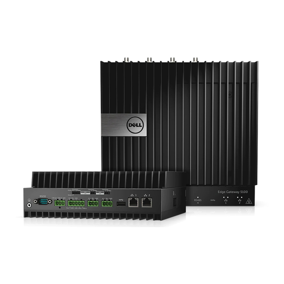
The Dell Edge Gateway 5000/5100 series allows you to connect (wired or wireless) to network enabled devices and manage them remotely in your existing network ecosystem. The system can be either mounted on the wall using the Dell approved wall mount kit or mounted into your existing rack infrastructure using the DIN-rail mounting bracket. -
Page 7: System Views
System views System—Front Features Power button Press and hold for 2 seconds to turn on the system if it is turned off. NOTE: For more details about the LED indicators on the front of the system, see indicators. -
Page 8: System-Front (Led Indicators)
System—Front (LED indicators) Features Power status LED Indicates the power‑state of the system. Mobile broadband status LED Indicates the mobile broadband status and network activity. Wireless status LED Indicates the wireless connectivity status and network activity. Bluetooth status LED Indicates the Bluetooth status and activity. Cloud connection status LED Indicates the cloud connection status. -
Page 9: Serial Port (Rs232) Connector Mapping
Features RS485 port Connect a RS485 device. RS485 port Connect a RS485 device. USB 3.0 port Connect a USB 3.0 device. Network port Connect an Ethernet (RJ45) cable from a router or a broadband modem for network or internet access. Network port Connect an Ethernet (RJ45) cable from a router or a broadband modem for network or internet access. -
Page 10: Rs422/485 Connector Mapping
Signal A(-) B(+) RS422/485 connector mapping Signal TXA(-) / A(-) TXB(+) / B(+) RXA(-) RXB(+) System—Bottom (DIP switches) Feature RS422/RS485 port toggle switch Toggle between RS422 or RS485 standard. RS422/RS485 port resistor switch Enable/disable the differential termination resistor. RS422/RS485 port bias resistor switch Enable/disable the bias resistor for the RS422/RS485 port. -
Page 11: System-Top
System—Top Features Mobile broadband antenna port (port one) Connect an antenna to increase the range and strength of the mobile broadband signals. Micro-SIM card slot Insert a micro-SIM card to connect to a mobile broadband network. Mobile broadband antenna port (port two) Connect an antenna to increase the range and strength of the mobile broadband signals. -
Page 12: Hdmi Connector Mapping
HDMI connector mapping Signal TMDS Data2+ TMDS Data2 Shield TMDS Data2− TMDS Data1+ TMDS Data1 Shield TMDS Data1− TMDS Data0+ TMDS Data0 Shield TMDS Data0− TMDS Clock+ TMDS Clock Shield TMDS Clock− Reserved Ground +5 V (min. 0.055 A) Hot Plug Detect... -
Page 13: System-Left
System—Left Features Power module expansion port Connect an external power module for increased power options. 24 V AC/DC power Phoenix connector Connect an 24 V AC/DC power connector to provide power to your system. 19.5 V DC power adapter port Connect a 19.5 V DC power adapter connector to provide power to your system. -
Page 14: 24 V Ac/Dc Power Port
24 V AC/DC power port 19.5 V DC power adapter port... -
Page 15: System-Right
System—Right Features IO expansion port Connect an external expansion module for additional IO ports. -
Page 16: Setting Up Your Dell Edge Gateway
Electrical Codes and Regulations. WARNING: To ensure the protection provided by Dell Edge Gateway is not impaired, do not use or install the system in any manner other than that which is specified in this manual. -
Page 17: Instructions D'installation Professionnelles
External antenna Use only the antenna(s) which have been approved by the applicant. Non-approved antenna(s) may produce unwanted spurious or excessive RF transmitting power which may lead to a violation of FCC/IC limits and is prohibited. Installation procedure Please refer to user’s manual for the detail. WARNING: Please carefully select the installation position and make sure that the final output power does not exceed the limits set forth in relevant rules. -
Page 18: Industry Canada Statement
• This transmitter must not be co-located or operating in conjunction with any other antenna or transmitter. Radiation Exposure Statement: This equipment complies with FCC radiation exposure limits set forth for an uncontrolled environment. This equipment should be installed and operated with minimum distance 20cm between the radiator & your body. NOTE: The country code selection is for non-US model only and is not available to all US model. -
Page 19: Setting Up The Edge Gateway
The maximum antenna gain permitted for devices in the band 5725-5825 MHz shall comply with the eirp limits specified for point-to-point and non point-to-point operation as appropriate. The worst-case tilt angle(s) necessary to remain compliant with the eirp elevation mask requirement set forth in Section 6.2.2(3) shall be clearly indicated. - Page 20 Install the WWAN antenna to enable the wireless connections—optional. Connect a display to the Edge Gateway (if necessary).
- Page 21 Connect a keyboard and mouse if accessing the Edge Gateway directly. Connect a grounding cable to the Gateway (if necessary). Connect a SELV/limited energy circuit power source to the Edge Gateway and press the power button to turn it on. 24 V AC/DC 19.5 V DC...
-
Page 22: Mounting The Edge Gateway On The Wall
If setting up the Edge Gateway for the first time, complete the operating system setup. NOTE: The Edge Gateway is shipped with either Windows 10 Enterprise, Ubuntu Snappy, or Wind River Linux operating systems. Do this later when prompted to enter the product key. NOTE: On Windows 10 OS, select ubuntu . - Page 23 Drill four holes in the wall that correspond to the holes in the mounting bracket, then place the Edge Gateway against the wall and align the holes in the mounting brackets with the holes in the wall. Tighten the screws to secure the Edge Gateway to the wall.
-
Page 24: Mounting The Edge Gateway On A Din Rail
Mounting the Edge Gateway on a DIN rail The Edge Gateway can be mounted on a DIN rail. The DIN rail bracket mounts to the back of the Edge Gateway. Align the screw holes on the DIN rail mount to the back of the Edge Gateway, place the screws on the DIN rail mount and secure it to the Edge Gateway. - Page 25 Mount the Edge Gateway on a DIN rail. Secure the Edge Gateway to the DIN rail by pressing the latch.
-
Page 26: Inserting A Micro-Sim Card And Activating Your Mobile Broadband
Inserting a micro-SIM card and activating your mobile broadband CAUTION: Dell recommends that you insert the micro-SIM card before powering on the Edge Gateway. Shut down your Edge Gateway. Locate the micro-SIM card slot. Use a paper clip or SIM eject tool to eject the micro-SIM card tray. - Page 27 Click the play button to connect to your HSPA+ network. NOTE: Click the information button to view the International Mobile Equipment Identity (IMEI) and Integrated Circuit Card Identifier (ICCID) information. Click the stop to disconnect from your HSPA+ network. If the Edge Gateway is shipped with LTE Verizon (DW5812) WWAN or LTE AT&T (DW5813) card: Select the network icon from the taskbar and then click Cellular.
- Page 28 Example: at+cgdcont=3,"IPV4V6","vzwinternet". NOTE: If the command runs successfully, the message OK appears. Configure the Network Control Mode with the at#ncm command. Example: at#ncm=1,3. Activate the Packet Data Protocol with the at+cgact command. Example: at+cgact=1,3. To view the PDP Context Read Dynamic Parameters, that is, bearer_id, apn, ip_addr, subnet_mask, gw_addr, DNS_prim_addr, DNS_sec_addr, P-CSCF_prim_addr, and P-CSCF_sec_addr parameters, run the at+cgcontrdp command.
- Page 29 Example: at+cgdcont=3,"IPV4V6","broadband". NOTE: If the command runs successfully, the message OK appears. Configure the Network Control Mode with the at#ncm command. Example: at#ncm=1,3. Activate the Packet Data Protocol with the at+cgact command. Example: at+cgact=1,3. To view the PDP Context Read Dynamic Parameters, that is, bearer_id, apn, ip_addr, subnet_mask, gw_addr, DNS_prim_addr, DNS_sec_addr, P-CSCF_prim_addr, and P-CSCF_sec_addr parameters, run the at+cgcontrdp command.
-
Page 30: Setting Up Your Operating System
Select Fully clean the drive. Select Reset. Windows 10 IOT Enterprise LTSB 2015 basic functions BIOS Update BIOS updates for the Edge Gateway may be downloaded from https://www.dell.com/support. The download will include an executable that may be ran from the local machine. -
Page 31: Common Port Mappings
Watchdog Timer The Watchdog Timer for Windows 10 IoT Enterprise LTSB 2015 is controlled via the BIOS setting. Enter the BIOS during boot by pressing F2. The Watchdog Timer is enabled and disabled under the BIOS setting Watchdog Timer. TPM Support Windows 10 IoT Enterprise LTSB 2015 supports TPM 2.0. -
Page 32: Snappy Ubuntu Core 15 And 16
Edge Gateway I/O Module GPIO Mapping The GPIOs on the external I/O Module for the Edge Gateway are behind PIC microcontroller. The PIC microcontroller is exposed to the host system and to the host OS as a USB-HID device. Software applications developed to communicate with the GPIOs may use the protocol defined in the following set of references to communicate with the GPIO modules. -
Page 33: Restoring Ubuntu Snappy
Connect a keyboard, mouse, and monitor to the Edge Gateway, or connect to the Edge Gateway through a KVM session. Turn on the system. Press F12 when the Dell logo is displayed on the screen to enter the boot menu. Select Factory Restore from the boot menu. -
Page 34: Ubuntu Core Os Basic Function
returns Linux ubuntu.localdomain 3.19.0-47-generic #53-Ubuntu SMP Mon Jan 18 14:02:48 UTC 2016 x86_64 x86_64 x86_64 GNU/Linux Running command, (plano)ubuntu@localhost:~$ sudo snappy info returns Linux power5000.localdomain 3.19.0-47-generic #53-Ubuntu SMP Mon Jan 18 14:02:48 UTC 2016 x86_64 x86_64 x86_64 GNU/Linux Running command, (plano)ubuntu@localhost:~$ snappy list -v returns Name... -
Page 35: Uefi Capsule Update
Action Ubuntu Core 15 Ubuntu Core 16 remove cloud- init $sudo mount –o remount,rw / Adjust grub configuration $sudo vi /boot/grub/grub.cfg Remount Ubuntu Snappy 16 root file Snappy 16 rootfs is Read-Only system as read/write UEFI capsule update NOTE: For more information about fwupd commands, see http://www.fwupd.org/users. This fwupgmgr tool/commands are used to update UEFI BIOS firmware on the system. -
Page 36: Serial Port
#echo 0 > /sys/class/gpio/gpio346/value Serial Port Serial device nodes mapping. Table 2. Serial device nodes mapping table. Port Type Connector Device Node RS232 /dev/ttyS6 RS422_485 5 pin terminal /dev/ttyS4 RS485 3 pin terminal /dev/ttyS5 RS485 3 pin terminal /dev/ttyS2 Execute the #sudo chmod 777 /dev/ttyS# command on two systems, where # is port number corresponding to ports being used. -
Page 37: Network Manager - Ubuntu Core 15
Network Manager – Ubuntu Core 15 Network-Manager is a native Ubuntu Snappy Connection Manger, the application handles multiple network devices, provides detection and configuration for system to automatically connect to network. A command line utility nmcli is included with Network-Manager to support non-graphical user interface. WWAN (nmcli example) •... -
Page 38: Network Manager - Ubuntu Core 16
Run the $quit command to quit the bluetoothctl console. Network Manager – Ubuntu Core 16 Network-Manager is a native Ubuntu Snappy Connection Manger, the application handles multiple network devices, provides detection and configuration for system to automatically connect to network. A command line utility nmcli is included with Network-Manager to support non-graphical user interface. -
Page 39: Flashing A New Os Image
USB 2.0 or USB 3.0 flash drive (4GB min.) • Ubuntu 15.04 ISO. NOTE: You can download the latest version of the Ubuntu ISO file from http://releases.ubuntu.com. • A released Ubuntu Core 15.04 image from Dell/Canonical: <unique name>.img.xz • Dell Edge Gateway 5000 series hardware • LCD monitor •... -
Page 40: Flashing The Bios
Insert the USB flash drive in one of the available USB ports on the Edge Gateway. Power on the Edge Gateway. Press F12 when the Dell logo is displayed on the screen to enter the One-time boot screen. On the One-time boot screen, choose Flash the BIOS . -
Page 41: Restoring Wind River Linux
The Wind River Linux operating system is damaged. Connect a keyboard, mouse, and monitor to the Edge Gateway, or connect to the Edge Gateway through a KVM session, Dell Wyse Cloud Client Manager (CCM), or Dell Command | Monitor (DCM). -
Page 42: Wind River Linux Basic Functions
Wind River Linux Basic Functions Preinstalled Packages Run the root@WR-IDP-xxxx:~# rpm -qa command to list all the packages installed on the Wind River Linux OS. NOTE: If you are looking for a specific package, you have to pipe the output of the root@WR-IDP-xxxx:~# rpm -qa command to search for that specific package. - Page 43 TPM support (HW TPM module dependency) Run the root@WR-IDP-xxxx:~# tpm_statistic command displays the status of TPM service. If the TPM is functional and enabled in the BIOS, below would be the expected results, when tpm_statistic command is executed. Expected result: The expected result is for TPM Chip Presence: Normal. Example of the response to the above command should be similar to the output shown below.
- Page 44 • • wlan0 Network configuration and default setup The following commands can be used to configure different network interfaces on the system with Wind River Linux on it. Network configuration on Wind River Linux IDP 3.1 environment can be performed through the LuCi web interface. NOTE: The LuCi web interface supported in the default OS image.
- Page 45 through the system. The issued IP addresses by the access point and eth1 interface are in the 192.168.1.x subnet. The default access point SSID for the access point is IDPDK-5591. The bridge configuration can be modified using LuCi web interface. Follow Intel/Wind River’s documentation for more details on configuring, WAN, WLAN, and br-LAN network interfaces using LuCi web interface.
- Page 46 Launch minicom terminal utility on the system with one of the USB ACM device port to identify that we have the correct USB ACM device for Telit LE910 device before configuring the device, e.g. below shows how to launch minicom with ttyACM1 as interface: •...
- Page 47 Description: The following are a capture from a sample session that was performed on a Dell Edge Gateway platform with default Wind River Linux OS image to establish LTE connectivity using Verizon LE910 module and Verizon SIM card. The commands highlighted were typed and the other is response from the system.
- Page 48 Description: The following method can be used to disable or delete the WWAN connection that was setup using the descriptions mentioned in the previous sections. Launch minicom as defined in the other sections and choose the appropriate ttyACM port for the Telit module Inside the minicom terminal send the following AT commands At+gmi (to make sure it is the Telit module)
- Page 49 Register Edge Gateway at Intel Developer Hub The Dell Edge Gateway 5000 series with Wind River Linux IDP 3.1 supports Developer Hub portal within the Gateway. This portal can be used for performing variety of configuration functions on the Gateway along with using it for developing software layers on top of the base Wind River Linux OS Image, sensor devices integration to the gateway and hardening of the combined application / base OS image for deployment.
- Page 50 IDP 3.1 base OS image. The Dell Edge Gateway 5000 product with Wind River Linux IDP 3.1 base image from the factory is shipped with particular version of the RCPL package(RCPL 13) from Wind River. The RCPL versions from Wind River are periodically updated by the Wind River team and it is recommended for the Edge Gateway user/customers to upgrade to the latest version of RCPL by following the procedure/ steps indicated below before developing software stack and middleware on top of the OS image.
- Page 51 Intel / Wind River describing the procedure and process to obtain the Windshare repository credential from Intel/Wind River. – If you have not gotten such email, contact your sales contact at Dell to get you through the registration process to obtain credentials for the Windshare repository.
- Page 52 • Once the update of the OS is complete, the Gateway should reboot and now the system should be upgraded to the latest RCPL release available for the Gateway 5000 product at the Windshare repository. At this point the user should have an environment ready to develop other layers of applications on top of the Gateway 5000 system.
- Page 53 Serial Port Mapping Description: The following table show the serial port mapping on the Edge Gateway 5000 platform installed with Dell factory installed Wind River Linux OS image. For dip switch setting on the Edge Gateway for RS422 and RS485 ports please refer to appropriate hardware installation guide document.
- Page 54 The I/O module GPIO mapping and references will be provided as a separate technical sheet and article and will be released at the support web portal for user/customer reference. Edge Gateway I/O Module PCIe expansion mapping Description: The PCIe slot on the external I/O module for the Edge Gateway are driven directly from the host PCIe bus. Since it is generic PCIe expansion there are no PCIe device specific drivers integrated into the Wind River Linux OS image.
- Page 55 Edge Gateway CAN Module Functions Description: The Edge Gateway supports an optional CAN module that is mounted inside the Gateway itself. The CAN module is enumerated to the OS as a USB device as USB HID device to the Linux kernel driver layer on the Wind River Linux host. There are no native application software on the factory installed OS image to perform CAN protocol for this device.
-
Page 56: System Specifications
5100 Standard FR4 Isola 370HR Intel E3B25/E3827 Intel E3B25/E3827 Memory Dell-managed Dell-managed BIOS Flash Dell-managed 128 MB SPI FLASH Dell-managed 128 MB SPI FLASH Super I/O Fintek F81960D-I Fintek F81960D-I LAN on system-board Realtek RTL81191-CG Realtek RTL81191-CG Nuvoton NPCT6SO series... -
Page 57: Memory
Memory 5000 5100 Type DDR3L DDR3L Memory channel Single/dual Single/dual Minimum memory 2 GB 2 GB Maximum system memory 8 GB 4 GB Drives and removable storage 5000/5100 Supported number of mSATA hard drives (maximum) 32GB M.2 Solid State Drive 64GB M.2 Solid State Drive NOTE: For hard drives, ‘GB’... - Page 58 Mechanical and environmental specifications Mounting Wall mounted Connector type SMA male Antenna color White Cable type Plenum rated low loss RG58 Cable color White Mounting bracket Swivel type (plastic) Mounting bracket length (approximate) 175 mm (6.89 in) Mounting bracket color Black Pig tail length 500 mm ±...
-
Page 59: Communications-Wwan Antenna
Coaxial cable specification Jacket pullout 4.5 pound-force minimum on 76.2 mm (3 in) section at 12.7 mm (0.5 in) per minute Minimum bend radius 12.7 mm (0.5 in) static bend Leakage -90 dB Communications—WWAN antenna General specifications Antenna PCB Dipole type Number of ports... - Page 60 Mechanical and environmental specifications Mounting bracket Swivel type (plastic) Mounting bracket length (approximate) 175 mm (6.89 in) Mounting bracket color Black Pig tail length 1000 mm (39.37 in) Coaxial cable specification Impedance 50 ± 2.0 ohms Structural return loss -16 dB or better from 100-2500 MHZ un-terminated sample (direct bridge method) Nominal RTL reference -16 dB or better to 6.0 GHz...
- Page 61 Measured antenna peak gain (antenna only) Main antenna Auxiliary antenna Frequency (MHz) Horizontal (dBi) Vertical (dBi) Horizontal (dBi) Vertical (dBi) 0.09 0.63 1.19 1.12 -0.11 0.66 0.89 0.91 -0.27 0.60 0.51 0.78 -0.08 0.55 0.42 0.86 0.17 0.57 0.68 0.97 0.35 0.60 0.86...
- Page 62 Measured antenna peak gain (antenna only) 1.71 1.00 2.13 0.94 1.65 1.03 1.87 0.82 1.57 1.16 1.61 0.74 1.30 1.36 1.24 0.60 1.43 1.31 0.98 0.69 1710 2.19 2.18 1.83 2.39 1730 2.25 2.29 1.66 2.36 1750 1.90 2.15 1.39 2.29 1770 1.33...
-
Page 63: Graphics/Video Controller
Measured antenna peak gain (antenna only) 2400 1.29 1.91 1.85 1.63 2500 3.17 2.75 2.94 2.47 2515 3.11 2.62 2.78 2.47 2535 2.88 2.42 2.55 2.48 2555 2.51 2.09 2.18 2.46 2570 2.21 1.91 1.92 2.46 2570 2.21 1.91 1.92 2.46 2595 1.89... -
Page 64: Dimensions And Weight
5000/5100 Universal audio jack None USB 2.0 USB 3.0 CANBus (3–pin Phoenix connector) Dimensions and weight NOTE: System weight and shipping weight are based on a typical configuration and may vary depending on PC configuration. A typical configuration includes: integrated graphics, one hard drive, and one optical drive. Product dimensions and weight 5000 5100... -
Page 65: Environmental And Operating Conditions
5000 5100 IO module Power module IP65 rugged enclosure Depth 72.7 mm (2.86 in) 83 mm (3.27 in) 56.2 mm (2.21 in) 72.7 mm (2.86 in) 91.8 mm (3.61 in) Environmental and operating conditions Environmental conditions—System Ingress protection rating IP50 Temperature range: Edge Gateway 5000 Operating (with a maximum temperature gradation of... - Page 66 Environmental requirements NOTE: Enclosure meets IP50 with the pre-installed PCIe blank bracket. System IP rating depends on the PCIe card IP rating. Temperature range: Operating (with a maximum temperature gradation of -30°C to 70°C (-22°F to 158°F) 15°C per hour) NOTE: The maximum operating temperature is derated 1°C/305 m(1000 ft) above sea level altitude.
-
Page 67: Environmental Conditions - Power Module
System ambient after altitude Maximum supported power Maximum supported power Maximum supported power derating (°C) dissipation (W) for 85°C or dissipation (W) for 70°C still dissipation (W) for 55°C still above still air rated PCIe air rated PCIe cards air rated PCIe cards cards Not supported Not supported... -
Page 68: Environmental Conditions - Enclosure
Environmental requirements NOTE: The maximum operating temperature is derated 1°C/305m (1000ft) above sea level altitude. Storage -15.20 m to 10,668 m (-50 ft to 35,000 ft) Environmental conditions - Enclosure IP65 Ingress protection rating NOTE: Require IP65 or above conduit connection. Temperature range: •... -
Page 69: Power
Maximum altitude 5000 5100 Operational -15.20 m to 5000 m (-50 ft to 16,404 ft) -15.20 m to 5000 m (-50 ft to 16,404 ft) Non-operational –15.2 to 10,668 m (–50 to 35,000 ft) –15.2 to 10,668 m (–50 to 35,000 ft) Power Power adaptor (optional) General parameters... -
Page 70: Security
(for Edge Gateway 5000) PANASONIC BR2032 Lithium (for Edge Gateway 5100) NOTE: Dell recommends checking or replacing the coin-cell battery prior to operation if the system has been disconnected from a power source for more than two years. Security 5000/5100 •... - Page 71 Available on-site service NOTE: For a copy of our guarantees or limited warranties, write to ‘Dell USA L.P., Attn: Warranties, One Dell Way, Round Rock, TX 78682’. For more information, visit www.dell.com/warranty. NOTE: Service may be provided by third-party. A technician will be dispatched if necessary following phone-based troubleshooting.
-
Page 72: O Module Overview
The I/O module allows you to install a PCIe x1 card and adds additional ports to your Dell Edge Gateway. NOTE: The power module is required to be installed with the Dell Edge Gateway to enable and use the I/O expansion module. -
Page 73: Io Module-Top
IO module—Top Features Top release latch Push both the top and bottom release latches to disconnect the power module from the Edge Gateway. USB 2.0 port For USB 2.0 devices. USB 2.0 port For USB 2.0 devices. GPIO port Connect a GPIO 8–pin cable. RS232 port Connect an RS232 cable. -
Page 74: Io Module-Bottom
RS232 port on IO expansion module connector mapping Signal Signal IO module—Bottom Features Bottom release latch Push both the top and bottom release latches to disconnect the power module from the Edge Gateway. PCIe x1 card slot Install PCIe x1 card on the IO module. IO module cover removal screw Remove the screw to open the box and install the PCIe card. - Page 75 Align the power module guide pins to the power module port on the Edge Gateway and slide the power module toward the Edge Gateway until fully seated. Ensure the top and bottom latches are locked to secure the module to the Edge Gateway.
- Page 76 Install the Edge Gateway and the IO module along with the power module at a desired location using a wall-mount bracket or the DIN rail mount. Wall mount bracket DIN rail mount Connect to a power source, and press the power button.
-
Page 77: Installing The Pcie Card Into The Io Module
NOTE: Connect a power cable to the 24 V AC/DC or 19.5 V DC power adapter port on the power module. NOTE: The power adapter and sealed lead-acid battery is sold separately. NOTE: To enable and use the IO expansion module, you must also install the power module. Installing the PCIe card into the IO module CAUTION: Electrical and electronic devices are sensitive to electrostatic discharge (ESD). - Page 78 Remove the PCIe expansion card-slot cover. Install the PCIe card into the PCIe expansion card slot on the IO expansion module and secure with a screw. Replace the cover on the IO expansion module.
- Page 79 Tighten the screw that secures the cover to the IO expansion module. NOTE: Replace the dust caps on any unused ports and connectors.
-
Page 80: Power Module Overview
Power Module Overview The power module allows you to connect additional power sources to your Dell Edge Gateway. The power module allows you to connect to all three power sources, that is, the 24V AC/DC, 19.5 VDC, and a battery. -
Page 81: Power Module-Front
Power module—Front Features Power status LED Indicates the power‑state of the power module and the Edge Gateway. Battery status LED Indicates the power‑state of the attached battery. -
Page 82: Power Module-Bottom
Power module—Bottom Features 19.5 V DC power adapter port Connect a 19.5 V DC power adapter to provide power to your Edge Gateway. 24 V AC/DC power port Connect a 24 V AC/DC power source to power your Edge Gateway. Sealed lead-acid battery port Connect an external battery to the power module to provide back-up power in case of power interruption. - Page 83 24 V AC/DC power port Sealed lead-acid battery port...
-
Page 84: Power Module-Top
Power module—Top Features Top release latch Push both the top and bottom release latches to disconnect the power module from the Edge Gateway. -
Page 85: Power Module-Right
Power module—Right Features Edge Gateway expansion port Connect the power module to the Edge Gateway for increased power options and to power the IO expansion module. Setting up the power module WARNING: Before installing the power module, shut down the Edge Gateway and disconnect the power cable. NOTE: To enable and use the IO expansion module, you must also install the power module. - Page 86 Align the power module guide pins to the power module port on the Edge Gateway and slide the power module until fully seated. Ensure the top and bottom latches are locked to secure the module to the Edge Gateway. Secure the power module to the wall or to the DIN rail.
- Page 87 Wall mount bracket DIN rail Connect the power sources and press the power button on the Edge Gateway.
-
Page 88: Specifications - Power Module
NOTE: You can connect the power cable to the 24V AC/DC, 19 VDC, and a battery simultaneously. NOTE: The power adapter and sealed lead-acid battery are sold separately. NOTE: Installing the battery is optional. Dell recommends that you connect a sealed 12V lead-acid battery to the power module. - Page 89 Environmental requirements NOTE: The maximum operating temperature is derated 1°C/305m(1000ft) above sea level altitude. Non-operating -40°C to 70 °C (-40°F to 158°F) Relative humidity (maximum): Operating (with maximum humidity gradation of 10% 10% to 90% (non-condensing) per hour) Non-operating ((with maximum humidity gradation of 5% to 95% (non-condensing) 10% per hour) Altitude (maximum, unpressurized):...
-
Page 90: Enclosure Overview
Enclosure Overview The rugged enclosure allows you to install the Dell Edge Gateway in harsh environment’s, like locations that are subjected to high temperature variation, dust particle, and humidity. Enclosure (optional) view Enclosure - Side Features Rugged enclosure Install the Edge Gateway in the rugged enclosure when using in harsh environments condition. -
Page 91: Setting Up The Enclosure
Features Cable tie-off (17) To prevent accidental cable disconnection, tie all cables to the cable tie-off guides. Cable conduit openings (8) Route the cables through the conduits (1 inch and 0.75 inch diameter). Primary ground (internal) Connect the grounding cable to the system. Primary ground (external) Connect the grounding cable to the system. - Page 92 Secure the enclosure to the wall bracket by using the rubber washers and screws. Secure the enclosure mounting brackets to the Edge Gateway by using the screws. NOTE: Before attaching the brackets to the Edge Gateway, note the correct orientation of the brackets. Position the Edge Gateway onto the enclosure’s two locator pins, and then place and tighten the screws to secure the Edge Gateway to the enclosure.
- Page 93 Connect the intrusion switch to the system. Remove the desired conduit plugs on the bottom or the left side of the enclosure and install the wiring conduits. NOTE: To ensure that dust and water does not enter the enclosure, install a conduit rated as IP65.
- Page 94 Route the cables through the conduits and connect the cables to the desired connectors. NOTE: To reduce the risk of accidental cable disconnection, tie all cables to the cable tie-off guides. 10. Close and securely latch the enclosure door.
-
Page 96: Setting Up The Zigbee Dongle
Setting up the ZigBee dongle CAUTION: Do not connect the ZigBee dongle if the Edge Gateway is installed inside the enclosure. NOTE: Do not connect the ZigBee dongle to the internal USB port of the IO expansion module. Shut down your Edge Gateway. Connect the ZigBee dongle to any external USB port on your Edge Gateway. -
Page 97: Bios Defaults
BIOS defaults System configuration 5000 5100 Integrated NIC Enable w/PXE Enable w/PXE Serial port Disable Disable SATA operation AHCI AHCI Drives Enable (SSD-1) Enable (SSD-1) SMART reporting Disable Disable USB configuration Enable (boot support, front USB ports, Enable (boot support, front USB ports, rear USB ports) rear USB ports) Performance... -
Page 98: Power Management
5000 5100 Password bypass Disable Disable Password changes Enable Enable TPM security Enabled Enabled Computrace® Deactivate Deactivate Chassis intrusion On (Silent) On (Silent) CPU XD support Enable Enable Admin setup lockout Disable Disable OROM keyboard access Enable Enable HDD protection support Disable Disable Power management... -
Page 99: Post Behavior
POST behavior 5000 5100 Numlock LED Enable Enable Keyboard errors Enable Enable Adaptor warning Enable Cloud desktop 5000 5100 Server lookup method Server name CDServer CDServer Server IP address 255.255.255.255 255.255.255.255 Server port 06910 06910 Client address method DHCP DHCP Client IP address 255.255.255.255 255.255.255.255... -
Page 100: Other Documents You May Need
Dell Edge Device Manager Getting Started Guide • Dell SupportAssist For Dell OpenManage Essentials Quick Start Guide • Dell Command | Monitor User's Guide Additionally, for more information on using Dell Data Protection | Encryption see the documentation for the software at https:// www.dell.com/support/manuals. -
Page 101: Contacting Dell
Go to www.dell.com/contactdell. Verify your country or region in the drop-down list at the bottom of the page. Select the appropriate service or support link based on your requirement or choose the method of contacting Dell that is convenient for you.
Need help?
Do you have a question about the Edge 5000 Series and is the answer not in the manual?
Questions and answers